01
03
16
week 12 | moulding and casting
17
Oh yeah! Moulding and casting! The assignment we had to do was to make a 3D mould and cast parts from it.
Oh yes - uhm - there is a real problem. Our Lab does not own a usable CNC mill and there was not enough time to travel to our Friends at Kamp-Lintfort to use their mill, so we had to improvise a bit. Or a bit more...
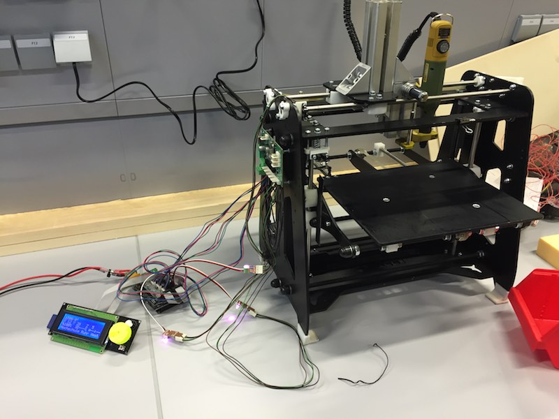
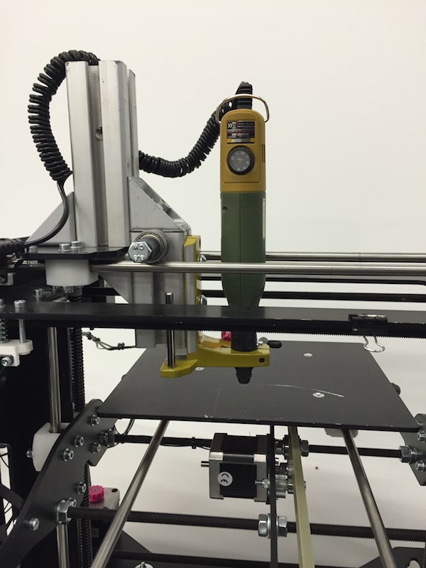
The last months, I used a very reliable 3D printer, called Orca from Mendel-Parts in the Netherlands, for a research project - after some sketches, thinking and some Club-Mate this machine was the choosen one. Normally we use this machine as 3d printer - but for this research project, I added a multi purpose interface out of Item aluminium profiles, which gave us the ability to add any machine head. This modification reduces the machining area to only 50%, but you are able to machine everything you want with every head you want. The printer is driven by a normal RAMPS 1.4 board for 3D printer. (oh, yes - it is a real prototyping machine - no cases etc.)
18
As CAM processor, we used the online - and - offline version of FabModules. As the online FabModules version crashed when reading one of our .stl files, we started to use the offline version - but this one made some faults and problems either.
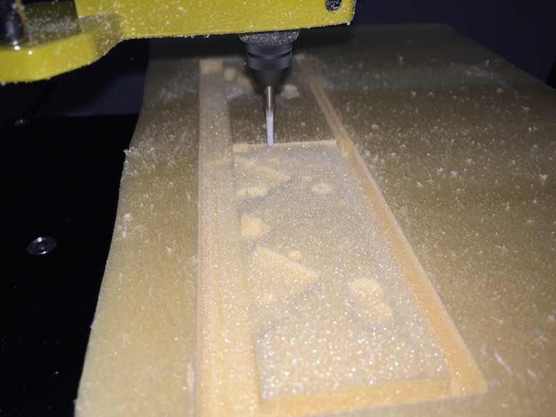
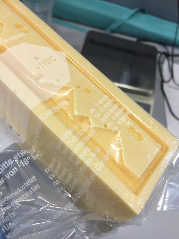
After some testing around, I made a 3D model of the first Super Mario Land level, this was necessary to get a projected height map from the side in FabModules as PNG. This heightmap needed some adjustments to comply with my requirements. After this step, we started milling foam with a very nice result for a machine and especially a firmware, which is not made for this job (it is a modified Marlin version). The only problem left at this point: the Z-axis had some strange behavior we have to fix asap. It looses steps - but only while using the through FabModules generated G-Code.
19
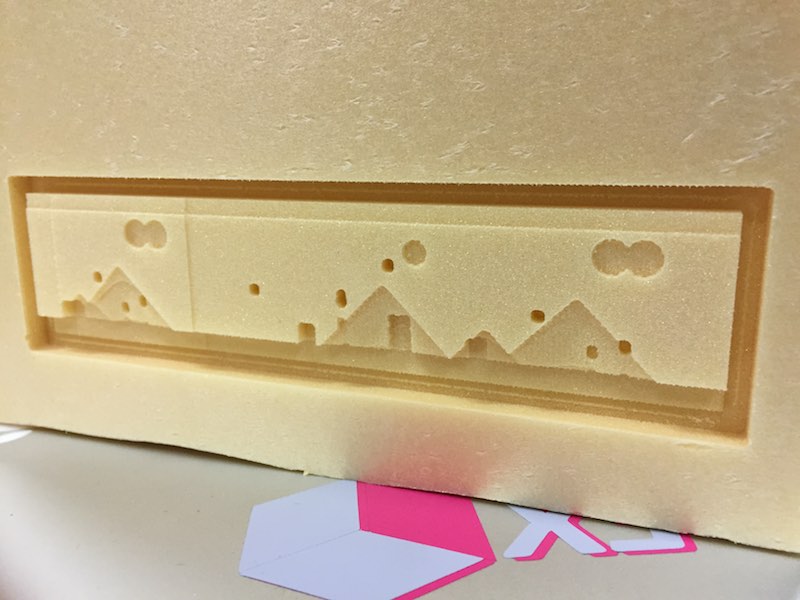
After this step, I had to cast the parts I wanted to have... - the SuperMario Land ice cube tray! To gain the best casting quality, I used a vacuum pump and a plastic bag, to suck the silicone into my mould. This is my first test...
For my mould, I bought FDA approved silicone from Amazon. This is a two component silicone with a 1:1 mixture.
20
After kneading the mixture, I filled the silicone into the mould and used the vacuum pump.
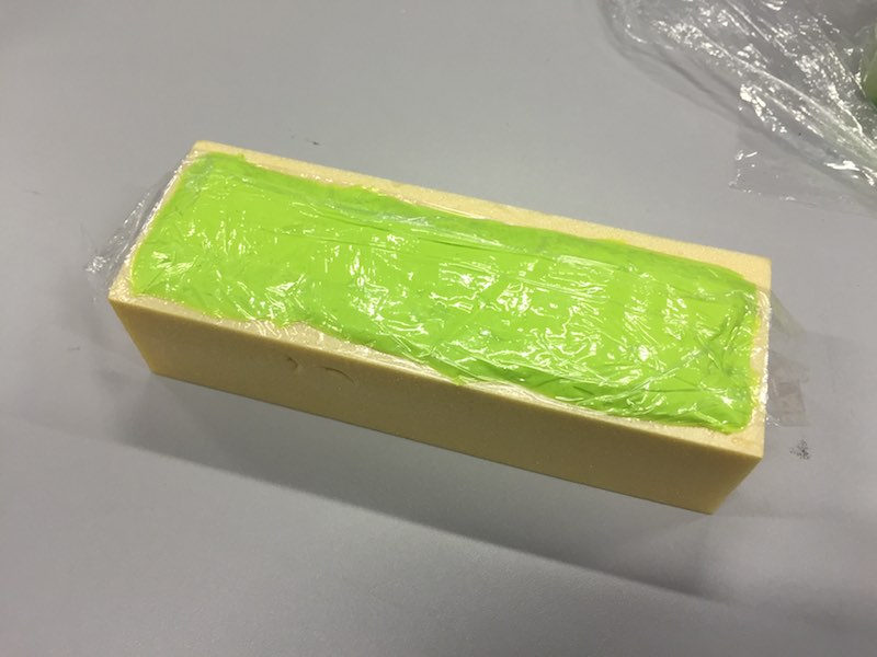
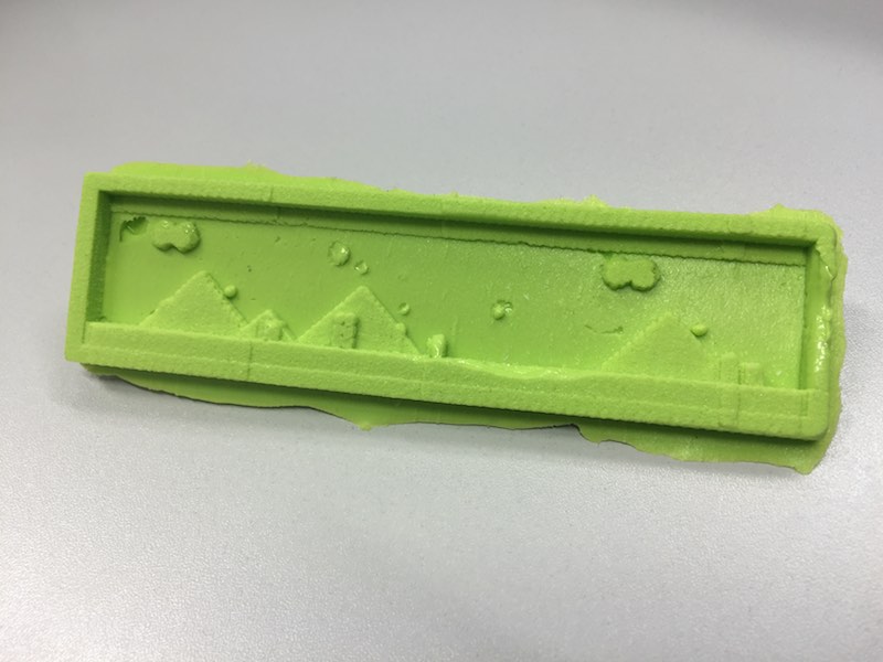
The finished ice cube tray:
21
Download my Super Mario Land Level 1 as Inventor model
Download my Super Mario Land Level 1 as STL model
22
Ok ok ... this was my first try, back in the year 2016.
Let's do a bit more exciting stuff...
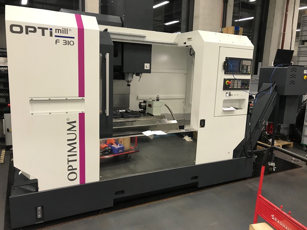
As the FabLab still does not have a CNC-Mill, my new job in the Technical Center for Thermal and Mechanical Process Engineering offers me the opportunity to use our new and not that small CNC-Mill. It's an Optimum F310 4-axis.
The CNC-Mill is equipped with an 1200x520 mm milling table and a 4th axis, which rotates around X, as A axis. We use this mill to produce machine parts and screw-conveyor, normally.
23
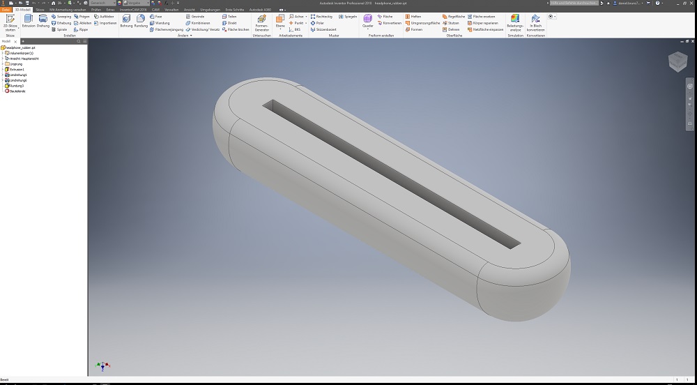
I thought a lot of time about the moulding & casting assignment. I had no idea what to cast, until I saw the wildcard week and the chance to use a complete different process. The part I casted, is a protection for my headphone on my - in the wildcard week made - headphone stand.
The first step was to create the part, then I had to design both sides of the mould. The casted part is a really simple part, which will be casted out of food-safe silicone.
This is the other side of the mould, where the headphone will lay on. The cone is the other half of the downsprue.
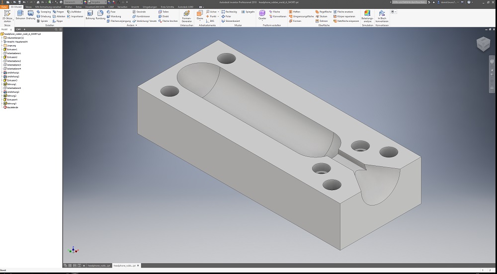
To avoid the part from sliding from the headphone stand, I had to design a deep groove, where it will be mounted. This groove is too deep to be in one side of the mould. The result: I had to design a double-sided mould with a bar across both moulds. The design was not really tricky but the CAM resulted in some headaches. The holes are for aligning and screwing both sides of the mould together. This is the first side of the mould.
24
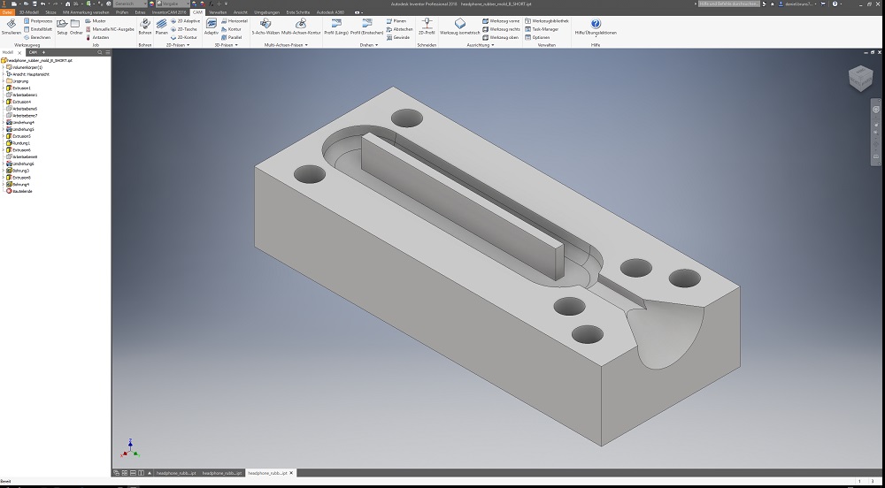
The next step was to prepare the files for milling. I'm using HSM Ultimate at the moment. This is a very neat and easy tool. It does not offer the most functions, but is easy to learn for our students. We're changing to InventorCAM this year, but the postprocessor was not finished when I milled my parts.
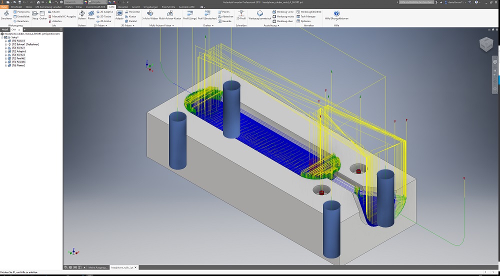
This side - the a side - was not really tricky to set up in the CAM program. As I only got a 25x25mm aluminium square rod, I had to rough a lot of material down. For this facing step, I used a large 80mm 45° face-mill from Hoffmann. The second step was drilling the holes with a 8mm drill. As the machine does this a lot better than everybody could do, I used this option to get perfect holes. The downsprue and the negative were roughed with a 6 mm roughing endmill before the finish run with a 6mm radius cutter .
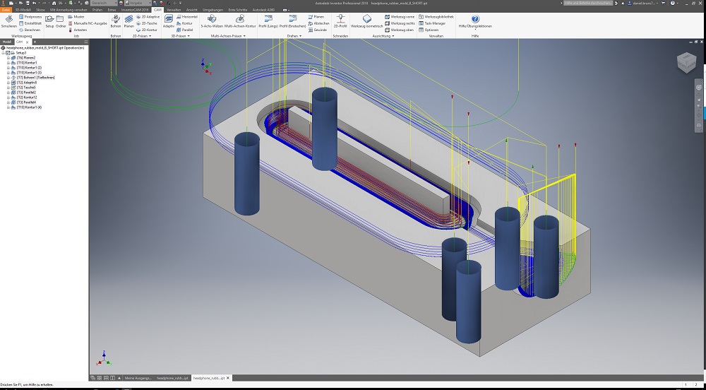
The b-side of the mould was a lot more difficult to set up. I had to mill upon I reached the bar, which is only 3 mm thick but 10 mm high. The remaining material on the interface side was milled down with a 90° face-mill from Hoffmann. This allows to gain a very smooth surface and an exact 90° angle on the middle bar. The holes, downsprue and the negative were milled/roughed/finished with the same tools like the a-side. The only trap door was the bar, where I had to be very careful.
25
Milling
The milling process ran without any problems. I made some pictures of this process.
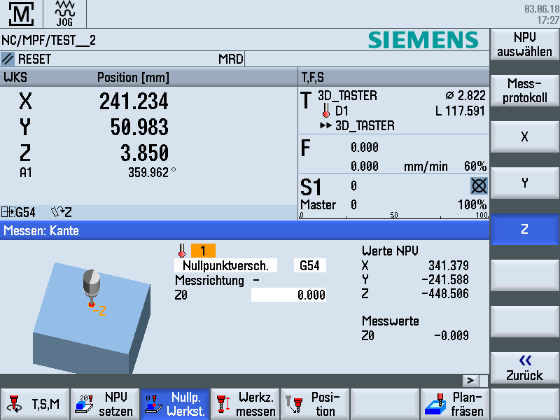
First of all, I had to set the zero point offset. The mill is equipped with a nice work piece and tool measurement system, called TC52 and ZX-Speed IR from Blum. This system allows to measure the workpiece and the tools automatically and calculate the right coordinates. First step: set the Z-axis workpiece zero point in the Siemens 828D control.
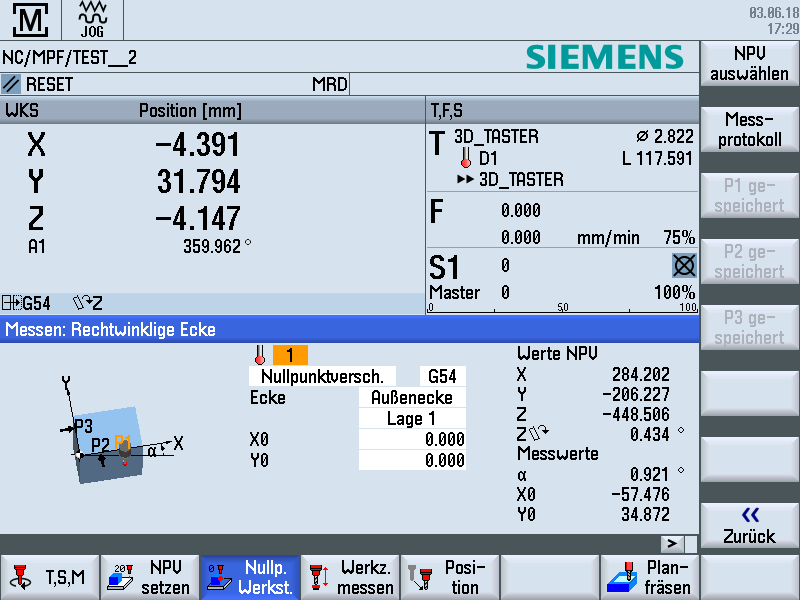
The second step is to set the X and Y-axis zero points. To reach a good result with angle correction, you have to measure at least 3 points.
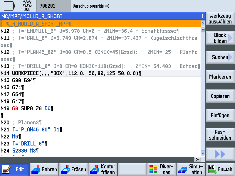
The next step is to mill the parts. :) This is the beginning of my program for the a-side mould. As you can see, 4 tools were used.
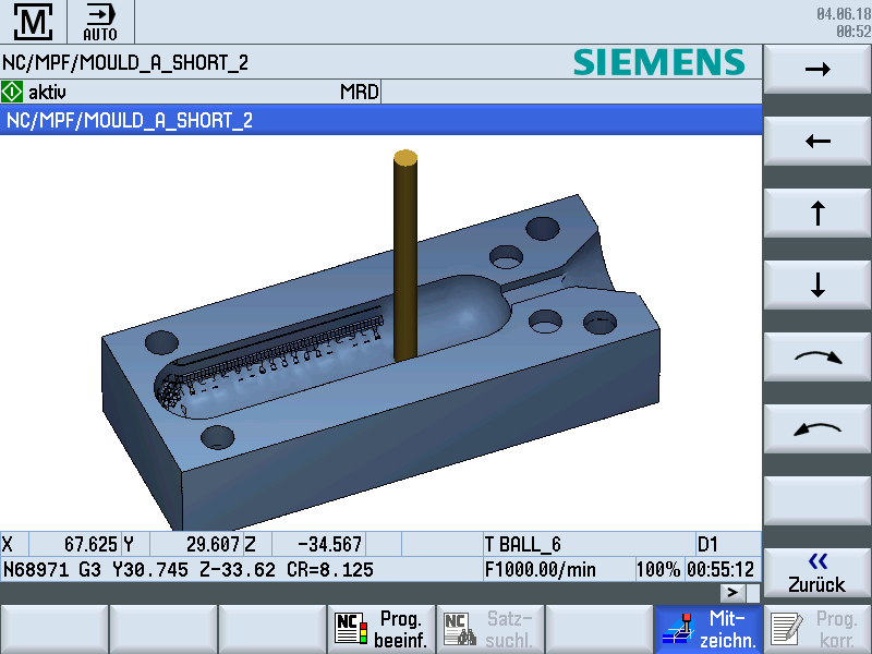
The best way - in my humble opinion - to get a proper overview of what is going on, on your machine, is the included simulation, while milling. This allows you to see which stage of milling runs at the moment.
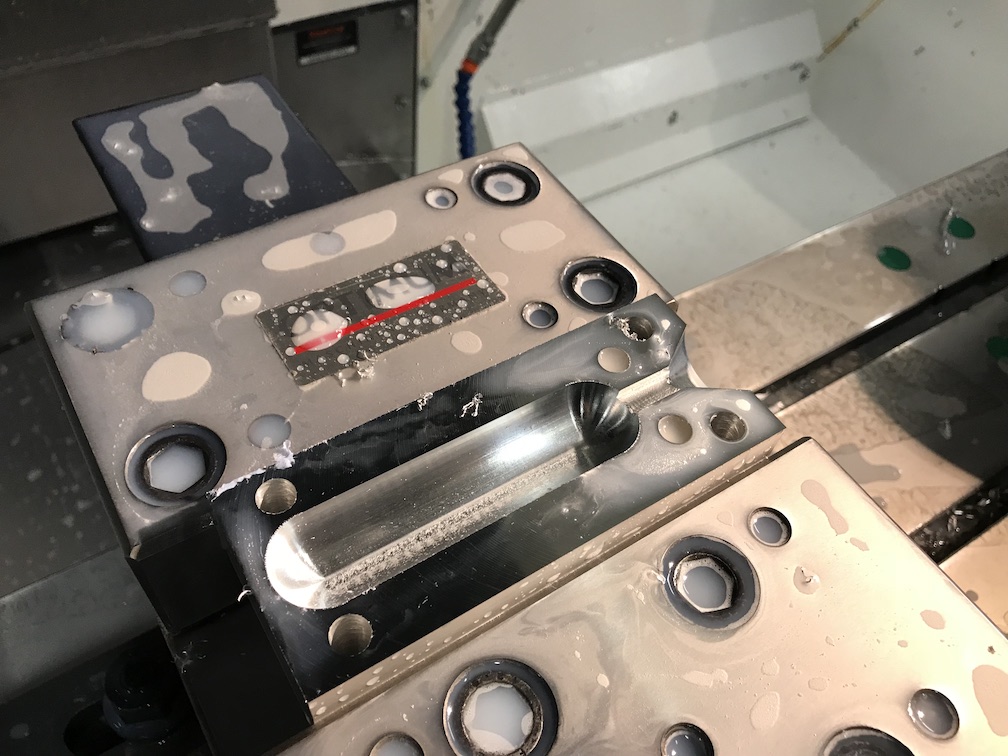
I stopped the machine while milling sometimes, to offer an good overview of the production of my mould. This picture shows the a-side mould after all roughing is done and the finishing started. The tried to rough the negative as much as possible to reduce the load on the radius mill.
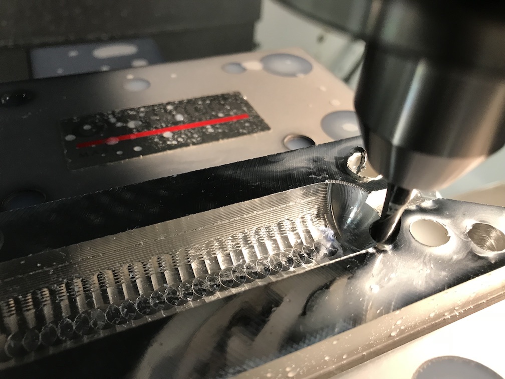
This is a picture of the finished downsprue, while the negative is still rough. Don't let you deceive by the burr. There is a face finishing run at the of the program, to deburr the surface.
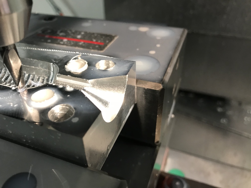
After the a-side mould was finished, the surface as absolutely even and like a mirror. :)
To reach a clean and smooth surface for the negative, I reduced the crossfeed to 0.05 mm. This option needs a lot of time, but gives you a really flat surface.
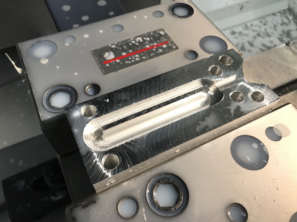
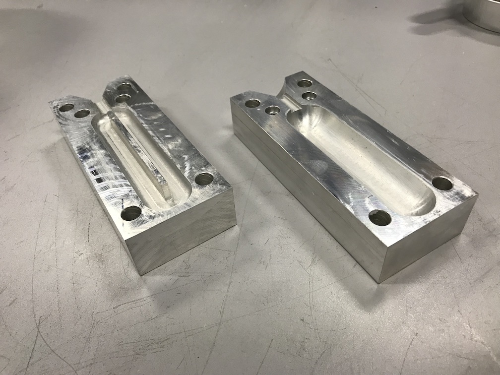
This is the b-side mould after finishing. As you can see, the last tool - the 90° face mill - made a curve around the bar in the middle. This results in a minor worse surface, but it's still better than enough.
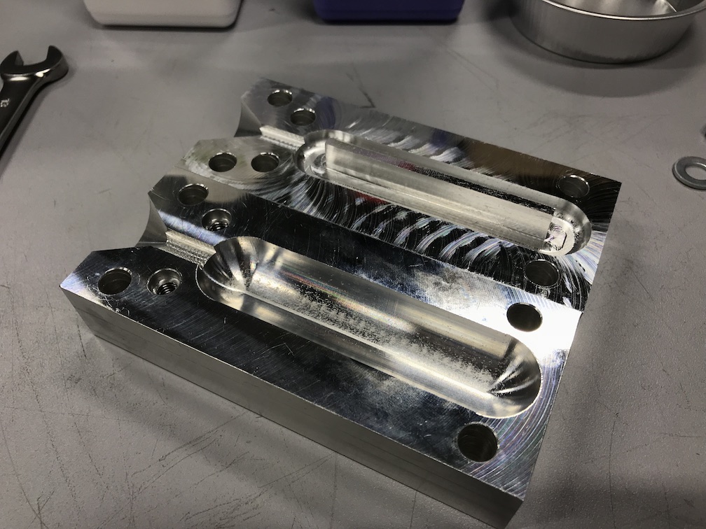
This picture shows both moulds beside each other. It is a nice comparison, to see the difference between the a-side mould with the really clean and symmetrical finish, done with the 45° face mill, and the a bit more rough finish of the b-side mould, done with the 90° face mill. Both moulds were deburred and cleaned from the coolant.
26
Casting the parts:
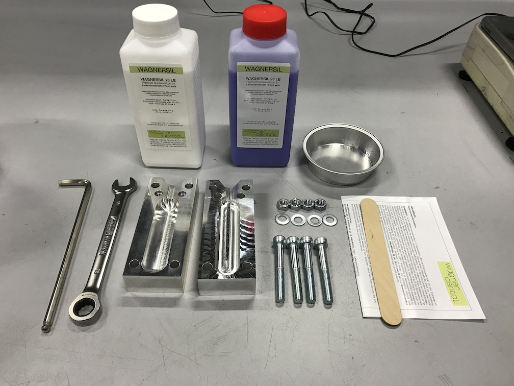
As I wanted some flexible and non-hazardous parts, I decided to use a food-safe silicone, which is easy to use and looks nice. I ordered Wagnersil 26LE which is for dental use. It's a stiff silicone with 26 Shore A - but that's ok!
This is a overview (excluding the vacuum chamber and the scale) of all parts, used for this part of the assignment. Beside some tools and a spatula, there are some M8x60 screws, to secure the mould.
To avoid both moulds from sticking together or the casted parts from not-releasing out of the mould, I used some candle wax as release agent. I rubbed it on the mould surface and polished the wax until it was a smooth surface.
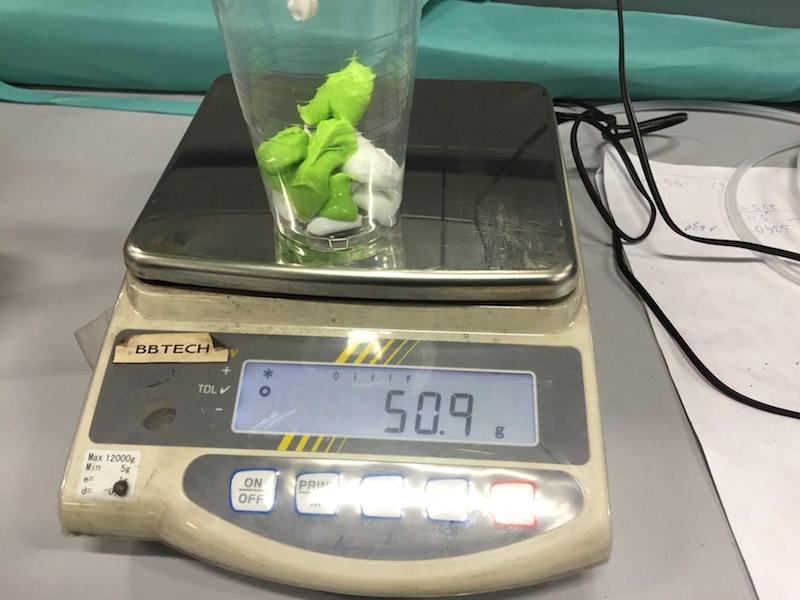
The mixing ratio is 1:1. I mixed 100 g silicone on the scale.
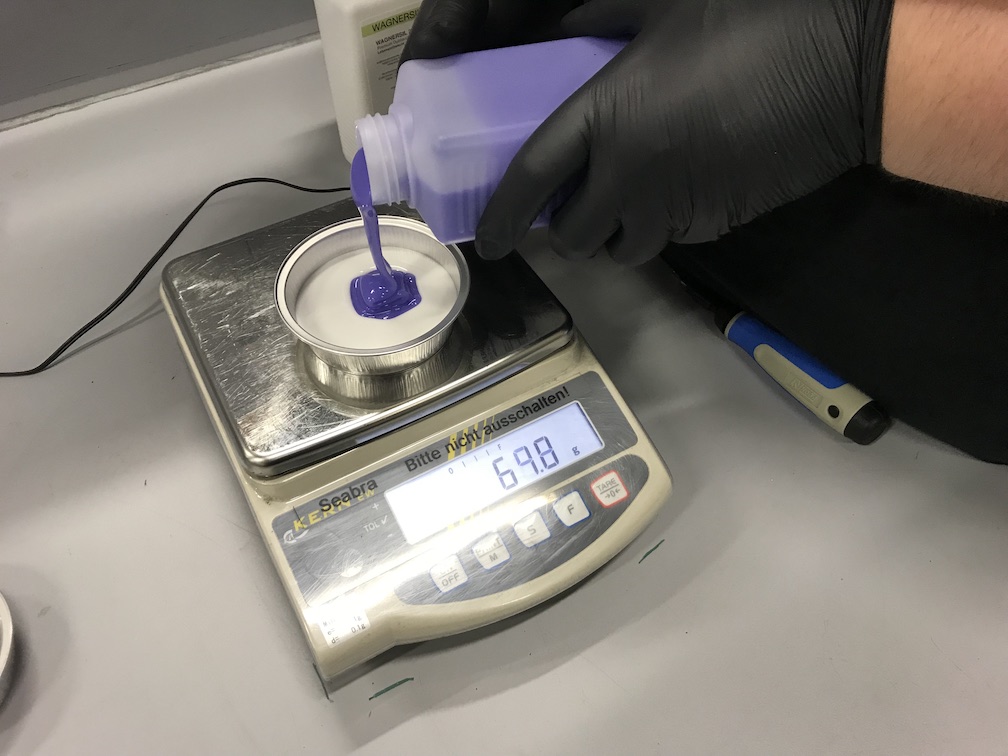
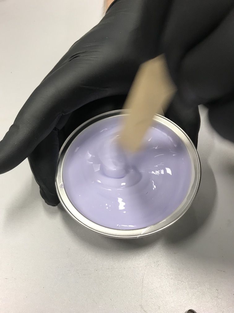
Then you have to stirr a lot... I decided myself to mix more silicone than needed to cast a part, to avoid using non perfectly mixed from bowl's edges.
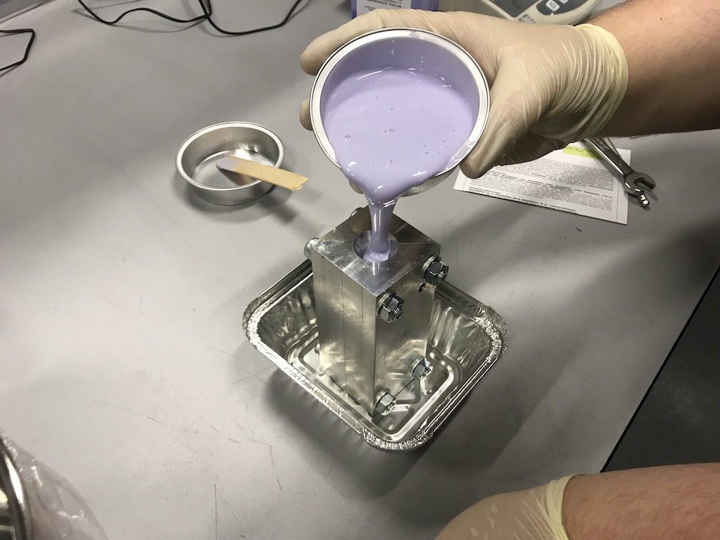
It was time to fill the mould. As the pot life of my silicone is 30 minutes, you don't have to hurry that much. To avoid the table of being super-sticky before being super-flexible, I used another bowl as average jar.
To prevent the cast from air bubbles while curing, I used the high-quality reliable vacuum chamber I bought on Amazon. What do they not have?!
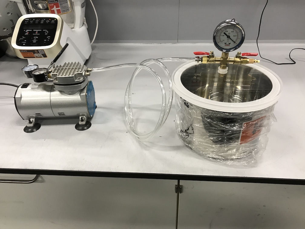
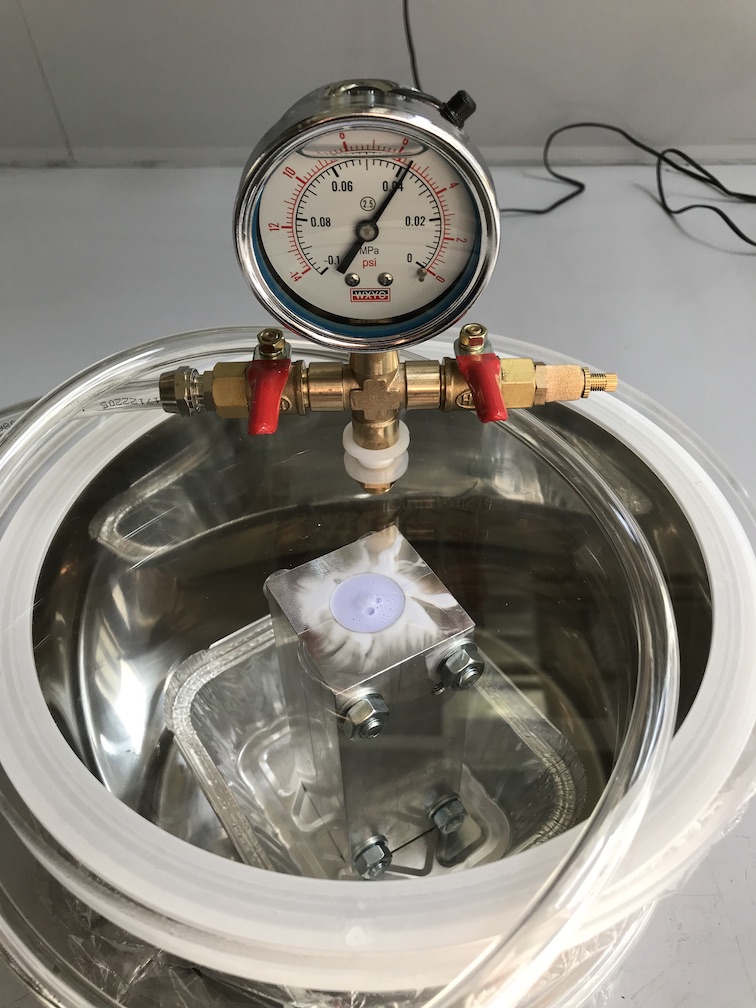
The mould, filled with silicone placed in the chamber under vacuum. As you can see, bubbles releasing out of the silicone. You have to watch the vacuum. If it's too heavy, the silicone will boil. To prevent bubbles in the casted part, you have to release the vacuum and place the filled mould under normal atmosphere, after the most bubbles were gone.
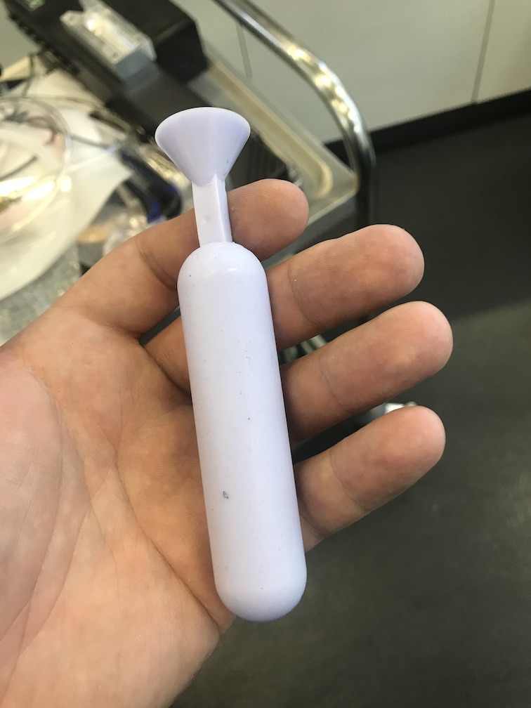
The recommend minimum time before opening the mould is 360 minutes. I let the silicone cure over night for some hours, when I slept. Opening the mould was really easy, as my candle wax appropriate release agent made the job very well.
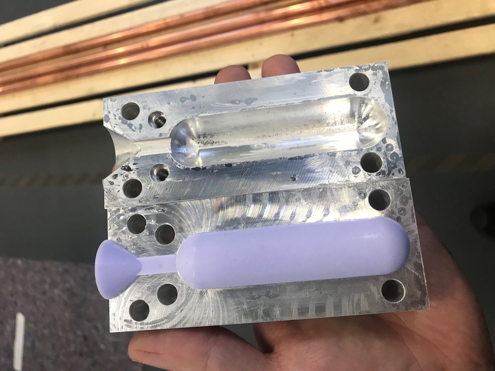
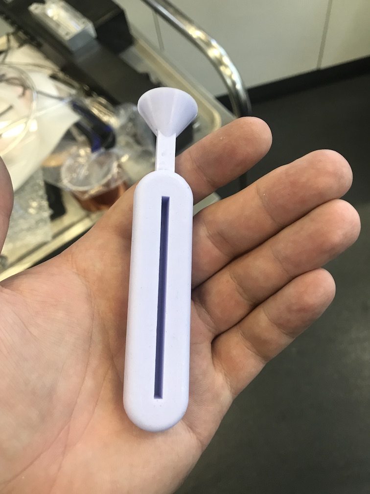
The casted part is very nice. The geometry is clear and sharp, the joint faces are even and smooth, there is no step. Some bubbles are left, but that's ok for the first cast. Even the milled surface is visible. :)
27
Downloads:
Headphone rubber as .ipt
Headphone rubber as .step
Headphone rubber mould A as .ipt
Headphone rubber mould A as .step
Headphone rubber mould B as .ipt
Headphone rubber mould B as .step
Headphone rubber mould A CNC G-Code as .mpf
Headphone rubber mould B CNC G-Code as .mpf

This work by Daniel Bruns is licensed under a Creative Commons Attribution-NonCommercial-ShareAlike 4.0 International License.