01
04
09
10
Introduction
This page is about the software to control the skater-dolly. As I'm not the software-guy, this was a time consuming part for me. I'm writing some lines code from time to time, change firmware on different machine, change the behaviour of CNC postprocessors etc., but I'm not that fast in developing the routines or debugging the code. I would like to thank Florian for the initial help to tame the menu and Christoph for the help while planning the software at night, while eating some burgers with the following after hour debugging party until 5am.
This is the rude flowchart with all needed states while eating our breakfast lunch at night. It's just scribbled with bad handwriting, but it helped a lot to write the program later.
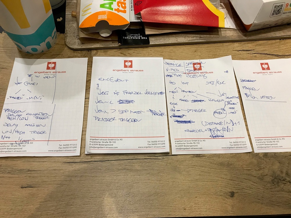
The best way to describe what I've done, is to comment the code here on the page. The program itself is driven by one state variable, which describes the actual state of the skater dolly.
11
Code
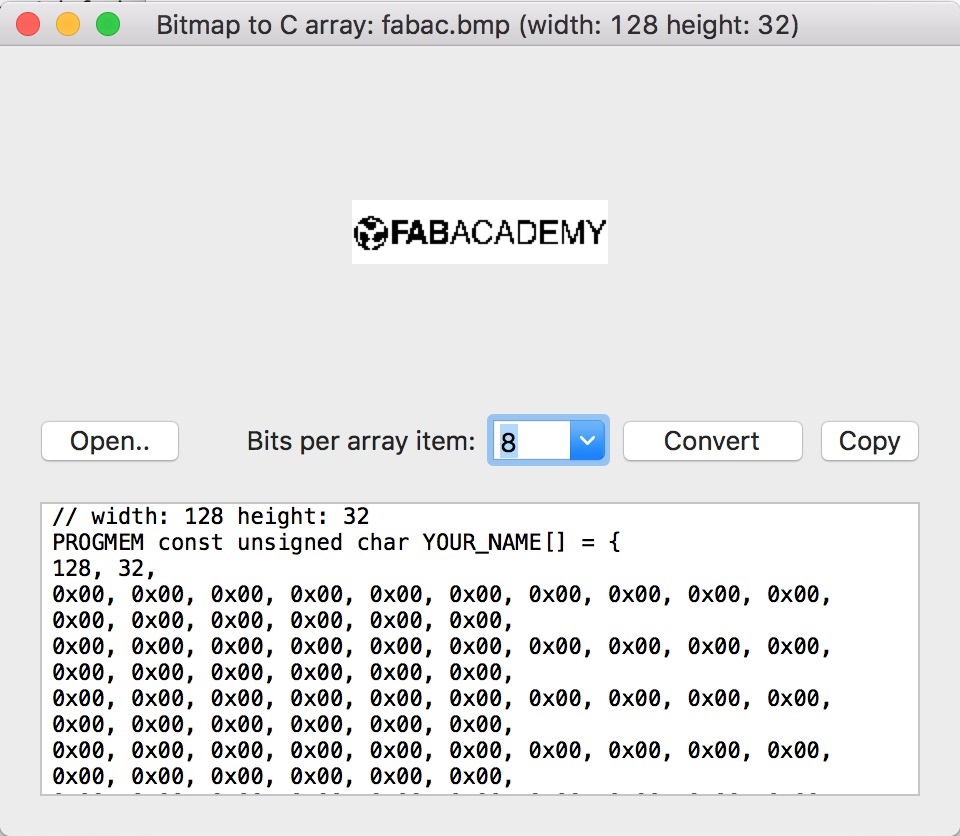
The first part of the software is the initialization.This is the part where the needed libraries were included, the pins were assigned according to the schematic and the variables were declared. Additional to the normal things, I've added the FabAcademy logo as start-up sequence to the code. I've used BitmapToC for this job. It's a very simple and light program to convert pictures.
#include <SPI.h>                        // Include needed Libraries
#include <Wire.h>
#include <Adafruit_GFX.h>
#include <Adafruit_SSD1306.h>
#include <MenuSystem.h>

#define OLED_RESET 4
Adafruit_SSD1306 display(OLED_RESET);

#define NUMFLAKES 10
#define XPOS 0
#define YPOS 1
#define DELTAY 2

#define BTN_LEFT 2
#define BTN_RIGHT 1
#define BTN_UP 4
#define BTN_DOWN 3
#define BTN_PRESS 5

const int BAUDRATE = 9600;              // Baudrate of the serial channel
const int SYSTEM_POWER = 15;            // The system power pin

const int EncMA = 3;                    // Encoder Channel A
const int EncMB = 4;                    // Encoder Channel B
const int motor_direction = 8;          // Motor direction
const int motor_PWM = 10;               // Motor PWM

const int shutter = 16;                 // Camera trigger pin

const int LED_GREEN = 9;                // Green LED
const int LED_RED = 6;                  // Red LED
const int LED_BLUE = 11;                // Blue LED

const int BUTTON_DOWN = 5;
const int BUTTON_UP = 7;
const int BUTTON_RIGHT = 21;
const int BUTTON_LEFT = 20;
const int BUTTON_PRESS = 2;

void buttonDown(void);
void buttonUp(void);
void buttonRight(void);
void buttonLeft(void);
void buttonPress(void);
void moveSkater(void);
void waitTime(void);
void trigger(void);


int PWM_speed = 75;                     // PWM speed | Pre: 75
int drivingState = 0;                   // Driving state
long distance = 100;                    // Full distance travel in cm | Pre: 100cm
int n_pics = 300;                       // Number of pictures | Pre: 300 pictures
int act_pics = 0;                       // Actual number of pictures variable
long waitingTime = 1000;                // Waiting time in seconds | Pre: 1 second
long segment = 0;                       // Distance segment
long destination = 0;                   // Destination in Encoder Counts

int mot_dir = 0;                        // Motor direction variable


long EncCount = 0;                      // Variable to store Encoder pulses

int currentMenuNr = 0;
bool buttonPressed = false;             // Button press indicator for register only single inputs

  PROGMEM const unsigned char FabAcademy_bmp[] = {
    0x00, 0x00, 0x00, 0x00, 0x00, 0x00, 0x00, 0x00, 0x00, 0x00, 0x00, 0x00, 0x00, 0x00, 0x00, 0x00,
    0x00, 0x00, 0x00, 0x00, 0x00, 0x00, 0x00, 0x00, 0x00, 0x00, 0x00, 0x00, 0x00, 0x00, 0x00, 0x00,
    0x00, 0x00, 0x00, 0x00, 0x00, 0x00, 0x00, 0x00, 0x00, 0x00, 0x00, 0x00, 0x00, 0x00, 0x00, 0x00,
    0x00, 0x00, 0x00, 0x00, 0x00, 0x00, 0x00, 0x00, 0x00, 0x00, 0x00, 0x00, 0x00, 0x00, 0x00, 0x00,
    0x00, 0x00, 0x00, 0x00, 0x00, 0x00, 0x00, 0x00, 0x00, 0x00, 0x00, 0x00, 0x00, 0x00, 0x00, 0x00,
    0x00, 0x00, 0x00, 0x00, 0x00, 0x00, 0x00, 0x00, 0x00, 0x00, 0x00, 0x00, 0x00, 0x00, 0x00, 0x00,
    0x00, 0x00, 0x00, 0x00, 0x00, 0x00, 0x00, 0x00, 0x00, 0x00, 0x00, 0x00, 0x00, 0x00, 0x00, 0x00,
    0x00, 0x00, 0x00, 0x00, 0x00, 0x00, 0x00, 0x00, 0x00, 0x00, 0x00, 0x00, 0x00, 0x00, 0x00, 0x00,
    0x00, 0xe0, 0x00, 0x00, 0x00, 0x00, 0x00, 0x00, 0x00, 0x00, 0x00, 0x00, 0x00, 0x00, 0x00, 0x00,
    0x07, 0xbc, 0x00, 0x00, 0x00, 0x00, 0x00, 0x00, 0x00, 0x00, 0x00, 0x00, 0x00, 0x00, 0x00, 0x00,
    0x0f, 0x0e, 0x0f, 0xf1, 0xc1, 0xfc, 0x06, 0x01, 0xf0, 0x18, 0x1f, 0x83, 0xfe, 0x60, 0x36, 0x06,
    0x1f, 0xf3, 0x0f, 0xf3, 0xc1, 0xff, 0x07, 0x03, 0x18, 0x1c, 0x1f, 0xe3, 0xfe, 0x60, 0x73, 0x06,
    0x03, 0xf0, 0x0e, 0x03, 0xe1, 0x87, 0x05, 0x06, 0x0c, 0x14, 0x10, 0x33, 0x00, 0x70, 0x71, 0x0c,
    0x21, 0xf0, 0x8e, 0x03, 0xe1, 0x83, 0x0d, 0x84, 0x04, 0x36, 0x10, 0x33, 0x00, 0x50, 0x71, 0x88,
    0x60, 0xe0, 0xce, 0x07, 0x61, 0x87, 0x09, 0x8c, 0x00, 0x26, 0x10, 0x13, 0x00, 0x50, 0xf0, 0xd8,
    0x60, 0x00, 0xcf, 0xf6, 0x71, 0xfe, 0x08, 0x8c, 0x00, 0x22, 0x10, 0x13, 0xfc, 0x58, 0xb0, 0xf0,
    0x6e, 0x0f, 0xcf, 0xf6, 0x71, 0xff, 0x18, 0xcc, 0x00, 0x63, 0x10, 0x13, 0xfc, 0x48, 0xb0, 0x70,
    0x6f, 0x1f, 0xce, 0x0f, 0xf1, 0x83, 0x1f, 0xcc, 0x00, 0x7f, 0x10, 0x13, 0x00, 0x49, 0xb0, 0x60,
    0x6f, 0x1f, 0xce, 0x0f, 0xf9, 0x83, 0x30, 0x4c, 0x04, 0xc1, 0x10, 0x33, 0x00, 0x4d, 0x30, 0x60,
    0x2f, 0xbe, 0x8e, 0x0f, 0xf9, 0x87, 0x30, 0x66, 0x0c, 0xc1, 0x90, 0x33, 0x00, 0x47, 0x30, 0x60,
    0x27, 0x1c, 0x8e, 0x1c, 0x19, 0xff, 0x20, 0x67, 0x18, 0x81, 0x90, 0xe3, 0x00, 0x47, 0x30, 0x60,
    0x16, 0x01, 0x0e, 0x18, 0x1d, 0xfe, 0x60, 0x21, 0xf1, 0x80, 0x9f, 0xc3, 0xfe, 0x46, 0x30, 0x60,
    0x1e, 0x07, 0x00, 0x00, 0x00, 0x00, 0x00, 0x00, 0x00, 0x00, 0x00, 0x00, 0x00, 0x00, 0x00, 0x00,
    0x07, 0x1c, 0x00, 0x00, 0x00, 0x00, 0x00, 0x00, 0x00, 0x00, 0x00, 0x00, 0x00, 0x00, 0x00, 0x00,
    0x03, 0xb8, 0x00, 0x00, 0x00, 0x00, 0x00, 0x00, 0x00, 0x00, 0x00, 0x00, 0x00, 0x00, 0x00, 0x00,
    0x00, 0x00, 0x00, 0x00, 0x00, 0x00, 0x00, 0x00, 0x00, 0x00, 0x00, 0x00, 0x00, 0x00, 0x00, 0x00,
    0x00, 0x00, 0x00, 0x00, 0x00, 0x00, 0x00, 0x00, 0x00, 0x00, 0x00, 0x00, 0x00, 0x00, 0x00, 0x00,
    0x00, 0x00, 0x00, 0x00, 0x00, 0x00, 0x00, 0x00, 0x00, 0x00, 0x00, 0x00, 0x00, 0x00, 0x00, 0x00,
    0x00, 0x00, 0x00, 0x00, 0x00, 0x00, 0x00, 0x00, 0x00, 0x00, 0x00, 0x00, 0x00, 0x00, 0x00, 0x00,
    0x00, 0x00, 0x00, 0x00, 0x00, 0x00, 0x00, 0x00, 0x00, 0x00, 0x00, 0x00, 0x00, 0x00, 0x00, 0x00,
    0x00, 0x00, 0x00, 0x00, 0x00, 0x00, 0x00, 0x00, 0x00, 0x00, 0x00, 0x00, 0x00, 0x00, 0x00, 0x00,
    0x00, 0x00, 0x00, 0x00, 0x00, 0x00, 0x00, 0x00, 0x00, 0x00, 0x00, 0x00, 0x00, 0x00, 0x00, 0x00
  };
The second part is the 'setup'. In this part the display and board will get it's initialization after and while the start-up. Clear and rotate the display, set the pinmodes for every pin and even the condition on start-up, to ensure the LEDs are off etc.. Even the internal pullup resistors were set. The serial connection with the pre-defined baudrate and the interrupt were set. The last lines are calling the boot sequence.
void setup() {


  // Init display

  display.begin(SSD1306_SWITCHCAPVCC, 0x3C);    // Display initialize with the I2C addr 0x3C (for the 128x32)
  display.setRotation(2);                       // Rotate Display upside down
  display.clearDisplay();                       // Initial clear of the display

  pinMode(SYSTEM_POWER,OUTPUT);                 // Set SysOn PIN as output
  digitalWrite(SYSTEM_POWER,HIGH);              // Set SysOn HIGH to power PCB

  pinMode(EncMA, INPUT);                        // Set Encoder Channel A as input
  pinMode(EncMB, INPUT);                        // Set Encoder Channel B as input
  pinMode(motor_direction, OUTPUT);             // Set DirectionMOT as output
  pinMode(motor_PWM, OUTPUT);                   // Set PWM_MOT as output

  pinMode(shutter, OUTPUT);                     // Set the shutter pin as Output

  pinMode(BUTTON_DOWN, INPUT_PULLUP);
  pinMode(BUTTON_UP, INPUT_PULLUP);
  pinMode(BUTTON_PRESS, INPUT_PULLUP);

  // Init the Buttons of the RGB LED
  pinMode(LED_GREEN, OUTPUT);
  pinMode(LED_RED, OUTPUT);
  pinMode(LED_BLUE, OUTPUT);

  digitalWrite(LED_GREEN, HIGH);                // Initial LED turn off
  digitalWrite(LED_RED, HIGH);                  // Initial LED turn off
  digitalWrite(LED_BLUE, HIGH);                 // Initial LED turn off
  digitalWrite(shutter, LOW);                   // Initial shutter disengage

  attachInterrupt(1, encoderEvent, CHANGE);     // initialize interrupt

  Serial.begin(BAUDRATE);                       // Init serial communication

  // init done

  bootSequence();
}
The loop is the normal program routine which calls the drawMenu function with the according menu number and - if the skater is in the capturing mode - calls the concurring functions in a fixed cycle, until the capturing is finished. This function will be executed constantly, by default.
/*  Driving states:
 *   1: trigger
 *   2: waiting
 *   3: move
 *   0: menu
 */

void loop() {

  drawMenu(currentMenuNr);

  switch (readButtonState()) {
    case BTN_LEFT:
      buttonLeft();
      break;

    case BTN_RIGHT:
      buttonRight();
      break;

    case BTN_DOWN:
      buttonDown();
      break;

    case BTN_UP:
      buttonUp();
      break;

    case BTN_PRESS:
      buttonPress();
      break;
  }

  switch (drivingState){
    case 1:
      trigger();
    break;

    case 2:
      waitTime();
    break;

    case 3:
      moveSkater();
    break;
  }
}
This is the whole menu with all entrys. The menu entrys are calling different pre-defined variables from above, to manipulate them by the user before starting the skater.
/**
 * Draw the menu entry
 */
void drawMenu(int menuNr){
  switch(menuNr){
    case 0:
      // Shutdown System
      display.clearDisplay();
      display.setCursor(0,8);
      display.setTextSize(2);
      display.setTextColor(WHITE);
      display.println("Shutdown");
      display.display();
      display.clearDisplay();
      break;

    case 1:
      // Set drive distance
      display.clearDisplay();
      display.setCursor(0,8);
      display.setTextSize(2);
      display.setTextColor(WHITE);
      display.print("d ");
      display.print(distance);
      display.println(" cm");
      display.display();
      break;

    case 2:
      // Set n pictures
      display.clearDisplay();
      display.setCursor(0,8);
      display.setTextSize(2);
      display.setTextColor(WHITE);
      display.print("n ");
      display.println(n_pics);
      display.display();
      break;

    case 3:
      // Set waiting time
      display.clearDisplay();
      display.setCursor(0,8);
      display.setTextSize(2);
      display.setTextColor(WHITE);
      display.print("t ");
      display.print(waitingTime);
      display.println(" ms");
      display.display();
      break;

    case 4:
      // Set direction
      display.clearDisplay();
      display.setCursor(0,8);
      display.setTextSize(2);
      display.setTextColor(WHITE);
      display.print("dir ");
      display.println(mot_dir);
      display.display();
      break;

    case 5:
      // Set PWM
      display.clearDisplay();
      display.setCursor(0,8);
      display.setTextSize(2);
      display.setTextColor(WHITE);
      display.print("PWM ");
      display.println(PWM_speed);
      display.display();
      break;

    case 6:
      // Start
      display.clearDisplay();
      display.setCursor(0,8);
      display.setTextSize(2);
      display.setTextColor(WHITE);
      display.println("Start");
      display.display();
      break;

     case 99:
      // Display off
      display.clearDisplay();
      display.display();
      break;
  }
}
The Encoder Event is the really important parts which counts the encoder signals from the motor. Every time the encoder outputs a signal, the interrupt will be triggered, which ends in calling this function. This function is able to count up and down, to allow the skater to move controlled in both directions. When the skater reaches the set segment (part of the whole distance devided through the number of pictures in encoder counts) counts, it stops the motor PWM and sets the skater into the driving state '1', this is the trigger state.
void encoderEvent() {
  if (digitalRead(EncMA) == HIGH) {
    if (digitalRead(EncMB) == LOW) {
      EncCount++;
    } else {
      EncCount--;
    }
  } else {
    if (digitalRead(EncMB) == LOW) {
      EncCount--;
    } else {
      EncCount++;
    }
  }
  if (mot_dir==1){
    if (EncCount<segment){
      drivingState=3;
    } else if (drivingState == 3){
       analogWrite(motor_PWM, 0);
       drivingState=1;
       Serial.println(EncCount);
    }
  } else {
     if (EncCount>segment){
      drivingState=3;
    } else if (drivingState == 3){
      analogWrite(motor_PWM, 0);
      drivingState=1;
      Serial.println(EncCount);
    }
  }
}
This is the trigger function. The function waits for 100 ms, as the motor is coasting after stopping. The camera shutter will be triggered, hold for 250 ms to ensure the camera will recognize it and then released. To count the captured pictures, another variable 'act_pics' will be raised. The end condition is to set the skater to the driving state '2' which is 'waiting'.
void trigger(){
  delay(100); // Wait for the skater to stop
  digitalWrite(shutter, HIGH); // Shutter engage
  delay(250);  // Wait for the camera shutter
  digitalWrite(shutter, LOW); // Shutter disengage
  delay(10); // Wait for the mirror to close
  act_pics++; // Count the amount of pictures up
  drivingState=2;
}
This 'waitTime' function has some debugging functions left, which are unnecessary for the normal use, but were helpful for the first start-up. This functions waits for the pre-defined time, which will be set as value in the menu before starting the capturing. This function does the calculation for the segment distance and compares if there are still pictures must be captured. If yes, the function sets the driving state to '3' which is 'move', if not, it enters the menu.
void waitTime(){
 Serial.println("Waiting...");
   Serial.print("EncCount: ");
  Serial.println(EncCount);
  delay(waitingTime);
  if (mot_dir==1){
    if (act_pics<n_pics){
      segment+=destination/n_pics;
      drivingState=3;
    } else {
      drivingState=0;
      currentMenuNr=0;
    }
  } else {
     if (act_pics<n_pics){
      segment+=destination/n_pics;
      drivingState=3;
    } else {
      drivingState=0;
      currentMenuNr=0;
    }
  }
}
The 'moveSkater' function sets the motor direction. After this, it sets the motor PWM with the, in the menu pre-defined PWM duty cycle. This function does not set any driving state, as the interrupt will stop by itself when the pre set segment distance is reached.
void moveSkater(){
 digitalWrite(motor_direction, mot_dir);
 analogWrite(motor_PWM, PWM_speed);
}
The 'bootSequence' function clears the display, shows the start-up logo, calls the LED pulse function for 2000 ms with the color green and clears the display again, before the loop enters the menu by itself.
void bootSequence(){
  display.clearDisplay();   // clears the screen and buffer
  display.drawBitmap(0, 0,  FabAcademy_bmp, 128, 32, 1);
  led_pulse(1, 2000);  // pulse the led green for starting
  display.display();
  delay(2000);        // wait 2 seconds

  // clear the display again
  display.clearDisplay();
  display.display();
}
This is 'shutdownSequence' function, which is needed to shutdown the board without consuming any(!) capacity. This function inverts the display, pulses the LED red for 2000 ms and releases the SysOn pin, which is necessary to hold the MOSFET in the suicide-circuit.
// Sequence to shut down the board
void shutdownSequence(){
  display.invertDisplay(true);
  led_pulse(0, 2000);  // pulse the led red for shutdown
  digitalWrite(SYSTEM_POWER, LOW);
}
This is a simple function which pulses the LED via PWM for a pre-defined time in a pre-defined color.
/* flashes a led of color
    0 = red
    1 = green
    2 = blue
    on and of for milliseconds
*/
void led_pulse(int color, int ms){

  int brightness = 254;
  int summand = -1;
  int delayTime = ms / 512;
  int ledColor;             // color of the LED to control

  switch (color) {
  case 2:
    ledColor = LED_BLUE;
    break;
  case 1:
    ledColor = LED_GREEN;
    break;
  default:
    ledColor = LED_RED;
}

  while(brightness <= 255){
    analogWrite(ledColor, brightness);
    if(brightness == 0){
      summand *= -1;
    }
    brightness += summand;
    delay(delayTime);
  }
}
This function is for debouncing the buttons effectively. It only returns one press, after the button is released.
/*
 * Read the button pins and return an integer that tells which button was pressed
 *
 *  0 = no input
 *  1 = left
 *  2 = right
 *  3 = up
 *  4 = down
 *  5 = button press
 */
int readButtonState(){
  int ret = 0;

  if (!digitalRead(BUTTON_UP) ) ret = 3;
  if (!digitalRead(BUTTON_DOWN) ) ret = 4;
  if (!digitalRead(BUTTON_PRESS) ) ret = 5;

  // Read the buttons on analog pin. Pressed when 0
  if(!analogRead(BUTTON_LEFT)) ret = 1;
  if(!analogRead(BUTTON_RIGHT)) ret = 2;

  if(buttonPressed && ret == 0) {    // Reset again when button released
    buttonPressed = false;
    ret = 0;
  }if(buttonPressed && ret != 0){   // Don't count presses twice
    ret = 0;
  }if(ret != 0){                            // Normal press return
    buttonPressed = true;
    //led_pulse(2, 1000);
  };

  return ret;
}
These button related functions decide what to do when a button is pressed, according to the actual menu. Here were the steps for increasing or decreasing values set.
void buttonDown(){
  switch (currentMenuNr){
    case 1:
     distance = distance-10;
     if (distance<0){
      distance=0;
     }
    break;

    case 2:
    n_pics = n_pics-10;
    if (n_pics<0){
      n_pics=1;
    }
    break;

    case 3:
      waitingTime = waitingTime-500;
      if (waitingTime<0){
        waitingTime=0;
      }
      break;

    case 4:
      mot_dir=0;
      digitalWrite(motor_direction, 0);
    break;

    case 5:
      PWM_speed--;
      if (PWM_speed<0){
        PWM_speed=0;
      }
      break;
  }
}

void buttonUp(){
  switch (currentMenuNr){
    case 1:
     distance = distance+10;
     if (distance>500){
      distance=500;
     }
    break;

    case 2:
    n_pics = n_pics+10;
    if (n_pics>3000){
      n_pics=3000;
    }
    break;

    case 3:
      waitingTime = waitingTime+500;
      if (waitingTime>60000){
        waitingTime=60000;
      }
      break;

    case 4:
      mot_dir=1;
      digitalWrite(motor_direction, 1);
    break;

    case 5:
      PWM_speed = PWM_speed+10;
      if (PWM_speed>255){
        PWM_speed=255;
      }
      break;
  }
}

void buttonLeft(){
  currentMenuNr--;
  if (currentMenuNr<0){
    currentMenuNr=6;
  }
}

void buttonRight(){
  currentMenuNr++;
  if (currentMenuNr>6){
    currentMenuNr=0;
  }
}
This is the same like the functions above but for pressing the button, instead for a direction. This function calculates the destination in encoder steps from the set distance. After calculating the distance, the display will enter a 'dark' mode and wait for 2500 ms to ensure a start without vibrations caused by the user while pressing the button. If the menu is in the 'Shutdown' case, a button press will call the shutdown sequence.
void buttonPress(){
  switch (currentMenuNr){
    case 0:
      shutdownSequence();
    break;

    case 6:
      destination = distance * 5550; // diameter: 11mm*pi=34,6mm -> 38400 (64CPR*600:1) 38400/3,46->11100
      only 1/2 is counted -> 5550

   if (mot_dir==0){
        destination = destination*-1;
      }
      segment = 0;
      currentMenuNr=99;
      delay(2500);                  // Delay as anti-vibration time
      drivingState=1;
      Serial.print("dest: ");
      Serial.println(destination);
      Serial.print("dist: ");
      Serial.println(distance);
    break;
  }
}
Code as plain text:
#include <SPI.h>                        // Include needed Libraries
#include <Wire.h>
#include <Adafruit_GFX.h>
#include <Adafruit_SSD1306.h>
#include <MenuSystem.h>

#define OLED_RESET 4
Adafruit_SSD1306 display(OLED_RESET);

#define NUMFLAKES 10
#define XPOS 0
#define YPOS 1
#define DELTAY 2

#define BTN_LEFT 2
#define BTN_RIGHT 1
#define BTN_UP 4
#define BTN_DOWN 3
#define BTN_PRESS 5

const int BAUDRATE = 9600;              // Baudrate of the serial channel
const int SYSTEM_POWER = 15;            // The system power pin

const int EncMA = 3;                    // Encoder Channel A
const int EncMB = 4;                    // Encoder Channel B
const int motor_direction = 8;          // Motor direction
const int motor_PWM = 10;               // Motor PWM

const int shutter = 16;                 // Camera trigger pin

const int LED_GREEN = 9;                // Green LED
const int LED_RED = 6;                  // Red LED
const int LED_BLUE = 11;                // Blue LED

const int BUTTON_DOWN = 5;
const int BUTTON_UP = 7;
const int BUTTON_RIGHT = 21;
const int BUTTON_LEFT = 20;
const int BUTTON_PRESS = 2;

void buttonDown(void);
void buttonUp(void);
void buttonRight(void);
void buttonLeft(void);
void buttonPress(void);
void moveSkater(void);
void waitTime(void);
void trigger(void);


int PWM_speed = 75;                     // PWM speed | Pre: 75
int drivingState = 0;                   // Driving state
long distance = 100;                    // Full distance travel in cm | Pre: 100cm
int n_pics = 300;                       // Number of pictures | Pre: 300 pictures
int act_pics = 0;                       // Actual number of pictures variable
long waitingTime = 1000;                // Waiting time in seconds | Pre: 1 second
long segment = 0;                       // Distance segment
long destination = 0;                   // Destination in Encoder Counts

int mot_dir = 0;                        // Motor direction variable


long EncCount = 0;                      // Variable to store Encoder pulses

int currentMenuNr = 0;
bool buttonPressed = false;             // Button press indicator for register only single inputs

  PROGMEM const unsigned char FabAcademy_bmp[] = {
    0x00, 0x00, 0x00, 0x00, 0x00, 0x00, 0x00, 0x00, 0x00, 0x00, 0x00, 0x00, 0x00, 0x00, 0x00, 0x00,
    0x00, 0x00, 0x00, 0x00, 0x00, 0x00, 0x00, 0x00, 0x00, 0x00, 0x00, 0x00, 0x00, 0x00, 0x00, 0x00,
    0x00, 0x00, 0x00, 0x00, 0x00, 0x00, 0x00, 0x00, 0x00, 0x00, 0x00, 0x00, 0x00, 0x00, 0x00, 0x00,
    0x00, 0x00, 0x00, 0x00, 0x00, 0x00, 0x00, 0x00, 0x00, 0x00, 0x00, 0x00, 0x00, 0x00, 0x00, 0x00,
    0x00, 0x00, 0x00, 0x00, 0x00, 0x00, 0x00, 0x00, 0x00, 0x00, 0x00, 0x00, 0x00, 0x00, 0x00, 0x00,
    0x00, 0x00, 0x00, 0x00, 0x00, 0x00, 0x00, 0x00, 0x00, 0x00, 0x00, 0x00, 0x00, 0x00, 0x00, 0x00,
    0x00, 0x00, 0x00, 0x00, 0x00, 0x00, 0x00, 0x00, 0x00, 0x00, 0x00, 0x00, 0x00, 0x00, 0x00, 0x00,
    0x00, 0x00, 0x00, 0x00, 0x00, 0x00, 0x00, 0x00, 0x00, 0x00, 0x00, 0x00, 0x00, 0x00, 0x00, 0x00,
    0x00, 0xe0, 0x00, 0x00, 0x00, 0x00, 0x00, 0x00, 0x00, 0x00, 0x00, 0x00, 0x00, 0x00, 0x00, 0x00,
    0x07, 0xbc, 0x00, 0x00, 0x00, 0x00, 0x00, 0x00, 0x00, 0x00, 0x00, 0x00, 0x00, 0x00, 0x00, 0x00,
    0x0f, 0x0e, 0x0f, 0xf1, 0xc1, 0xfc, 0x06, 0x01, 0xf0, 0x18, 0x1f, 0x83, 0xfe, 0x60, 0x36, 0x06,
    0x1f, 0xf3, 0x0f, 0xf3, 0xc1, 0xff, 0x07, 0x03, 0x18, 0x1c, 0x1f, 0xe3, 0xfe, 0x60, 0x73, 0x06,
    0x03, 0xf0, 0x0e, 0x03, 0xe1, 0x87, 0x05, 0x06, 0x0c, 0x14, 0x10, 0x33, 0x00, 0x70, 0x71, 0x0c,
    0x21, 0xf0, 0x8e, 0x03, 0xe1, 0x83, 0x0d, 0x84, 0x04, 0x36, 0x10, 0x33, 0x00, 0x50, 0x71, 0x88,
    0x60, 0xe0, 0xce, 0x07, 0x61, 0x87, 0x09, 0x8c, 0x00, 0x26, 0x10, 0x13, 0x00, 0x50, 0xf0, 0xd8,
    0x60, 0x00, 0xcf, 0xf6, 0x71, 0xfe, 0x08, 0x8c, 0x00, 0x22, 0x10, 0x13, 0xfc, 0x58, 0xb0, 0xf0,
    0x6e, 0x0f, 0xcf, 0xf6, 0x71, 0xff, 0x18, 0xcc, 0x00, 0x63, 0x10, 0x13, 0xfc, 0x48, 0xb0, 0x70,
    0x6f, 0x1f, 0xce, 0x0f, 0xf1, 0x83, 0x1f, 0xcc, 0x00, 0x7f, 0x10, 0x13, 0x00, 0x49, 0xb0, 0x60,
    0x6f, 0x1f, 0xce, 0x0f, 0xf9, 0x83, 0x30, 0x4c, 0x04, 0xc1, 0x10, 0x33, 0x00, 0x4d, 0x30, 0x60,
    0x2f, 0xbe, 0x8e, 0x0f, 0xf9, 0x87, 0x30, 0x66, 0x0c, 0xc1, 0x90, 0x33, 0x00, 0x47, 0x30, 0x60,
    0x27, 0x1c, 0x8e, 0x1c, 0x19, 0xff, 0x20, 0x67, 0x18, 0x81, 0x90, 0xe3, 0x00, 0x47, 0x30, 0x60,
    0x16, 0x01, 0x0e, 0x18, 0x1d, 0xfe, 0x60, 0x21, 0xf1, 0x80, 0x9f, 0xc3, 0xfe, 0x46, 0x30, 0x60,
    0x1e, 0x07, 0x00, 0x00, 0x00, 0x00, 0x00, 0x00, 0x00, 0x00, 0x00, 0x00, 0x00, 0x00, 0x00, 0x00,
    0x07, 0x1c, 0x00, 0x00, 0x00, 0x00, 0x00, 0x00, 0x00, 0x00, 0x00, 0x00, 0x00, 0x00, 0x00, 0x00,
    0x03, 0xb8, 0x00, 0x00, 0x00, 0x00, 0x00, 0x00, 0x00, 0x00, 0x00, 0x00, 0x00, 0x00, 0x00, 0x00,
    0x00, 0x00, 0x00, 0x00, 0x00, 0x00, 0x00, 0x00, 0x00, 0x00, 0x00, 0x00, 0x00, 0x00, 0x00, 0x00,
    0x00, 0x00, 0x00, 0x00, 0x00, 0x00, 0x00, 0x00, 0x00, 0x00, 0x00, 0x00, 0x00, 0x00, 0x00, 0x00,
    0x00, 0x00, 0x00, 0x00, 0x00, 0x00, 0x00, 0x00, 0x00, 0x00, 0x00, 0x00, 0x00, 0x00, 0x00, 0x00,
    0x00, 0x00, 0x00, 0x00, 0x00, 0x00, 0x00, 0x00, 0x00, 0x00, 0x00, 0x00, 0x00, 0x00, 0x00, 0x00,
    0x00, 0x00, 0x00, 0x00, 0x00, 0x00, 0x00, 0x00, 0x00, 0x00, 0x00, 0x00, 0x00, 0x00, 0x00, 0x00,
    0x00, 0x00, 0x00, 0x00, 0x00, 0x00, 0x00, 0x00, 0x00, 0x00, 0x00, 0x00, 0x00, 0x00, 0x00, 0x00,
    0x00, 0x00, 0x00, 0x00, 0x00, 0x00, 0x00, 0x00, 0x00, 0x00, 0x00, 0x00, 0x00, 0x00, 0x00, 0x00
  };

void setup() {


  // Init display

  display.begin(SSD1306_SWITCHCAPVCC, 0x3C);    // Display initialize with the I2C addr 0x3C (for the 128x32)
  display.setRotation(2);                       // Rotate Display upside down
  display.clearDisplay();                       // Initial clear of the display

  pinMode(SYSTEM_POWER,OUTPUT);                 // Set SysOn PIN as output
  digitalWrite(SYSTEM_POWER,HIGH);              // Set SysOn HIGH to power PCB

  pinMode(EncMA, INPUT);                        // Set Encoder Channel A as input
  pinMode(EncMB, INPUT);                        // Set Encoder Channel B as input
  pinMode(motor_direction, OUTPUT);             // Set DirectionMOT as output
  pinMode(motor_PWM, OUTPUT);                   // Set PWM_MOT as output

  pinMode(shutter, OUTPUT);                     // Set the shutter pin as Output

  pinMode(BUTTON_DOWN, INPUT_PULLUP);
  pinMode(BUTTON_UP, INPUT_PULLUP);
  pinMode(BUTTON_PRESS, INPUT_PULLUP);

  // Init the Buttons of the RGB LED
  pinMode(LED_GREEN, OUTPUT);
  pinMode(LED_RED, OUTPUT);
  pinMode(LED_BLUE, OUTPUT);

  digitalWrite(LED_GREEN, HIGH);                // Initial LED turn off
  digitalWrite(LED_RED, HIGH);                  // Initial LED turn off
  digitalWrite(LED_BLUE, HIGH);                 // Initial LED turn off
  digitalWrite(shutter, LOW);                   // Initial shutter disengage

  attachInterrupt(1, encoderEvent, CHANGE);     // initialize interrupt

  Serial.begin(BAUDRATE);                       // Init serial communication

  // init done

  bootSequence();
}


/*  Driving states:
 *   1: trigger
 *   2: waiting
 *   3: move
 *   0: menu
 */

void loop() {

  drawMenu(currentMenuNr);

  switch (readButtonState()) {
    case BTN_LEFT:
      buttonLeft();
      break;

    case BTN_RIGHT:
      buttonRight();
      break;

    case BTN_DOWN:
      buttonDown();
      break;

    case BTN_UP:
      buttonUp();
      break;

    case BTN_PRESS:
      buttonPress();
      break;
  }

  switch (drivingState){
    case 1:
      trigger();
    break;

    case 2:
      waitTime();
    break;

    case 3:
      moveSkater();
    break;
  }
}


/**
 * Draw the menu entry
 */
void drawMenu(int menuNr){
  switch(menuNr){
    case 0:
      // Shutdown System
      display.clearDisplay();
      display.setCursor(0,8);
      display.setTextSize(2);
      display.setTextColor(WHITE);
      display.println("Shutdown");
      display.display();
      display.clearDisplay();
      break;

    case 1:
      // Set drive distance
      display.clearDisplay();
      display.setCursor(0,8);
      display.setTextSize(2);
      display.setTextColor(WHITE);
      display.print("d ");
      display.print(distance);
      display.println(" cm");
      display.display();
      break;

    case 2:
      // Set n pictures
      display.clearDisplay();
      display.setCursor(0,8);
      display.setTextSize(2);
      display.setTextColor(WHITE);
      display.print("n ");
      display.println(n_pics);
      display.display();
      break;

    case 3:
      // Set waiting time
      display.clearDisplay();
      display.setCursor(0,8);
      display.setTextSize(2);
      display.setTextColor(WHITE);
      display.print("t ");
      display.print(waitingTime);
      display.println(" ms");
      display.display();
      break;

    case 4:
      // Set direction
      display.clearDisplay();
      display.setCursor(0,8);
      display.setTextSize(2);
      display.setTextColor(WHITE);
      display.print("dir ");
      display.println(mot_dir);
      display.display();
      break;

    case 5:
      // Set PWM
      display.clearDisplay();
      display.setCursor(0,8);
      display.setTextSize(2);
      display.setTextColor(WHITE);
      display.print("PWM ");
      display.println(PWM_speed);
      display.display();
      break;

    case 6:
      // Start
      display.clearDisplay();
      display.setCursor(0,8);
      display.setTextSize(2);
      display.setTextColor(WHITE);
      display.println("Start");
      display.display();
      break;

     case 99:
      // Display off
      display.clearDisplay();
      display.display();
      break;
  }
}

void encoderEvent() {
  if (digitalRead(EncMA) == HIGH) {
    if (digitalRead(EncMB) == LOW) {
      EncCount++;
    } else {
      EncCount--;
    }
  } else {
    if (digitalRead(EncMB) == LOW) {
      EncCount--;
    } else {
      EncCount++;
    }
  }
  if (mot_dir==1){
    if (EncCount<segment){
      drivingState=3;
    } else if (drivingState == 3){
       analogWrite(motor_PWM, 0);
       drivingState=1;
       Serial.println(EncCount);
    }
  } else {
     if (EncCount>segment){
      drivingState=3;
    } else if (drivingState == 3){
      analogWrite(motor_PWM, 0);
      drivingState=1;
      Serial.println(EncCount);
    }
  }
}

void trigger(){
  delay(100); // Wait for the skater to stop
  digitalWrite(shutter, HIGH); // Shutter engage
  delay(250);  // Wait for the camera shutter
  digitalWrite(shutter, LOW); // Shutter disengage
  delay(10); // Wait for the mirror to close
  act_pics++; // Count the amount of pictures up
  drivingState=2;
}

void waitTime(){
 Serial.println("Waiting...");
   Serial.print("EncCount: ");
  Serial.println(EncCount);
  delay(waitingTime);
  if (mot_dir==1){
    if (act_pics<n_pics){
      segment+=destination/n_pics;
      drivingState=3;
    } else {
      drivingState=0;
      currentMenuNr=0;
    }
  } else {
     if (act_pics<n_pics){
      segment+=destination/n_pics;
      drivingState=3;
    } else {
      drivingState=0;
      currentMenuNr=0;
    }
  }
}

void moveSkater(){
 digitalWrite(motor_direction, mot_dir);
 analogWrite(motor_PWM, PWM_speed);
}


void bootSequence(){
  display.clearDisplay();   // clears the screen and buffer
  display.drawBitmap(0, 0,  FabAcademy_bmp, 128, 32, 1);
  led_pulse(1, 2000);  // pulse the led green for starting
  display.display();
  delay(2000);        // wait 2 seconds

  // clear the display again
  display.clearDisplay();
  display.display();
}


// Sequence to shut down the board
void shutdownSequence(){
  display.invertDisplay(true);
  led_pulse(0, 2000);  // pulse the led red for shutdown
  digitalWrite(SYSTEM_POWER, LOW);
}


/* flashes a led of color
    0 = red
    1 = green
    2 = blue
    on and of for milliseconds
*/
void led_pulse(int color, int ms){

  int brightness = 254;
  int summand = -1;
  int delayTime = ms / 512;
  int ledColor;             // color of the LED to control

  switch (color) {
  case 2:
    ledColor = LED_BLUE;
    break;
  case 1:
    ledColor = LED_GREEN;
    break;
  default:
    ledColor = LED_RED;
}

  while(brightness <= 255){
    analogWrite(ledColor, brightness);
    if(brightness == 0){
      summand *= -1;
    }
    brightness += summand;
    delay(delayTime);
  }
}

/*
 * Read the button pins and return an integer that tells which button was pressed
 *
 *  0 = no input
 *  1 = left
 *  2 = right
 *  3 = up
 *  4 = down
 *  5 = button press
 */
int readButtonState(){
  int ret = 0;

  if (!digitalRead(BUTTON_UP) ) ret = 3;
  if (!digitalRead(BUTTON_DOWN) ) ret = 4;
  if (!digitalRead(BUTTON_PRESS) ) ret = 5;

  // Read the buttons on analog pin. Pressed when 0
  if(!analogRead(BUTTON_LEFT)) ret = 1;
  if(!analogRead(BUTTON_RIGHT)) ret = 2;

  if(buttonPressed && ret == 0) {    // Reset again when button released
    buttonPressed = false;
    ret = 0;
  }if(buttonPressed && ret != 0){   // Don't count presses twice
    ret = 0;
  }if(ret != 0){                            // Normal press return
    buttonPressed = true;
    //led_pulse(2, 1000);
  };

  return ret;
}


void buttonDown(){
  switch (currentMenuNr){
    case 1:
     distance = distance-10;
     if (distance<0){
      distance=0;
     }
    break;

    case 2:
    n_pics = n_pics-10;
    if (n_pics<0){
      n_pics=1;
    }
    break;

    case 3:
      waitingTime = waitingTime-500;
      if (waitingTime<0){
        waitingTime=0;
      }
      break;

    case 4:
      mot_dir=0;
      digitalWrite(motor_direction, 0);
    break;

    case 5:
      PWM_speed--;
      if (PWM_speed<0){
        PWM_speed=0;
      }
      break;
  }
}

void buttonUp(){
  switch (currentMenuNr){
    case 1:
     distance = distance+10;
     if (distance>500){
      distance=500;
     }
    break;

    case 2:
    n_pics = n_pics+10;
    if (n_pics>3000){
      n_pics=3000;
    }
    break;

    case 3:
      waitingTime = waitingTime+500;
      if (waitingTime>60000){
        waitingTime=60000;
      }
      break;

    case 4:
      mot_dir=1;
      digitalWrite(motor_direction, 1);
    break;

    case 5:
      PWM_speed = PWM_speed+10;
      if (PWM_speed>255){
        PWM_speed=255;
      }
      break;
  }
}

void buttonLeft(){
  currentMenuNr--;
  if (currentMenuNr<0){
    currentMenuNr=6;
  }
}

void buttonRight(){
  currentMenuNr++;
  if (currentMenuNr>6){
    currentMenuNr=0;
  }
}

void buttonPress(){
  switch (currentMenuNr){
    case 0:
      shutdownSequence();
    break;

    case 6:
      destination = distance * 5550; // diameter: 11mm*pi=34,6mm -> 38400 (64CPR*600:1) 38400/3,46->11100
      only 1/2 is counted -> 5550

   if (mot_dir==0){
        destination = destination*-1;
      }
      segment = 0;
      currentMenuNr=99;
      delay(2500);                  // Delay as anti-vibration time
      drivingState=1;
      Serial.print("dest: ");
      Serial.println(destination);
      Serial.print("dist: ");
      Serial.println(distance);
    break;
  }
}
12
Downloads
Skater-ctrl firmware as .ino
Skater-ctrl firmware as .txt

This work by Daniel Bruns is licensed under a Creative Commons Attribution-NonCommercial-ShareAlike 4.0 International License.