09
Welcome to the buzzing site!
10
Introduction
This subpage is about the skaterdolly's electronics. I started developing PCBs in the FabAcademy with KiCad EDA back in 2016. As this software had (in 2016!) - in my humble opinion - too much trap doors and bugs which made starting with electronics very uncomfortable for me, I tried several other ones. The most pleasant one for me is called CircuitStudio - or it's free-to-use version CircuitMaker.
This page will show you what and how I made, to control my skaterdolly. If you're interested in learning an open-source alternative, use the comprehensive KiCad guide, I made.
11
Thoughts
To control the skaterdolly in a proper and comfortable way, I had to include some essential features.
I learnt a lot about proper equipment for filming in the last years.
You don't need a wireless connection, where you have to take off your gloves to use your smartphone.
You don't need fancy LEDs which may overexpose your picture.
You don't need a large display which could crack while travelling.
You don't need a super-special power supply or battery.
I just wanted to develop a reliable and simple lightweight system with easy controls.
To reach a good stage of integration, the system had to control the camera trigger in addition to the motor.
After starting with Atmel's ATTiny44A for the FabISP, changeing to PIC8 from Microchip, I went back to the blue - oh excuse me - Microchip bought Atmel - side and realized my final project on an ATmega328p.
12
PCB BOM
5 GRM155R61H104KE19D 100nF 50V 0402 capacitor
1 T491X107K025AT 100µF 25V 7343 tantal capacitor
1 GRM155R60J106ME44D 10µF 6.3V 0402 capacitor
2 GRM155R71C104KA88D 100nF 16V 0402 capacitor
2 GRM155R61E105KA12D 1µF 25V 0402 capacitor
1 GRM188R61C106MA73D 10µF 16V 0603 capacitor
2 GRM188R61A475KE15D 4.7µF 10V 0603 capacitor
2 RB520CS30L 30V / 0.1A Schottky Diode
1 ASMT-YTB7-0AA02 RGB LED 25mA PLCC6
1 82400152 TVS-Diode 5VCD 2pF SOT563
1 0.91" OLED I2C graphic display
2 620102131822 WR-WTB 2.00mm SMT 2P header
1 SJ1-2533-SMT 2.5mm 3P jack
1 620104131822 WR-WTB 2.00mm SMT 4P header
1 105017-0001 Micro-B USB jack
1 61000618221 WR-PHD 2.54mm SMT 6P header
1 WE 74279279 WE-CBF SMD bead 100MHz 600Ω 200mA
4 CRCW04021K00FKED 1kΩ 63mW 0402 resistor
1 CRM2512-FXR200ELF 0.2Ω 2W 2512 resistor
4 CRCW040210K0FKED 10kΩ 63mW 0402 resistor
3 CRCW0402100KFKED 100kΩ 63mW 0402 resistor
1 CRCW04024K70FKEDHP 4.7kΩ 125mW 0402 resistor
1 SKRHABE010 SMD Switch 4 direction, center push
1 EVP-AA202K SMD Switch
2 PMZB200UNE 30V 1.4A N-Channel MOSFET
1 IRFHM9391TRPBF -30V -11A P-Channel MOSFET
3 NSI45020AT1G LED driver 20mA
1 DRV8801RTYT 36V 2.8A Full H-Bridge
1 ATMEGA328P-MU 8-bit AVR
1 LM2937IMP-5.0/NOPB 5.0V 500mA voltage regulator
1 CP2104-F03-GM USB to UART bridge
1 PRQV16.00CR1510Y00 16MHz 10pF resonator
13
Miscellaneous electronics BOM
1 37D Gearmotor /w 64CPR encoder (the 600:1 Gearbox was in stock before)
2 BH-341-1P battery tray 4x AA
2 620002113322 WR-WTB 2.00mm SMT 2P housing
1 620004113322 WR-WTB 2.00mm SMT 4P housing
4 624124122030 WR-WTB 2.00mm 22AWG cable
1 2.5mm to N3 trigger cable
14
Features
My PCB is ATMega328P based and includes several neat features like the full H-bridge to control the motor via PWM, control the camera via the N3 port, reading the motor encoder to control the movement and a USB-to-UART bridge to prevent slow flashing via FTDI cable instead of using just a simple Micro USB cable.
The PCB is also equipped with a voltage regulator to use simple AA batteries as power supply, a special circuit to turn on the electronics without using an extra switch and industrial-style connectors. To provide a simple and fast software developing and expandability without trap doors, I made the PCB pin compatible to the Arduino UNO SMD and programmable via USB.
15
Schematic
First of all, the overview. Click for a larger version...

The full H-Bridge is a DRV8801RTY from TI. It is connected like TI recommends in the datasheet. The H-bridge is connected to the ATMega with 3 pins. The first connection is "DirectionMOT", this is the "PHASE" pin on the DRV8801 and controls the direction of the H-bridge respectively of the motor. The secone one is "PWM_MOT" which is connected to the "ENABLE" pin on the DRV8801, this is the H-bridges's PWM input to control the speed. The last one is "VPROPI", this one delivers an analog voltage signal to the ATMega which is proportional to the motor current.

This is the power distribution and regulation area. The voltage regulator is a TI LM2937 5.0V 500mA low dropout regulator. There are only 2 capacitors needed for flattening, like TI recommends in their datasheet. The left area is much more interesting. This is the so-called "suicide-circuit". The idea was to prevent using an extra switch for on-off. It took some hours at midnight until this circuit was developed. It is simple but effective.
To power on the PCB, you have to push the nav-stick center push button "EncCenter", which supplies GND to the IRFHM9391 MOSFET, which - if closed - supplies the ATMega with power. When the ATMega is started, it sets the "SysON" pin high via software, which closes the PMZB200UNE MOSFET and supplies GND to the IRFHM9391. As the ATMega starts really fast, you just have to push the center button and the PCB is powered on. If the PCB is turned off - releasing the "SysON" pin - there is absolutely no power consumption.

As I wanted a very easy and reliable way to program my PCB, without using a FTDI cable all the time, I had to use an USB-to-UART bridge. I decided to use an CP2104 from Silicon Labs, as I used this several times successfully in other projects. The D4 TVS-Diode is for ESD protection.

16
PCB layout
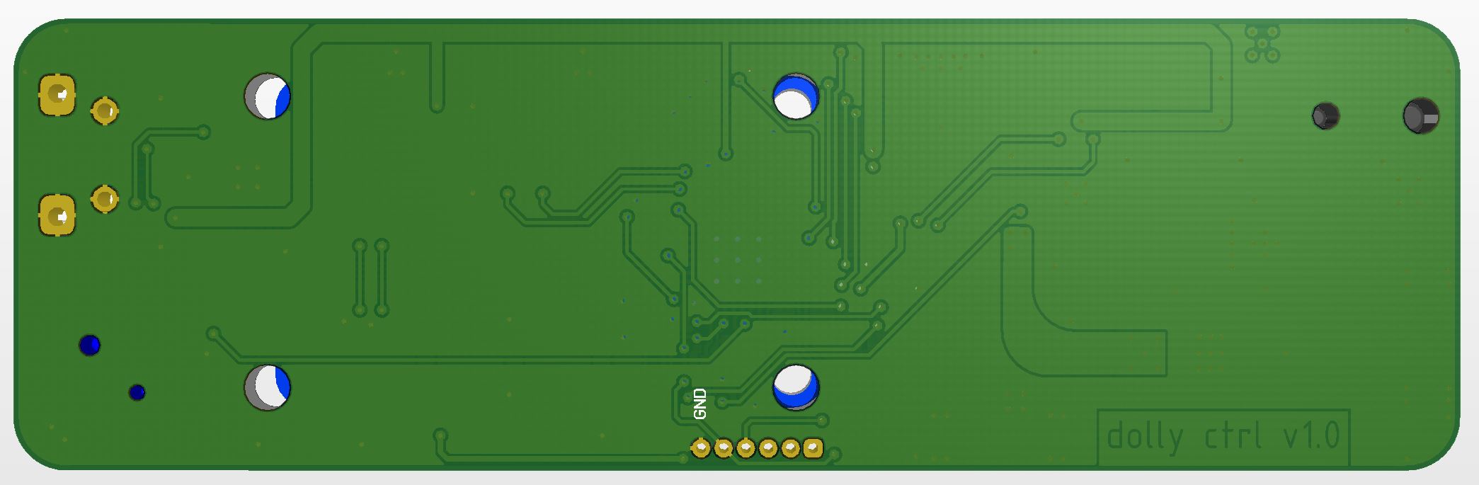
As mentioned before, I made a double-sided PCB with all components on the top layer. The routing was a bit difficult as there is a size limitation and I had to mount and connect several connectors and the OLED also. But everything went well. :)
The red color is the top-copper, blue is the bottom-copper. Green shows the top silkscreen. The whole PCB has a poured ground layer on the top and bottom layer.

17
Renderings
As CircuitStudio offers the option to include 3D-models for the parts, I used this to generate some really nice renderings.
Top Layer

Bottom Layer
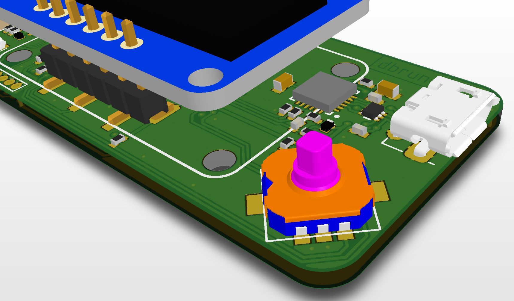
Navigation Stick and CP2104 USB-to-UART bridge
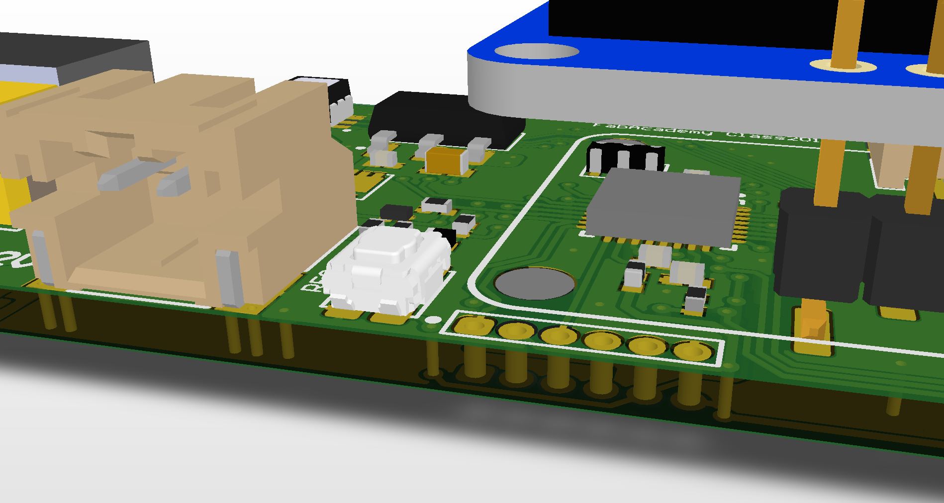
ISP header, reset button and the ATMega328P
18
PCB production
For the PCB production I chose the Seeed Fusion service, which provides a cost-effective and fast PCB service. This allows using much smaller Vias than using our rivet press from Bungard, a good soldermask which allows using smaller parts and reduces the chance of shorted circuits.
As Hackaday mentioned with the "Why are you still making PCBs?" back in 2015, I also decided a long time ago to use PCB services to produce my PCBs. I can't count how many self-milled PCBs had a strange behaviour or esoterical faults, which resulted in time-consuming debugging. The process to mill a PCB is fast, yes. This is - in my humble opinion - the the only reason for this. If there are two weeks left, buy them somewhere online.
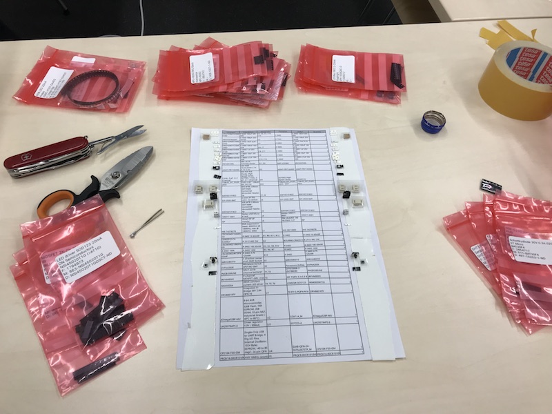
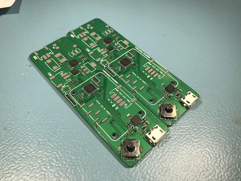
The PCBs arrived ~2 weeks after ordering them. While waiting for the PCBs, I ordered the parts at Mouser. To simplify the assembly, I printed the BOM and used double-sided tape to sort the parts.
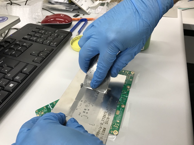
The second step is to apply the solderpaste to the PCB. Align the stecil (ordered with the PCBs at Seeed), apply solderpaste on the stencil and coat it with a spatula.
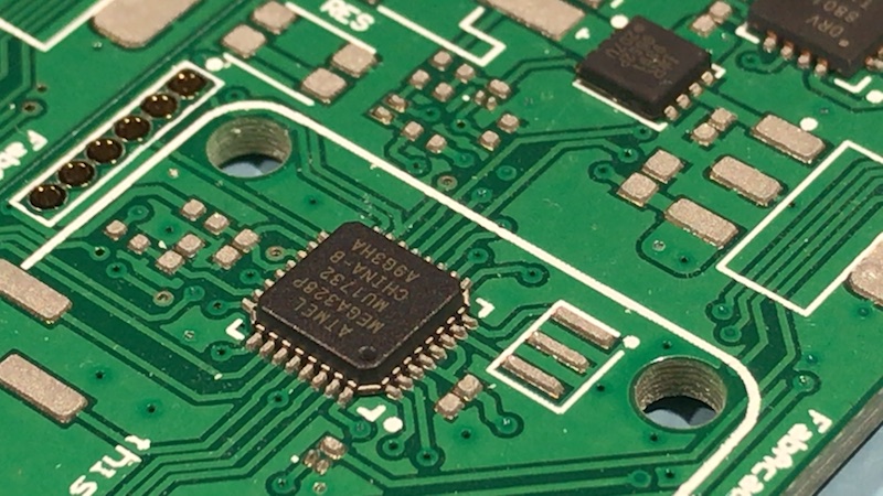
While placing parts. Starting with the most annoying parts like ATMega, DRV8801 and CP2104 is recommend.
The ATMega328p-MU - and a lot of solderpaste. All parts were placed by hand!
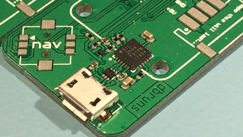
The CP2104 with USB port and TVS-Diode.
After placing all parts, the PCB went into the dry-oven at 265°C for 2min45.
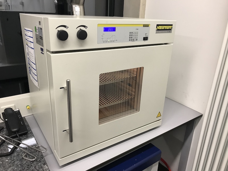
I soldered the display by hand after soldering all the SMT parts in the dry-oven.
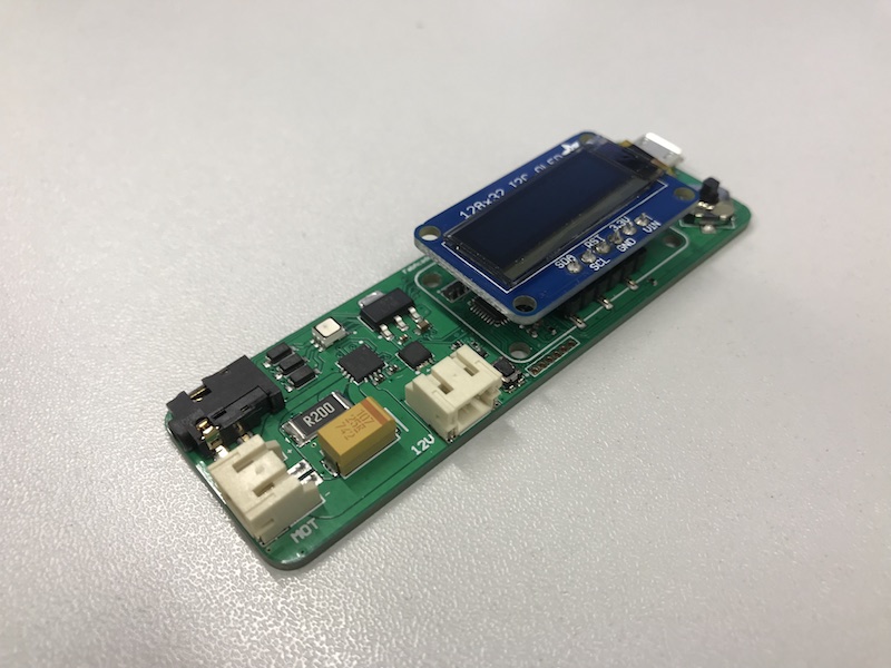
The PCBs are finished, now. I'll test them in the output/input week. All other coding for the final project will take place in the Software section.
19
Downloads

This work by Daniel Bruns is licensed under a Creative Commons Attribution-NonCommercial-ShareAlike 4.0 International License.