01
04
10
11
This is the assembly part of my final project. In this part I'll show you how to fit all these parts together, without burning down the Lab.
12
Mechanical assembly
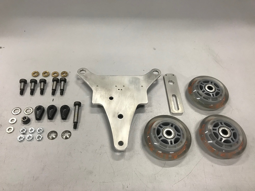
Mechanical BOM
1 37D Gearmotor /w 64CPR encoder (the 600:1 Gearbox was in stock before)
2 BH-341-1P battery tray 4x AA
3 ISO 7379 M6x16 shoulder screws
2 ISO 7379 M6x20 shoulder screws
1 ISO 7379 M6x35 shoulder screw
1 DIN 6331 M6 hexagon nut with collary
2 DIN 6319 8.4mm spherical washer
6 608 bearings /w ceramic balls
2 M2.5x10 Screws
4 8mm collared bushing sintered bronze
4 M6 type B nuts
Some washers
This is the whole puzzle which I planned. Let's have a look if it works...
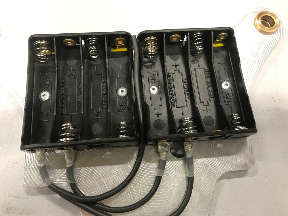
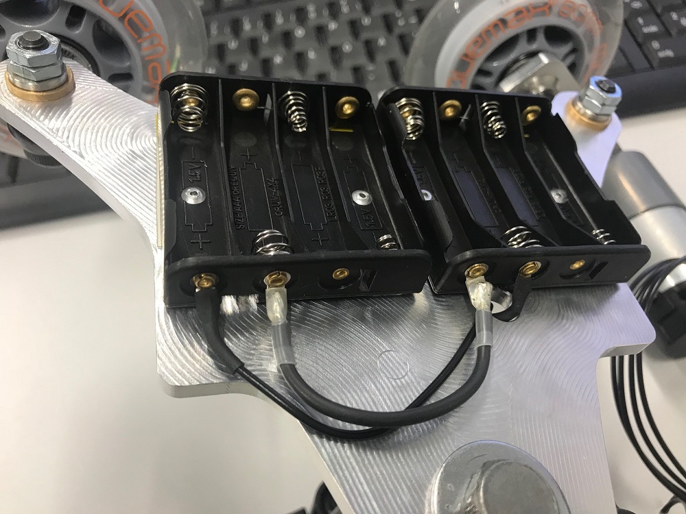
The first step was to mount the battery trays with rivets. I isolated the trays with Kapton tape, as I had a really really bad experience with such trays, a long time ago. Yes, normal batteries will get really hot when they're shorted.
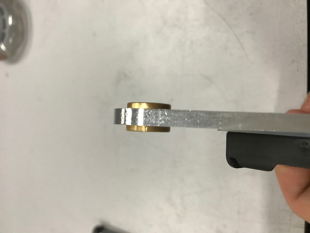
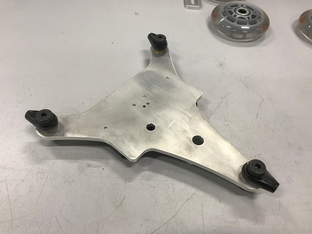
The second step was to mount the collared bushes into the main frame. With a little pressure they fit like a charm into the milled holes.
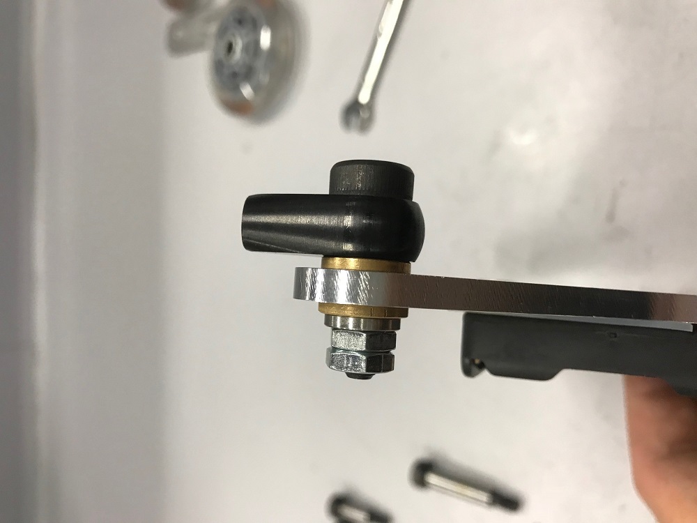
I installed the first axle mount. The swing nuts were the right decision as mount, as they only press on the inner ring of the bearing, without blocking the bearing. It was a long way until I found this solution. The bronze bushings are for smooth turning. The good thing: they are hard enough to set the proper angle for the wheels without getting loose too much like plastic bushings.
All axle mounts mounted with M6x16 shoulder screws :)
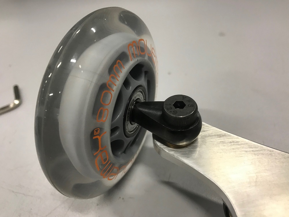
The wheels are secured with M6x20 shoulder screws. They have the right diameter on a shaft and not a thread, where the bearings are. This leads to a much stiffer construction, as the screws don't have to be tighten this much to secure the wheels without any jiggle.
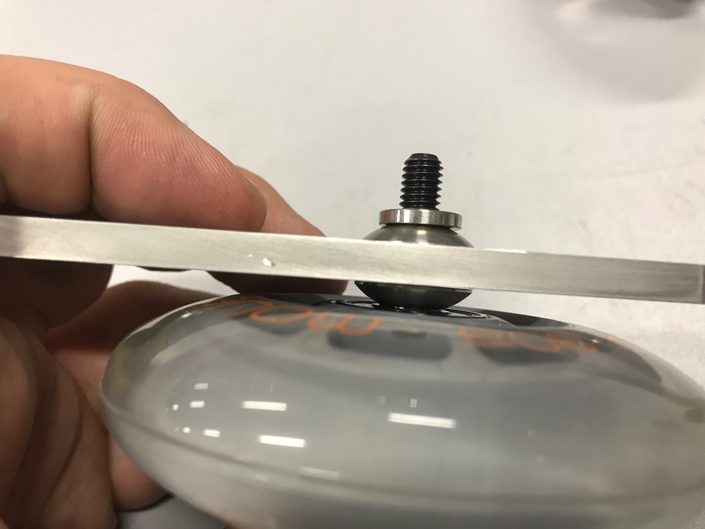
The wheel pod where the motor will be mounted, must be secured with a M6x35 shoulder screw and 2 spherical washers, as the lever must be even hold in place, without jiggling around.
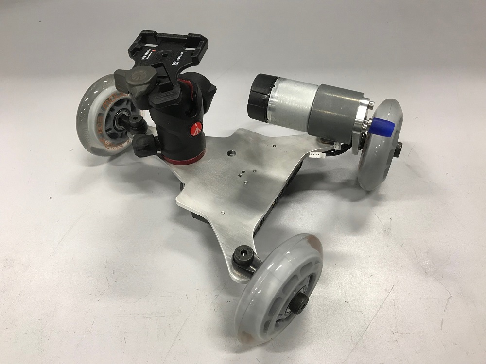
The main frame with all mounted axle mounts and wheels. Nice and stiff :)
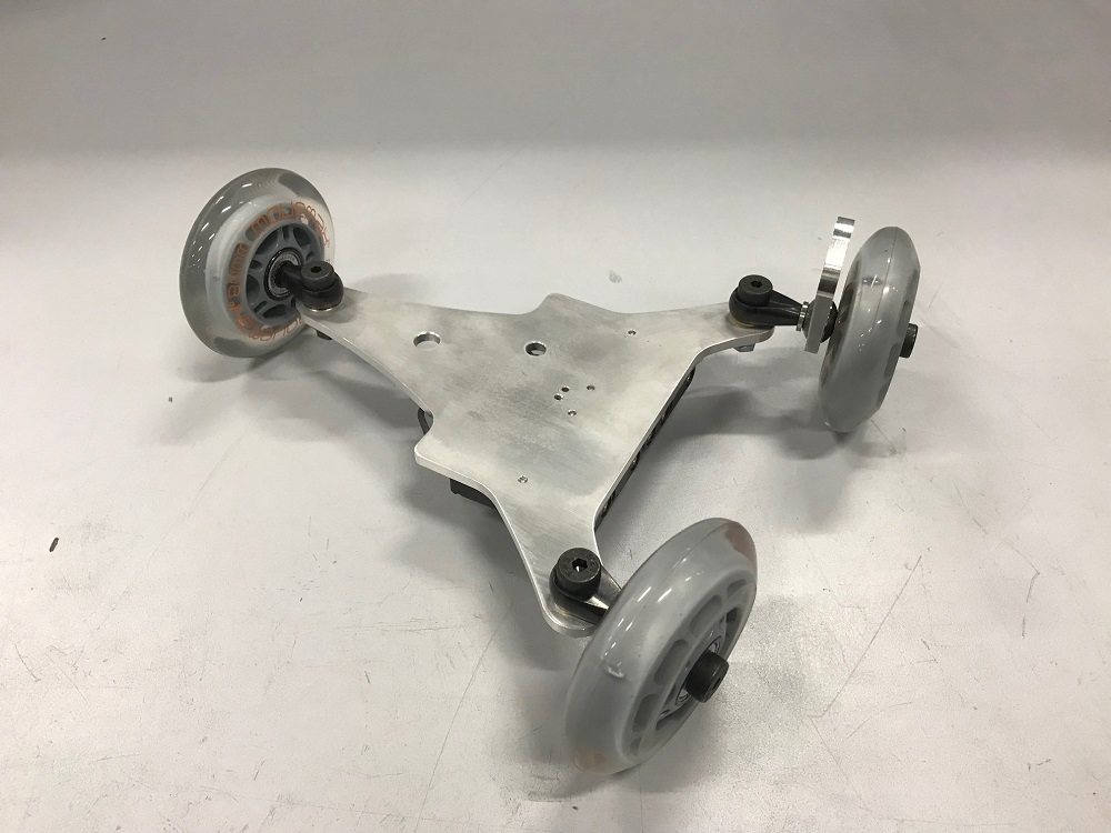
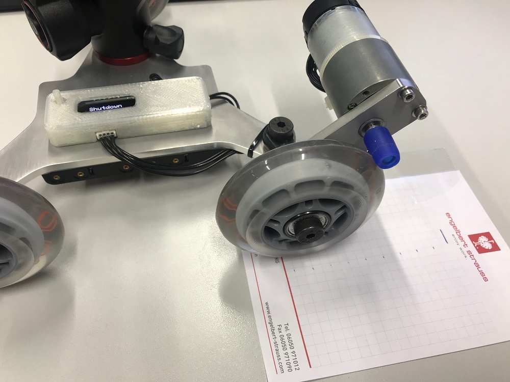
The mainframe with mounted motor and ball head for the camera. The next will be mounting the electronics on the frame.
13
Electrical assembly
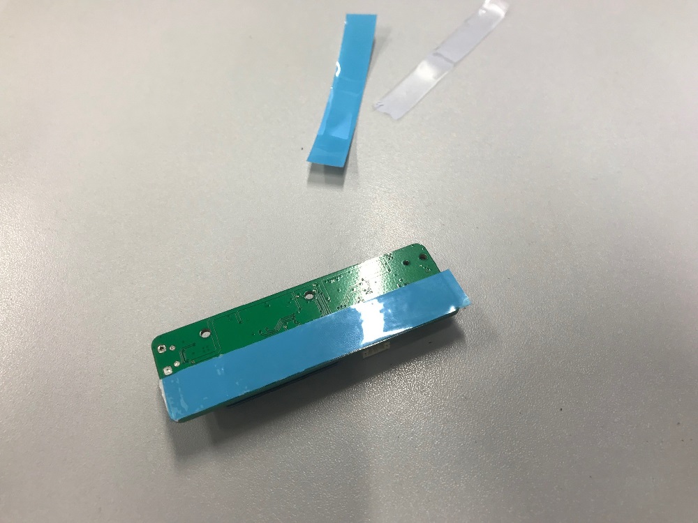
The main electrical assembly was to assemble the PCB with the connectors. The only thing I had to do beside the PCB: soldering two cables to the battery tray and securing the PCB with heat conducting double-sided tape to the main frame. The first step was to solder the trays and the power cable to the PCB.
The next step was to secure the PCB with the double-sided tape to the main frame. I had some old 3M heat conducting tape for heatsinks, which helps to dissipate heat from the PCB (especially the voltage regulator) to the aluminium mainframe.
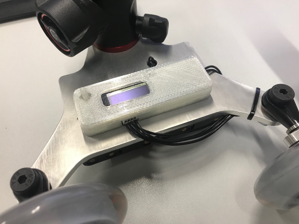
This is the PCB after placing it to the mainframe.
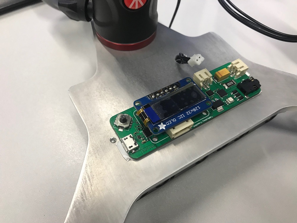
The finished enclosure is mounted with the overlap of the double-sided heat conducting tape, which secures the PCB on the main frame.
14
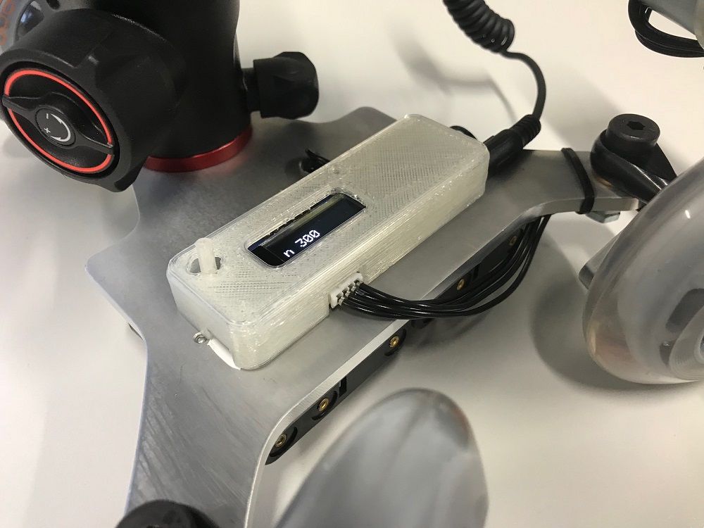
First Startup
No historical moment, but nothing burnt smoked also.
15
Disemprove tweaking around...
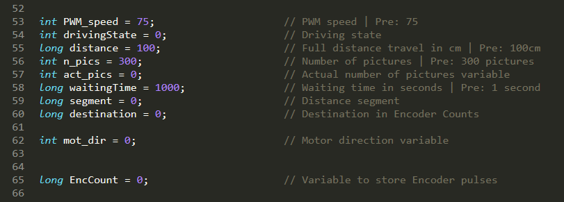
One of my first steps I made after the first real-startup was to change the variables for the number of pictures and movement distance to "real world" values. The actual settings with 300 pictures and 100 cm travel distance are realistic.
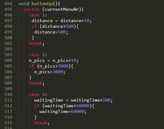
I changed the steps to increase or decrease the values for the different settings in the menu also. It's not feasible to change the number of the pictures or travel distance by 1. The actual setting is +10 and -10.
The last but most import step was to calibrate the movement of the skater to achieve an accurate movement, without dropping the camera into the water or snow.
The encoder has 64CPR - this means: 64 counts per revolution, the silicon tube over the motoraxle has 11 mm outer diameter.
11 mm * pi = 34,6 mm -> 38400 counts per revolution - this results in 11100 counts per 1 cm (38400/3,46). As only 1/2 of the steps is the real signal, because the other half is just for the direction detection, the needed value is 5550.
I achieved nearly the 100 mm, when set to 100 mm. Different surfaces and different pressures on the roll result in different slip and a different movement. But every test resulted in a range of 0.5 mm to 2 mm difference. That's fairly ok for this machine. Measuring with a caliper and angle has it's limits, too.
This is the menu structure after tweaking aroung a bit. Not bright and shiny but functional. :)
One of the first tests on the floor :)

This work by Daniel Bruns is licensed under a Creative Commons Attribution-NonCommercial-ShareAlike 4.0 International License.