Embedded programming
This week's assignment is to Read a microcontroller data sheet. Program the board to do something, with as many different programming languages and programming environments as possible.
- Datasheet
- Programming my board
- group project: performance and development workflows for other architectures
reading a datasheet
To be able to design the circuit in week 6, I had to check the datasheet of the microcontroller a lot anyway
I've used the data sheet when creating the PCB to check out the pinout to determine where I can and cannot connect my button and LED.
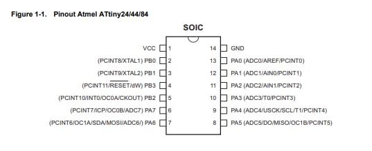
you'll notice that some pins are labeled PA and some are labeled PB, Using the datasheet to check for the differance I learned that PA stands for port A and PB stands for port B. both are bi-directional I/O. port A is 8bit and port B is 4 bit.
Why 20MHz ? why not go higher?
first we need to undrestand why it is used, the crystal forms oscillation, we need that to help us with time issues. the crystal can make 20 million cycles per second which helps the microcontroller calculate time. we can use the internal 1MHZ or 8 MHz oscillator but that would limit out speed.
well then that brings us to why we cant go higher. if a bigger number means better preformance can we just swap it for a 32MHz crystal? The datasheet answers that and the answer is no.
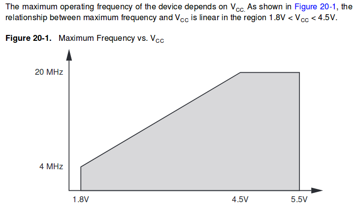
The datasheet shows that the highest frequency we can go is 20MHz, and even lower than that when we power the micrcontroller with lower voltage. technically the datasheet normally accounts for the worst case scenario so normally you can push the limits a bit if you are using the micrcontroller in moderate conditions and not in high tempretures for example (I've over clocked my micrcontrollers at 20MHz while powering them with 3.3V before and it worked fine) but its not a good idea to do that. datasheets do acount for the most extreme cases but thy are there for a reason and its not a good idea to not follow them.
Programming my board
Im using my board that I made on electronics design week assignment and my programmer that i made during electronics production week assignment . I have a programmer, I have a board, time to get programming.
I have already programmed my board to control the LED using the button (To be honest with this board there isnt much more that it can do) So lets try programming it and doing different things with it.
What questions do I have? What would I like to learn more about?
Whats with all those headers and how do I use them to program my board?
I have an ISP and an FTDI header on my board, each of those does different things and i couldnt seem to wrap my head around what they do exactly. I knew i used them to communicate with the board but thats about it.
ISP is an In-System-Programmer that is used to program AVR microcontrollers.ISP can be used to upload sketches directly on the microcontroller without the need of the bootloader.ISP does not provide power however so it needs to be supplied seperately, in this case through the other header.
FTDI does supply power, it allows serial communication with the board.
Whats a bootloader ?
The botloader is basically a little software that runs on the microcontroller and interacts with the programs it gets sent everytime it is reset or turned on to be programmed. It recieves new program information and writes that information to the program memory of the processor
Actually programming
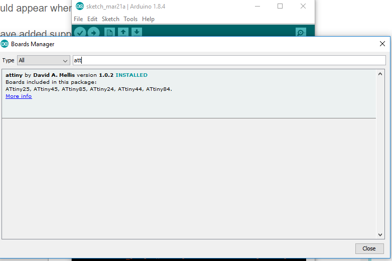
Okay so I programmed the board before to test it out. Now i am trying new things. I am programming it using my programmer and the arduino IDE. first there were steps to complete to do so. I had to add the attiny to the list of boards as the arduino IDE does not have it by default.
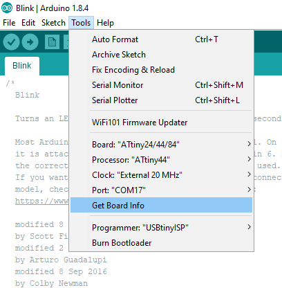
And i had to enter the boare information to program it, I am using a 20MHz and had to select the programmer
The first thing I wanted to check was the classic blink program, turns out that was a good thing to start with cause i set it up to be on for one second and off for one second, and it wasnt behaving right.
void setup() {
  // initialize digital pin LED_BUILTIN as an output.
  pinMode(PA3, OUTPUT);
}

// the loop function runs over and over again forever
void loop() {
  digitalWrite(PA3, HIGH);   // turn the LED on (HIGH is the voltage level)
  delay(1000);                       // wait for a second
  digitalWrite(PA3, LOW);    // turn the LED off by making the voltage LOW
  delay(1000);                       // wait for a second
}
My board was NOT turning on and off for a second, it was actually taking way longer than that, It took over 4 seconds on and four seconds off.
Upon some reaserch and testing, I found out that i could fix it and set up the timing right by selecting the "burn bootloader" option in the arduino IDE. there are more complicated ways to do this but this was the easiest way i found and it did work. There isnt a bootloader assosiated with the attiny, so basicallyu what doing that does is just set the timing right. doing that fixed it and it was turning on and off for a second
Okay so lets do something else, well what else can we do with a single led and a button, lets try some other stuff out
my led is on pin PA3 which is not PWM capable (I should have planned that better, maybe checking the datasheet thoroughly BEFORE making the board would have been a good idea) so a fade code was not an option. I tried it just to see what happens (dunno what i expected) and it was just turning on and off (obviously) becuase the signal was just togglibng on and off and there was no varaing pulse width modulated signal.
turning the led on and off with the button
I have done a code in the electronics design week assignment that turns the led off while the button is pressed, and keeps it on when it isnt, but how about using the button to turn it on and off without having to keep holding it down?
doing this is very easy, all i had to do was declare a variable for statuse of the led and change it every time the button is pressed to basically store the selection of having the led on or off
int buttonPin = PA2;
int ledPin = PA3;
int ledState = LOW;         // the current state of the output pin
int buttonState = LOW;             // the current reading from the input pin
int lastButtonState = HIGH;   // the previous reading from the input pin
int reading;

long lastDebounceTime = 0;  // the last time the output pin was toggled
long debounceDelay = 50;

void setup() {
  // declare pin 9 to be an output:
  pinMode(ledPin, OUTPUT);
  pinMode(buttonPin, INPUT);
}

void loop() {
  reading = digitalRead(buttonPin);
   if (reading != lastButtonState) {
      lastDebounceTime = millis();
      lastButtonState = reading;
   }

   if ((millis() - lastDebounceTime) > debounceDelay) {
       if (buttonState != lastButtonState) {
           buttonState = lastButtonState;
           if (buttonState == HIGH) {
                 ledState = !ledState;
                 digitalWrite(ledPin, ledState);
           }
       }
   }
}
Testing different programming environments
I decided to use different micrcontrollers to test out as many enviornments as possible.
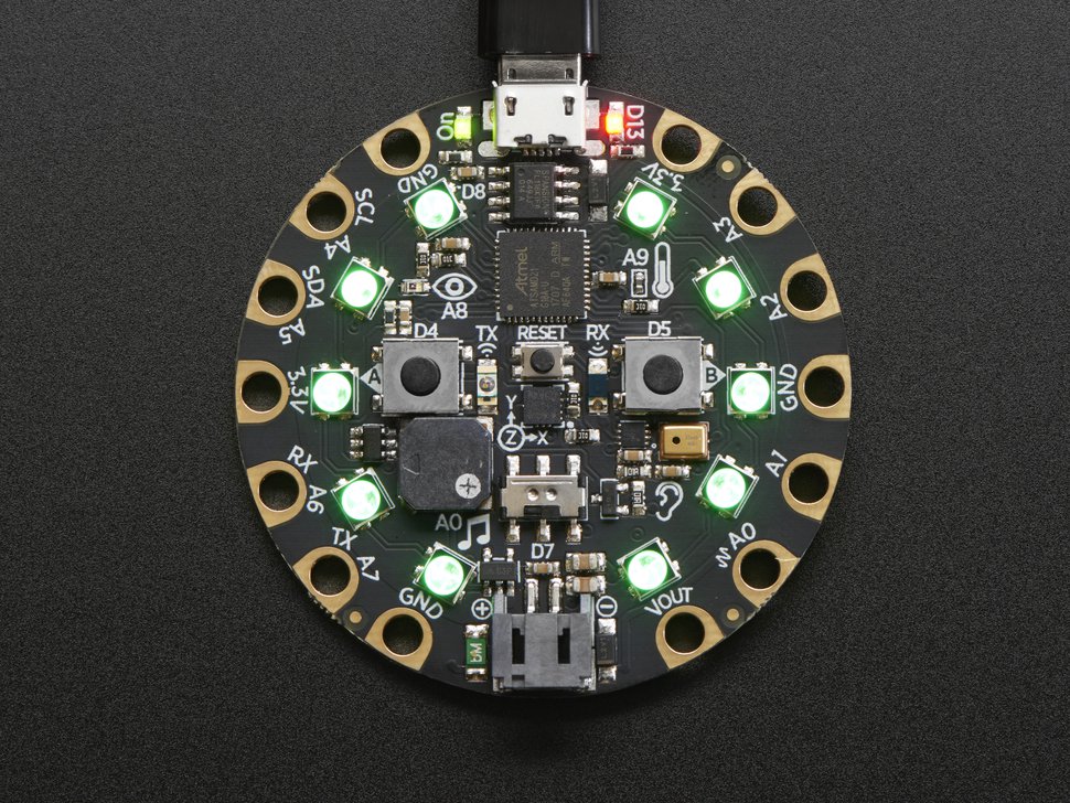
I had a microcontroller called Adafruit Circuit Playground Express which is a small lightweight microcontroller board that can be priogrammed using several methods. i thoght it was interesting as it allows you to use different methods at once and contained several built in sensors and input devices.
It contains a light sensor that detects when it goes dark and can detect sounds such as loud noises, an accelerometer and two buttons for input.
It also contains several LEDs and a speaker for output. it runs on ATSAMD21 ARM Cortex microchip.
The interesting part is that it is easy to program using several enviornments. through the ada fruit website web based programming
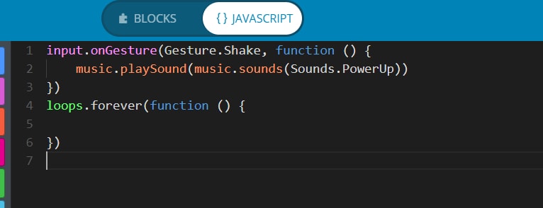
The was a graphical block based enviornment which was quite neat and easy to use. i liked it but thought it was probably great for begginers but for serious programming abilities and to create a complex program it would get too complicated and contain way too many blocks to the point whre it gets complicated. I've used visual programming enviornments before and prefer text based ones as they are easier to debug in my opinion.
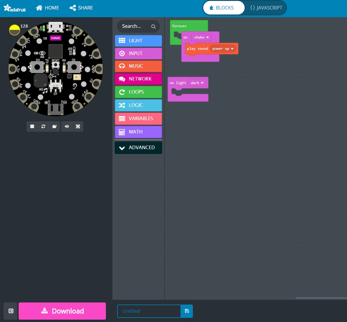
The program in the image above plays a sound when the micrcontroller is being shaken.
It also contains a javascript based programming. the following code achives the same function:
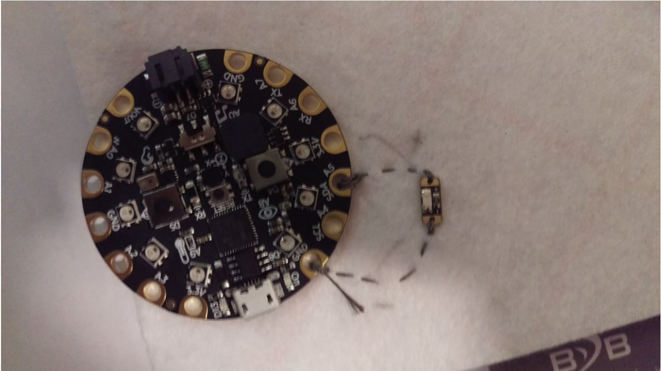
Along with the experimental things Ive done this week. I decided to try some conductive thread available at the lab to test out using a micrcontroller on textile. I've tried it with an LED on a pieace of fabric. It was pretty neat seeing this work and Im really interested in exploring the capabilities of this further.
I thought it was so cool, that I may have gotten carried away. i am preparig for an interactive art workshop that i am delevering so i decided to use this assignment to experiment in this feild. the end result was pretty cool.
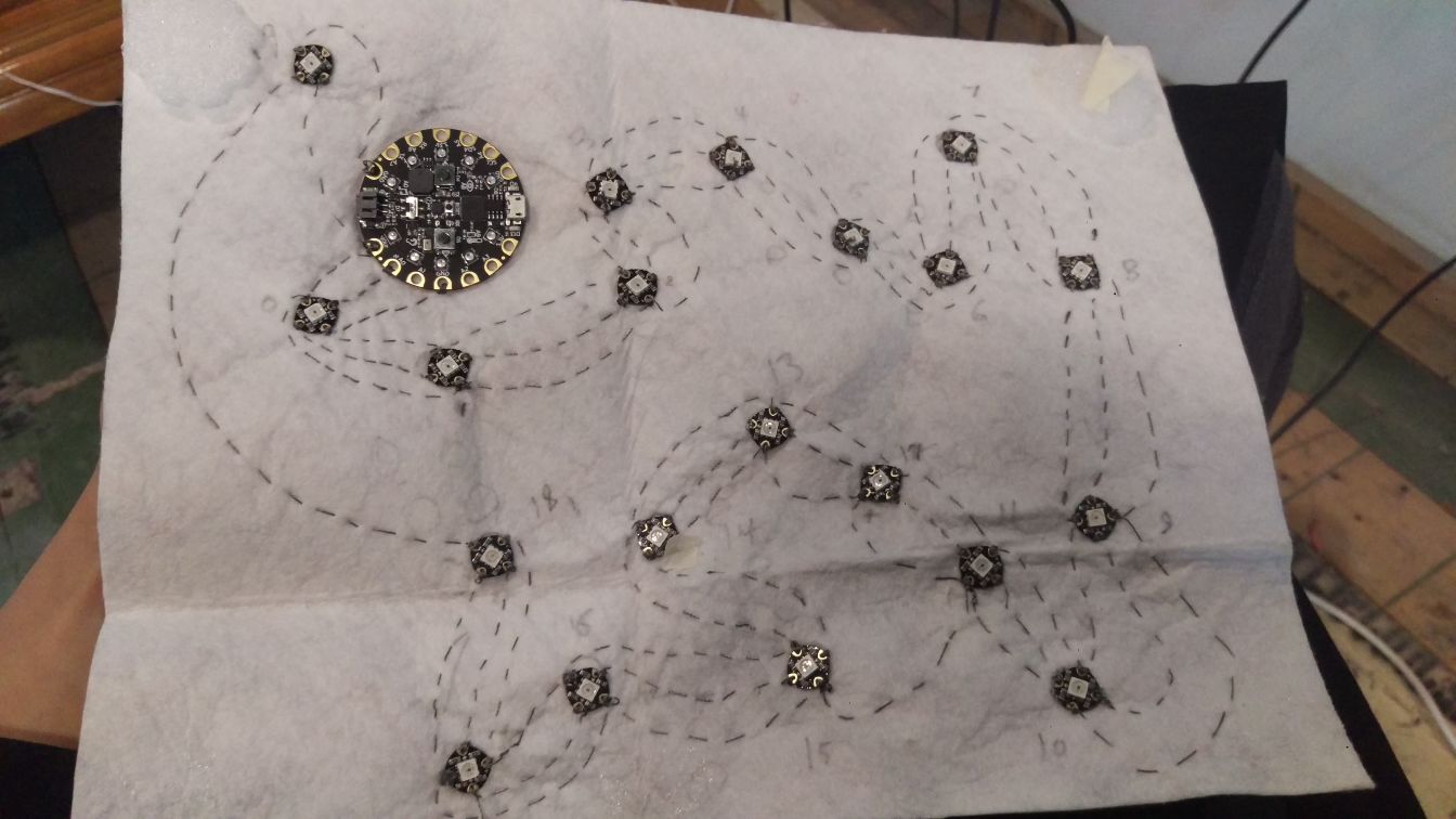

its an interactive art piece, that interacts with the user by lighting up the rgb leds (connected by inductive thread on fabric) different colors depending on the movment.