Electronics production
This week's assignment is to make an in-circuit programmer by milling the programer PCB, soldering on the components and getting started on programming it
Group project: Characterize the specifications of your PCB production process.
individual project: Make an in-circuit programmer by milling the PCB, then optionally, trying other processes.
Group Project: Characterize the specifications of the PCB production process
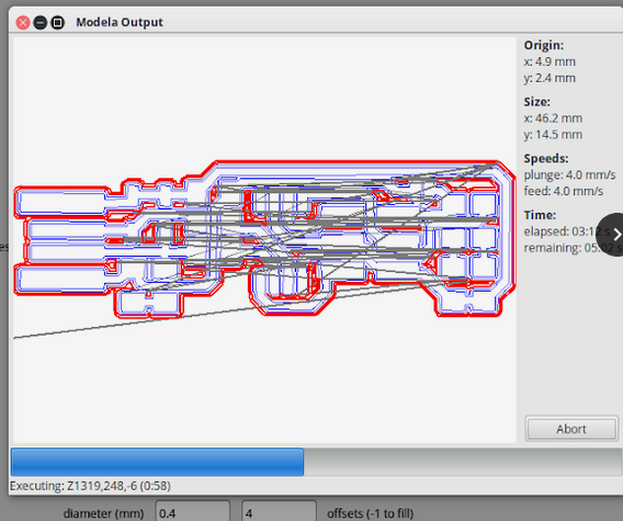
The milling machine used is a Roland Mdx15 Milling Machine and the program used to mill is fabmodules.
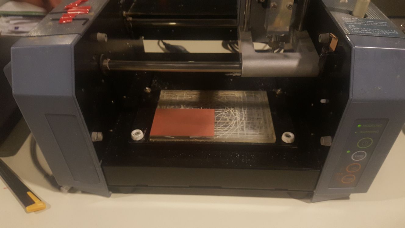
To be able to cut there are important things to consider, including what type and size of drill to use, the zeroing of the machines when cutting and the cutting parameters.
To test the machine we first made a test mill with different track sizes, we did the mill twice with an old drill tool and a new one we just opened from the packaging.
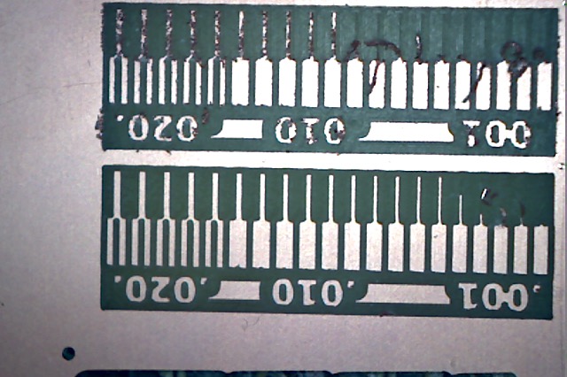
both drill bits are 1/32 inch. As you can tell from the image, the old bit was very dull and actually turned out to be broken, the mill made using a brand new drill bit was a lot smoother, however it still did not manage to cut all the tracks and had limitations when reaching the smaller tracks. This information is useful for electronics design to know how large to keep our tracks when designing a pcb so it gets cut proparly. We concluded that 0.01 of an inch (the middle tracks in the test pcb) was a good track value.
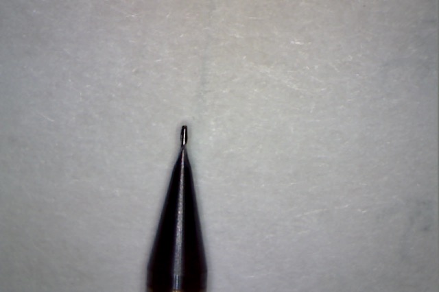 new
new
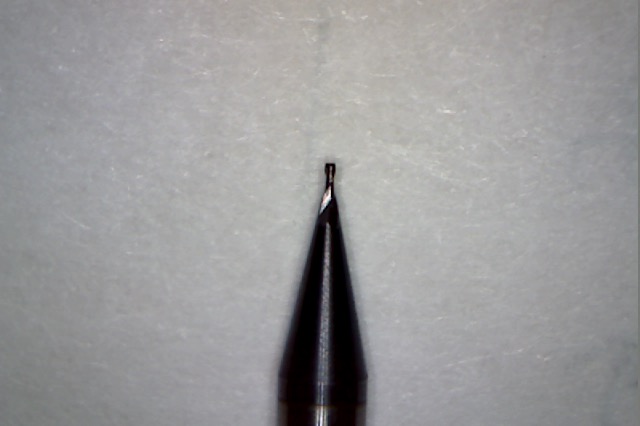 broken
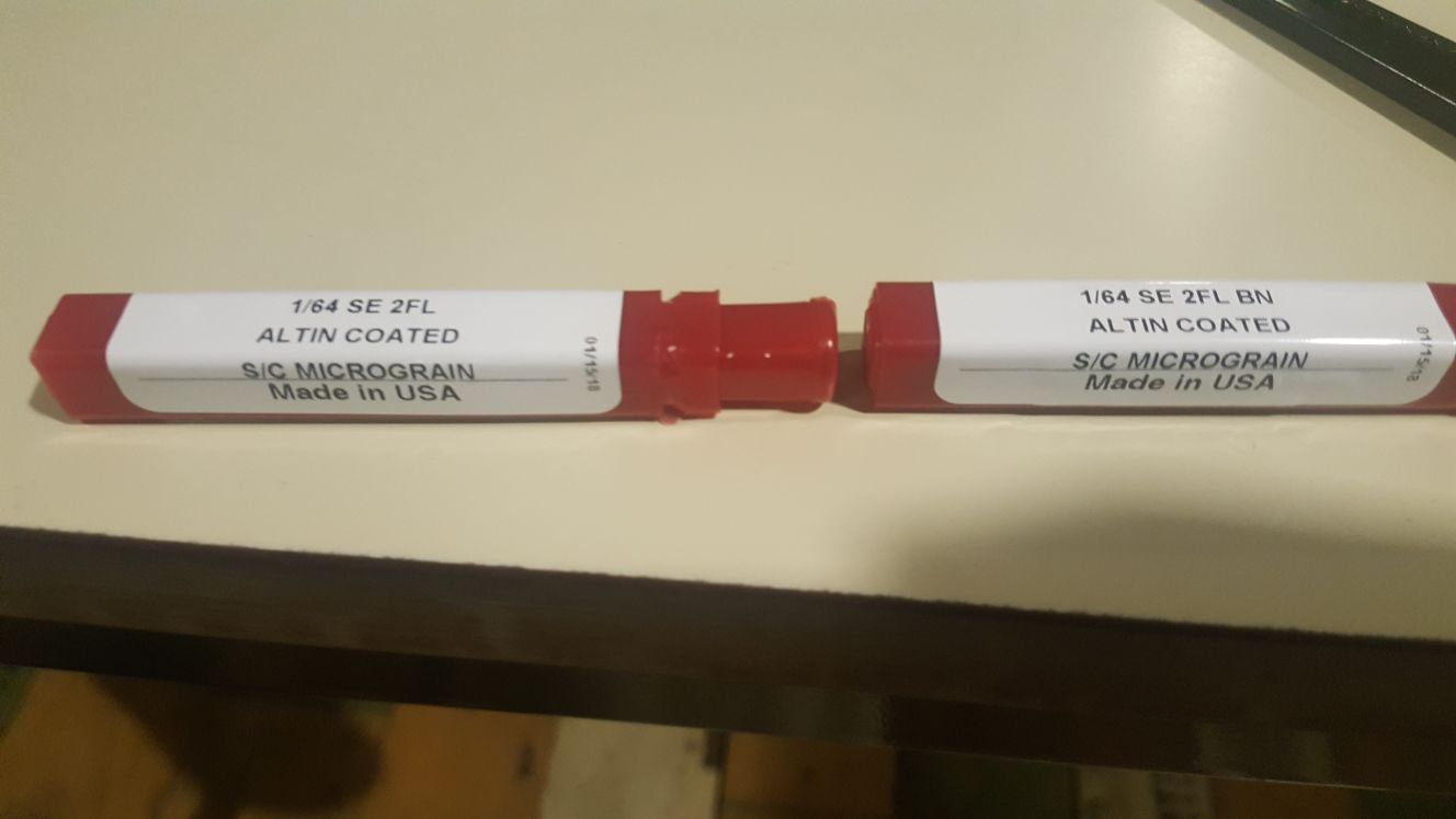
The size of the drill typically used is 1/64 inch for inner tracks and 1/32 inch for the boarders.
As for the type of drill bit, there are different types. there are ball tip types and flat tip. additionally there is a different number of flutes for every bit.

Next was zeroing the machine. The pcb is stuck using a double sided tape and the zeroing is done manually by moving the x and y axis to the edge of the pcb.
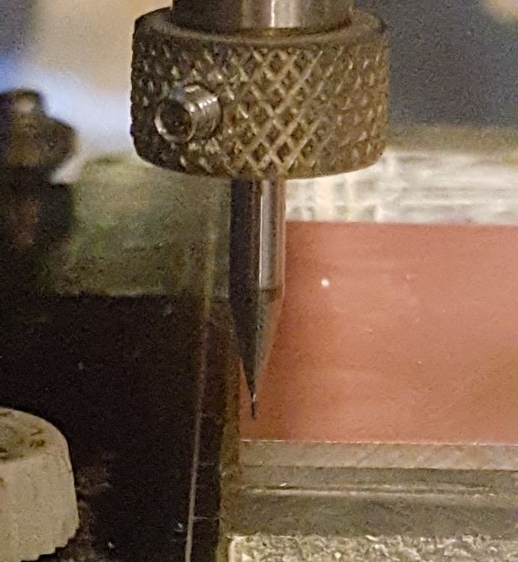
the tip is then lowered to the pcb and that is how th z axis is zeroed. We moved the x and y axis to the zero position on fabmodules.
The fnal part of the pcb production process specifications is the parameters set when cutting.
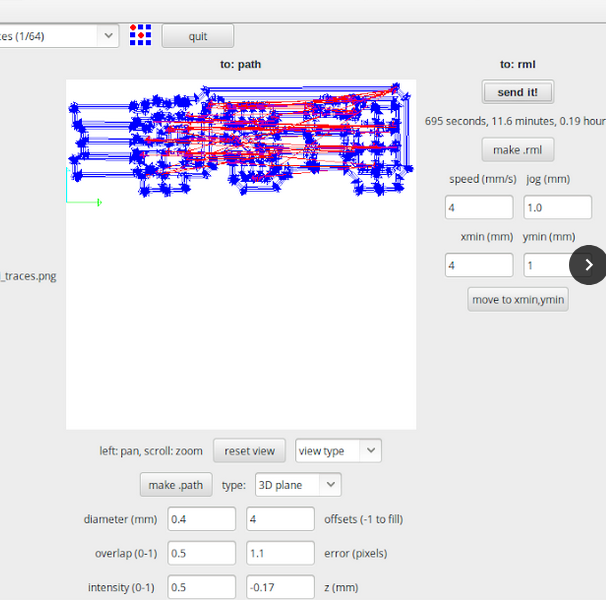
the parameters were set in fabmodules as it is the program used to complete the milling process.
The bit size was selected to be 1/64 inch
diameter 0.4 mm
offset 4
overlap 0.5
error (pixel) 1.1
intensity 0.5
Z mm -0.14

Milling the PCB
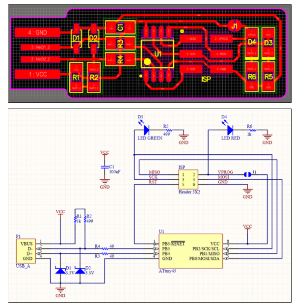
I first started by conducting a quick search on the different types of microcontrollers and the diffeent PCB designs through the FabAcademy archives. I decided to use Brian's PCB design
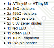
I started by making sure all the components needed for the circuit were avilable. I will be using two LEDs of the same color rather than the ones mentioned in the component list due to not having any on hand
I used fabmodules to do cutting on the milling machine. The milling machine used is a Roland Mdx15 Milling Machine. The mill bit used was a two flute double end mil bit which allowes for more chip space and easier chip removal
The cutting material was fixed on the machine for milling using double sided tape so it remains in place during the cutting process. Next, the milling bit had to be zeroed to make sure the cut was accurate. the possition settings were changed until the tip of the dril bit was touching the edge of the cutting material. The bit's position was then changed to the far end of the board to insure it was level before commencing the milling processs.
Soldering the PCB
I've soldered through hole components before but never SMD components. I assumed it would be really hard due to their very small sizes.
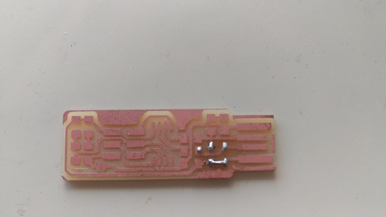
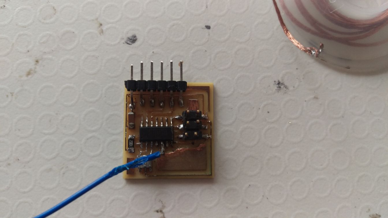
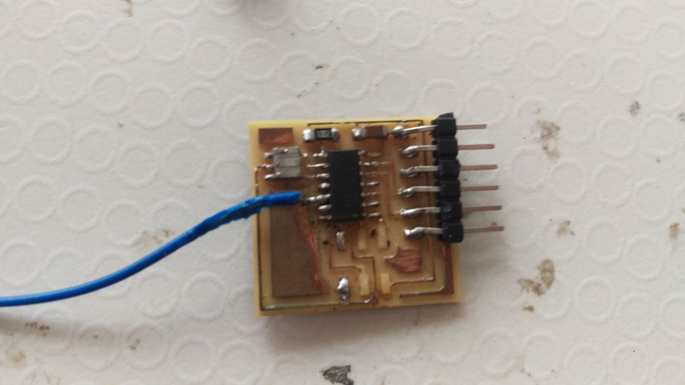
I didnt take a picture of the pcb until days later and by then it looked like this ( and was accidentaly almost mistook for someone elses PCB, hence the solder marks )
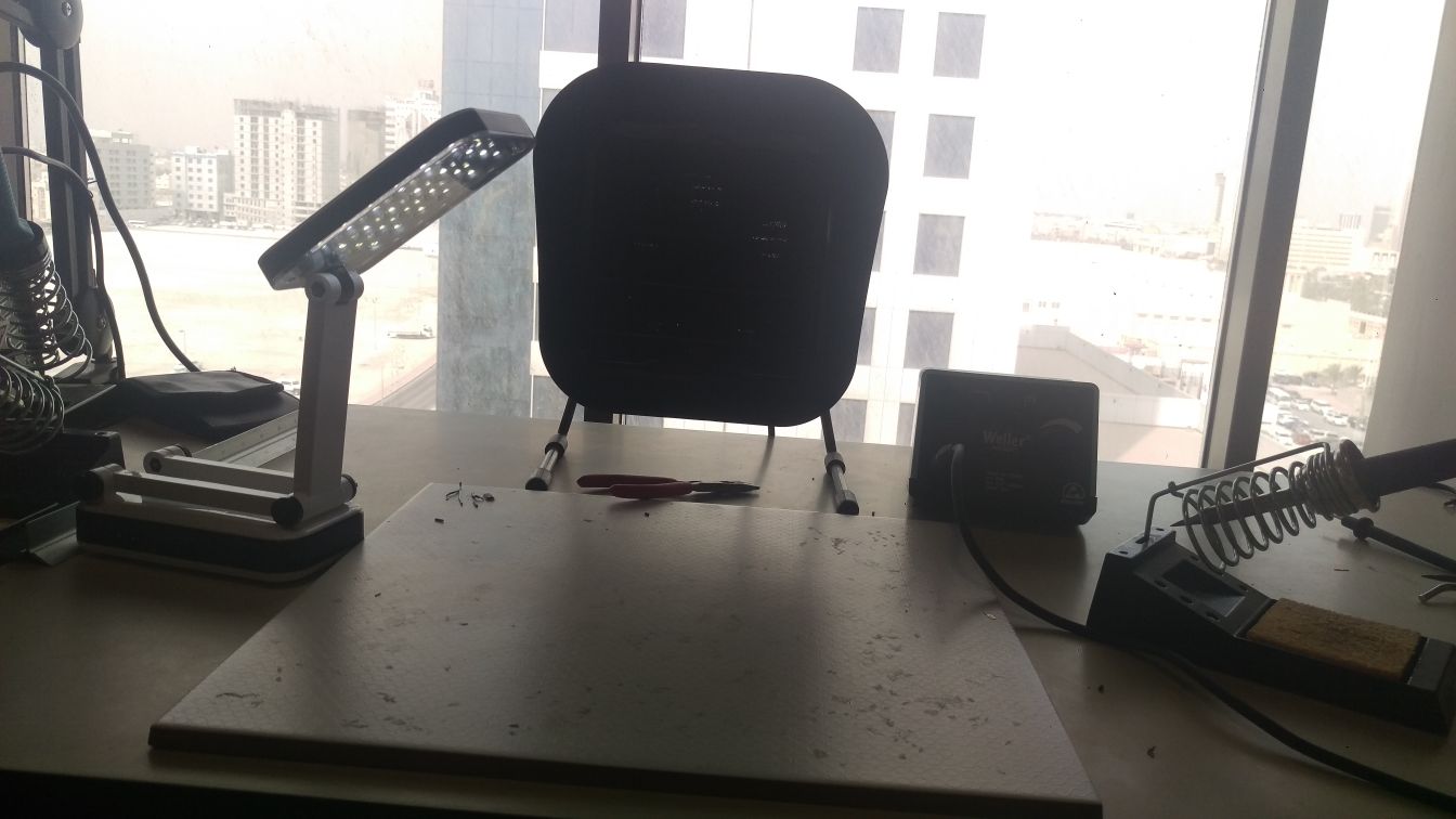
I started by setting up my soldering area to start working. The solder I was using was Lead based so using a solder fume extractor fan was essential.
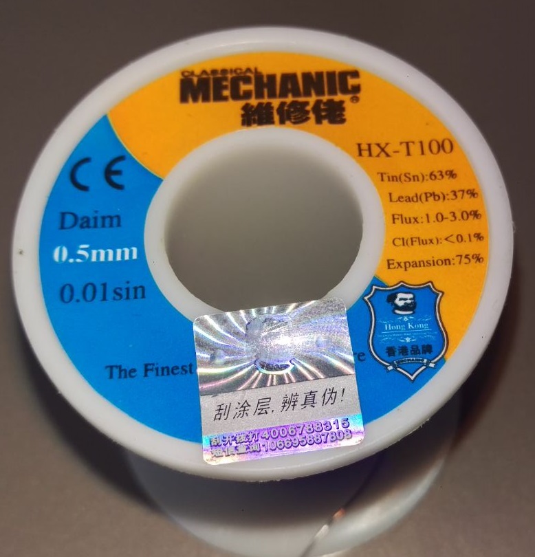
The solder wire contained a desent amount of flux and I thought the size (0.5 mm ) was ideal for soldering SMD components
I used Brian's PCB and schematic images as a guide to solder my components
I visually checked the connetions making sure there are no solder bridges as I went along. Instead of using a new header to put on, I decided to reuse one from an old scrap circuit that was laying around in the lab. To do that i had to desolder the header off of it. I used a solder braid for that task
The solder braid goes on the solder and is then I heated it with the tip of a hot soldering iron. the solder comes off into the braid
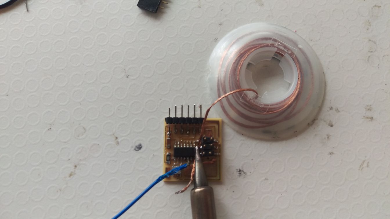
I think I pulled it off the pcb before getting the solder completely off cause some of the tracks came off too
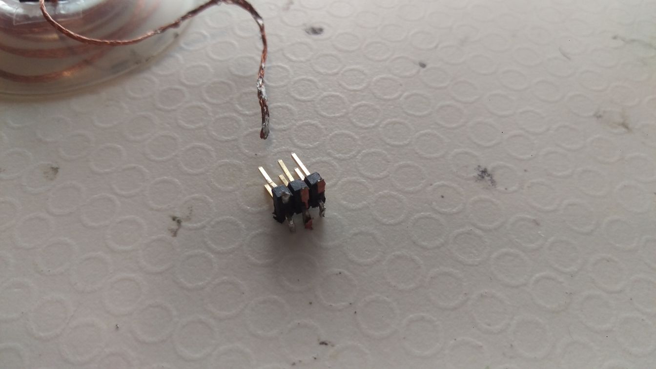
but the task was done. I cleaned off the leftover solder (and tracks) off the pins with the soldering iron and just used it
I removed the bit at the usb tip
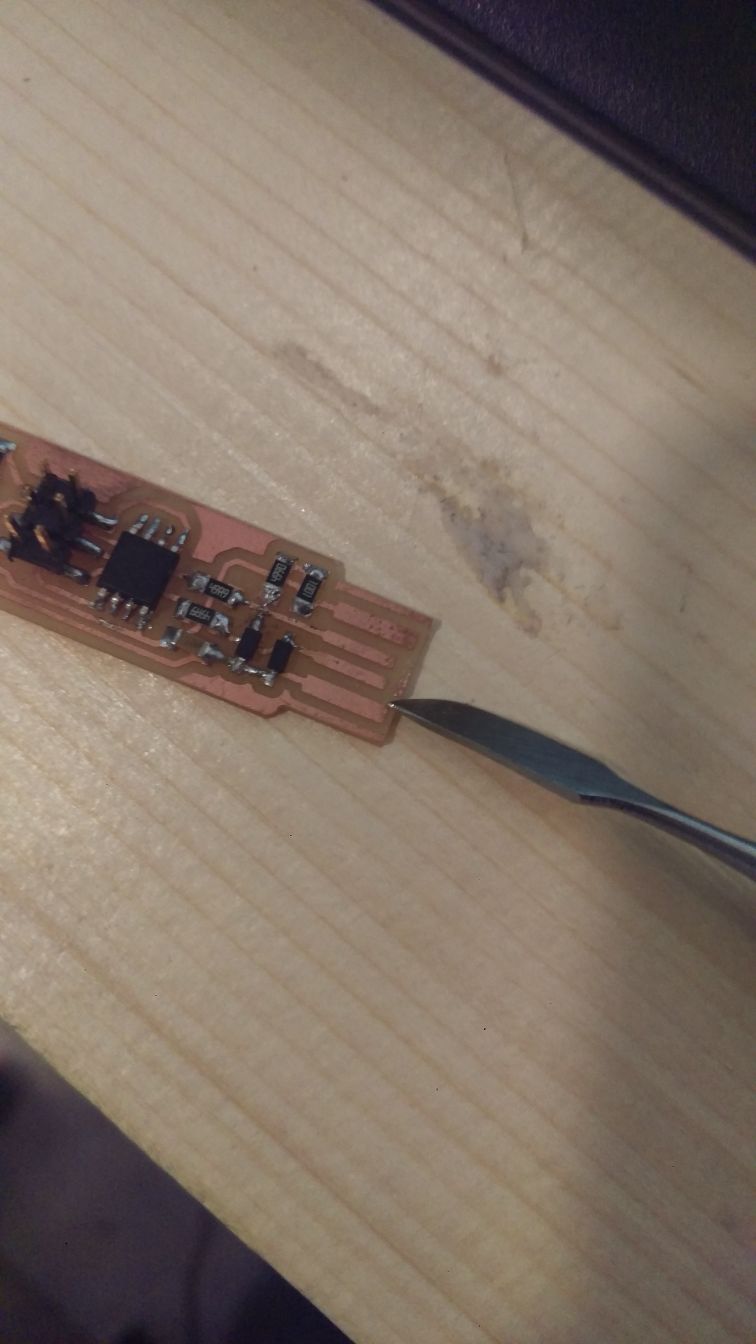
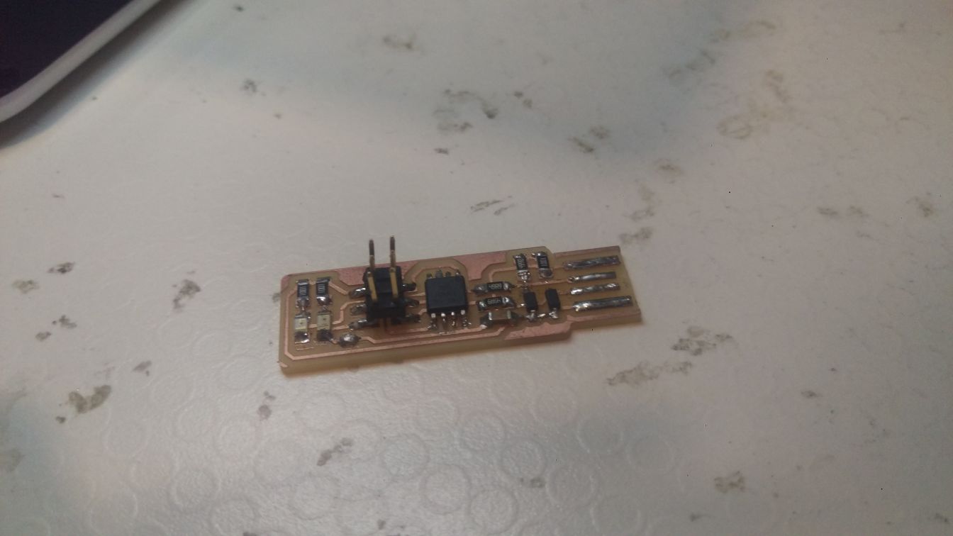
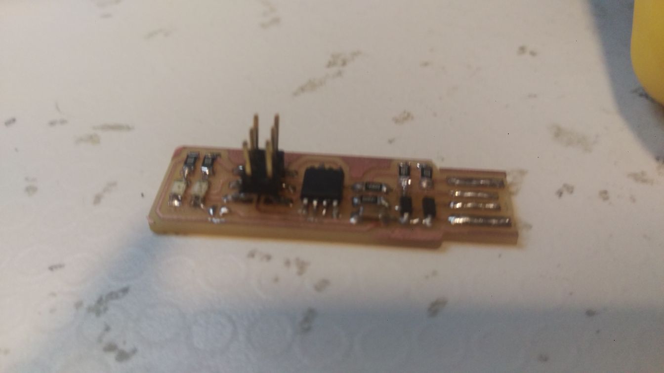
and with that I had a finished PCB
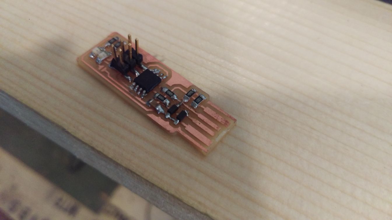
not too bad for my first SMD attempt. it went much better than expected.
Now it was testing and programming time
Programming
following brian instructions I downloaded crosspack for AVR and its firmware
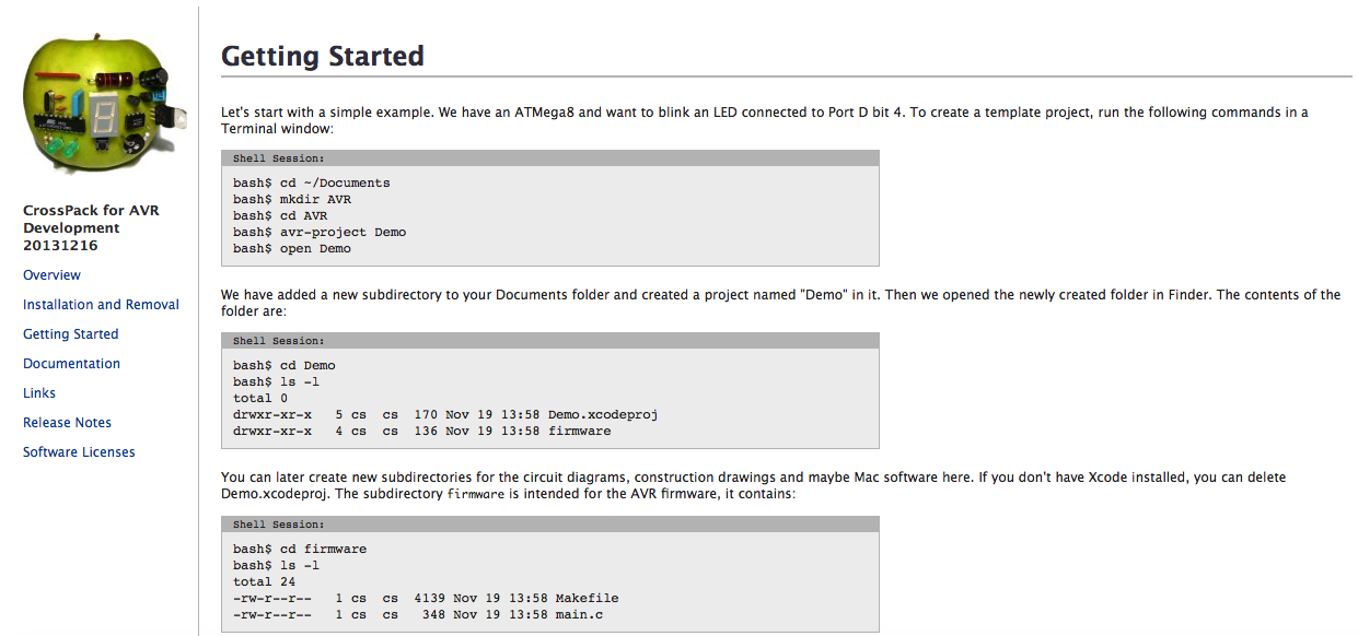
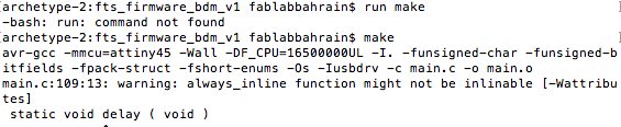
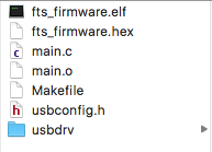
used the command make to create a hex file and make file
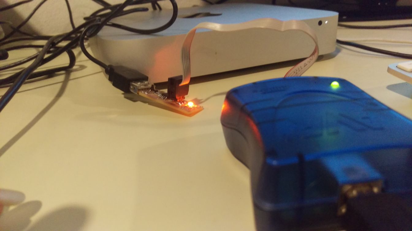
plugged in my programmer and my circuit
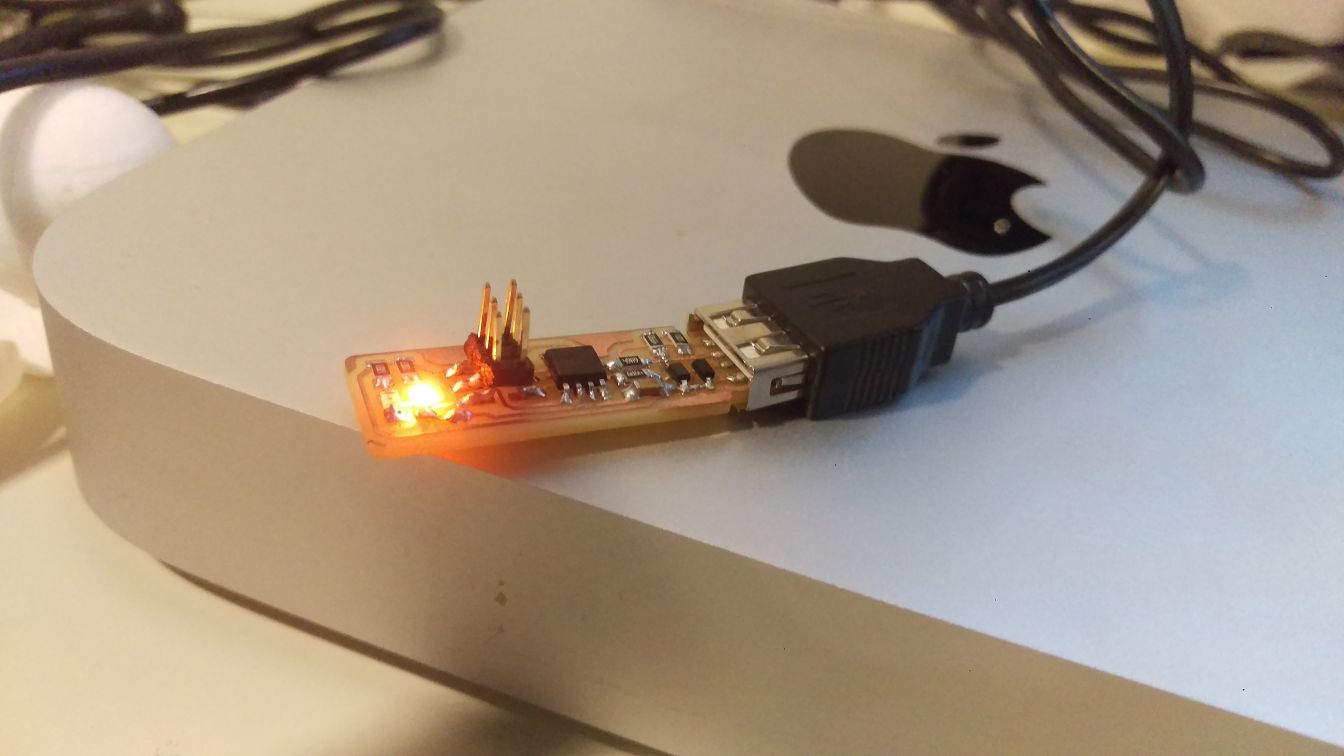
ITS ALIVE
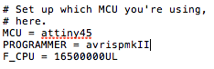
hanged the programmer to the programmer i am using in the makefile. the programmer i am using is avrispmkII
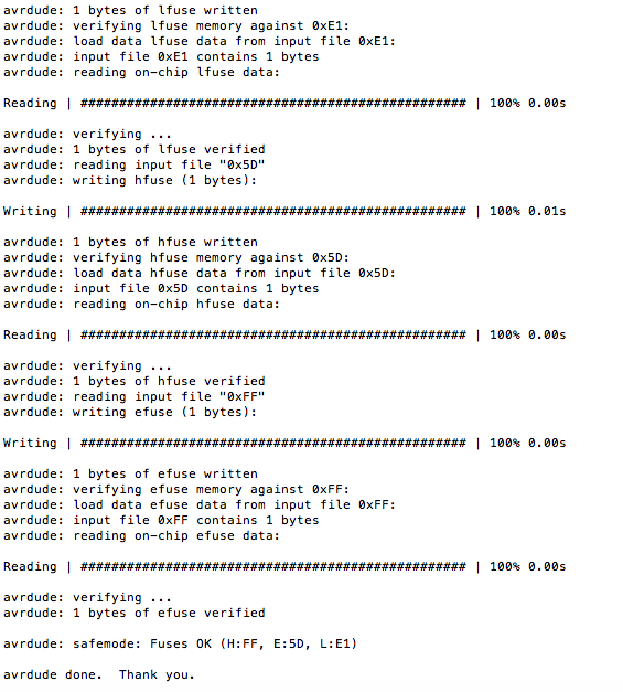
ran the command make flash
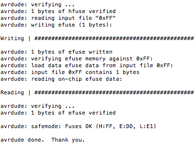
ran the commond make fuses
I unplugged my board
then unplugged my programmer
plugged my board back to the usb
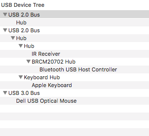
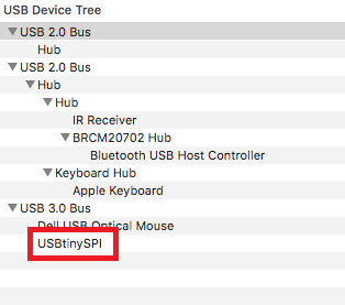
I checked if the usb ws recognized using two methods
about this mac > system report > usb
at first my device was not showing up with the device list
I followed Brian's debugging tips and tided up the soldering of the usb header
i plugged it back in and checked again , it was listed there this time
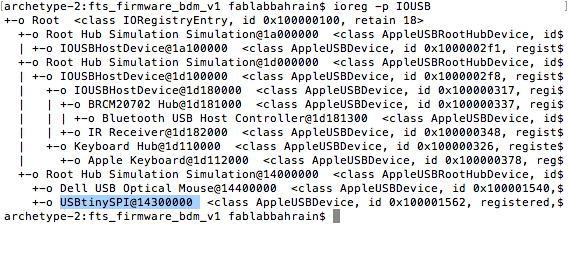
to double check i use the following command in the terminal
ioreg -p IOUSB
it appeared in the list too
after the it was time to blow the reset fuse
by doing this the attiny45 won't be reprogrammable in the future
i replugged my programmer and reconnected it to the board
i ran the command make rstdisbl
then it was time to desolder the solder bridge
i didn't need to use a desoldering braid. i just did it using a soldering iron tip.
[ before after pic]
i used a multimeter to insure i didn't have a connection anymore (continuity test)
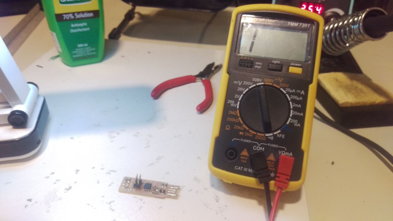
and with that, I had a working programmer ready to be used.