Week 15 - Networking and communications
Assignment
Design and build a wired and/or wireless network connecting at least two processors.
For this assignment i'm going to design and buil the asynchronous serial communication board
Making the boards
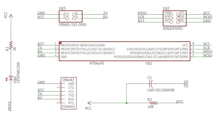
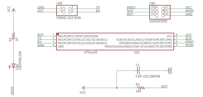
I designed the boards folowing Neil's design
Bridge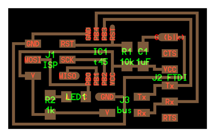
1X FTDI Header
1X Resistor (value 10k)
1X 6-Pin Programming Header
1X Microcontroller: attiny45
1X CAP 1uF
1 X 2X2 Pin Header SMD
1 X LED 1206 SMD
1 X 1k Resistor RES-US1206FAB
Bridge design result
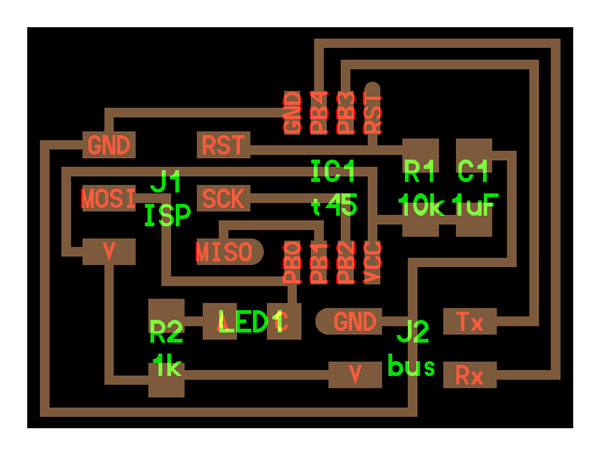
1X Resistor (value 10k)
1X 6-Pin Programming Header
1X Microcontroller: attiny45
1X CAP 1uF
1 X 2X2 Pin Header SMD
1 X LED 1206 SMD
1 X 1k Resistor RES-US1206FAB
Node design result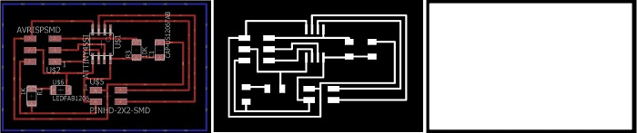
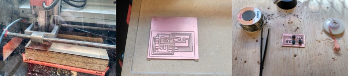
To know how to perform the milling and soldering check the information of the week 4 Electronic production
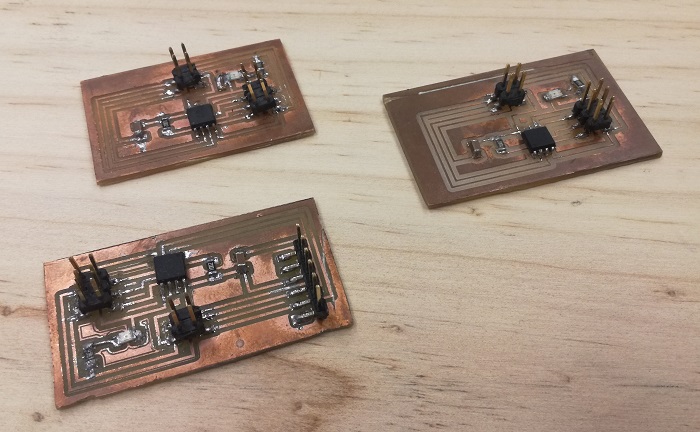
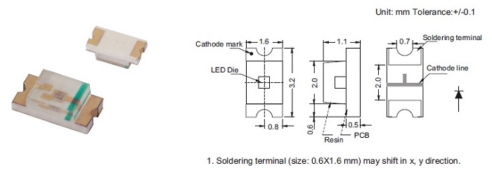
This is the result after doing some "repairs". The LEDs were soldered in the wrong way, contrary to how they should go. Take a look at the diagram below, the LEDs have a mark that tells us what the cathode is. I realized that they were bad soldiers because programming did not work.
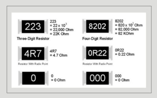
Another problem I found when I tried to operate the boards was that the LEDs did not turn on. They were well welded but I think the resistances were too big and there was enough power to turn on the LEDs. The original scheme of Neil marked resisitencias of 1K, I have changed them by resistances of 0.49 ohm (1 / 2K) and it worked!
The image below will help us understand how to read the value of the resistances
Programming the board
Once the boards are ready is time to upload the c code.
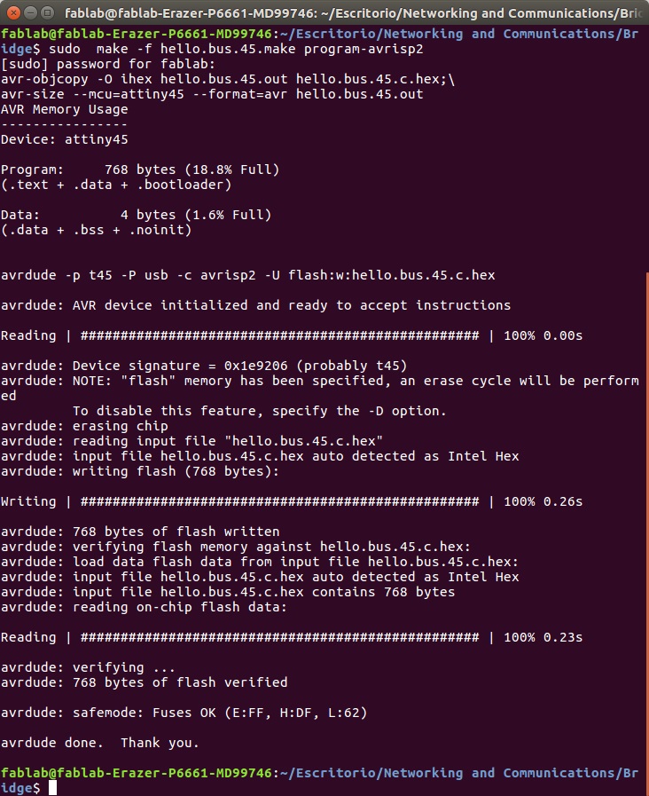
With the c file and make file on same folder I used avrdude/GCC for uploading the code.
On terminal I located my folder with the c and make file.
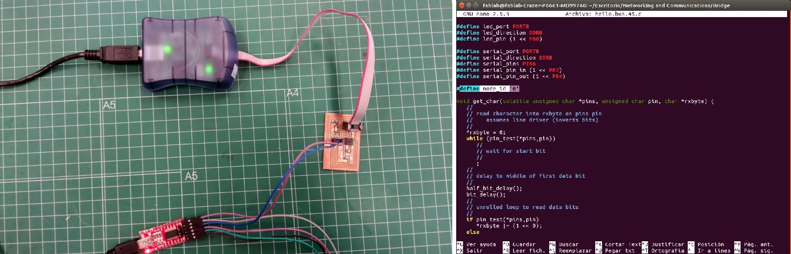
On the c file you need to change the #define node_id '0' for each node.
I used, for the bridge board: #define node_id '0'
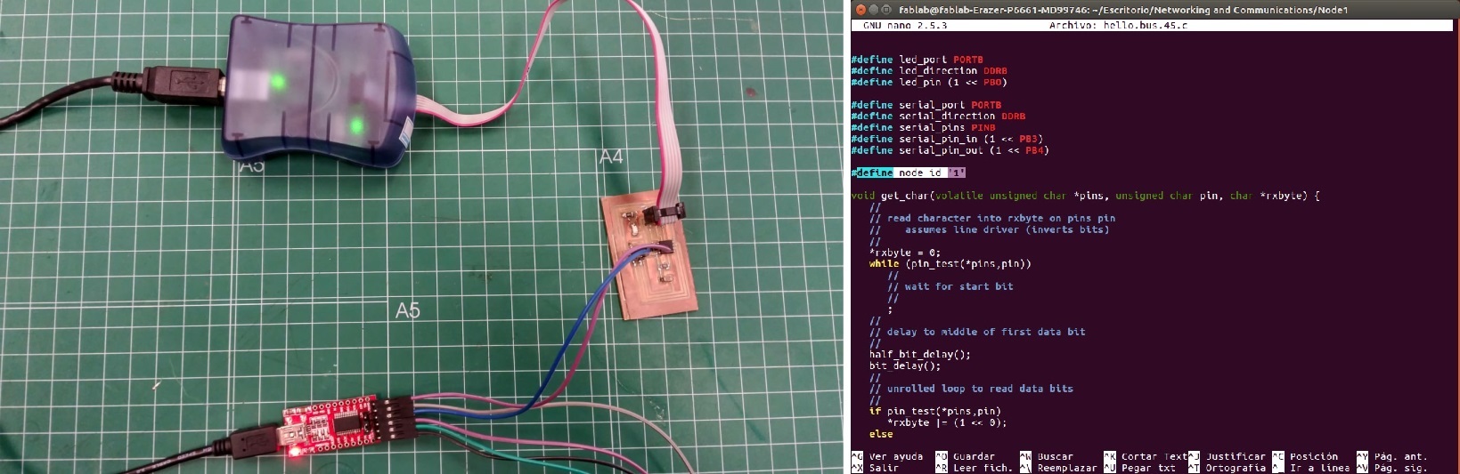
For the first node: #define node_id '1'
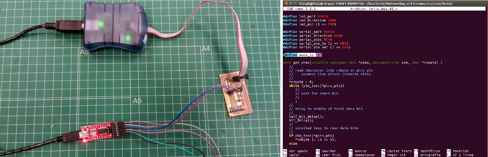
For the second node: #define node_id '2' And type the "sudo make -f hello.bus.45.make program-avrisp2" or "sudo make -f hello.bus.45.make program-usbtiny". For each board.
The workflow you should follow is: first connect the bridge board on one side to the FTDI and on the other to the FabISP or AVRISP and program it with the make file and c file that you change the node id to 0. Then you connect the first node to the bridge with the network cable and the FabISP or AVRISP and program it qith the c and make file that have the node id set as 1.
Finally, you connect the the last node and follow the same workflow as node 1.
Neil's code
//
		// hello.bus.45.c
//
// 9600 baud serial bus hello-world
//
// Neil Gershenfeld
// 11/24/10
//
// (c) Massachusetts Institute of Technology 2010
// Permission granted for experimental and personal use;
// license for commercial sale available from MIT.
//

#include
#include
#include
#include

#define output(directions,pin) (directions |= pin) // set port direction for output
#define input(directions,pin) (directions &= (~pin)) // set port direction for input
#define set(port,pin) (port |= pin) // set port pin
#define clear(port,pin) (port &= (~pin)) // clear port pin
#define pin_test(pins,pin) (pins & pin) // test for port pin
#define bit_test(byte,bit) (byte & (1 << bit)) // test for bit set
#define bit_delay_time 100 // bit delay for 9600 with overhead
#define bit_delay() _delay_us(bit_delay_time) // RS232 bit delay
#define half_bit_delay() _delay_us(bit_delay_time/2) // RS232 half bit delay
#define led_delay() _delay_ms(100) // LED flash delay

#define led_port PORTB
#define led_direction DDRB
#define led_pin (1 << PB0)

#define serial_port PORTB
#define serial_direction DDRB
#define serial_pins PINB
#define serial_pin_in (1 << PB3)
#define serial_pin_out (1 << PB4)

#define node_id '0'

void get_char(volatile unsigned char *pins, unsigned char pin, char *rxbyte) {
   //
   // read character into rxbyte on pins pin
   //    assumes line driver (inverts bits)
   //
   *rxbyte = 0;
   while (pin_test(*pins,pin))
      //
      // wait for start bit
      //
      ;
   //
   // delay to middle of first data bit
   //
   half_bit_delay();
   bit_delay();
   //
   // unrolled loop to read data bits
   //
   if pin_test(*pins,pin)
      *rxbyte |= (1 << 0);
   else
      *rxbyte |= (0 << 0);
   bit_delay();
   if pin_test(*pins,pin)
      *rxbyte |= (1 << 1);
   else
      *rxbyte |= (0 << 1);
   bit_delay();
   if pin_test(*pins,pin)
      *rxbyte |= (1 << 2);
   else
      *rxbyte |= (0 << 2);
   bit_delay();
   if pin_test(*pins,pin)
      *rxbyte |= (1 << 3);
   else
      *rxbyte |= (0 << 3);
   bit_delay();
   if pin_test(*pins,pin)
      *rxbyte |= (1 << 4);
   else
      *rxbyte |= (0 << 4);
   bit_delay();
   if pin_test(*pins,pin)
      *rxbyte |= (1 << 5);
   else
      *rxbyte |= (0 << 5);
   bit_delay();
   if pin_test(*pins,pin)
      *rxbyte |= (1 << 6);
   else
      *rxbyte |= (0 << 6);
   bit_delay();
   if pin_test(*pins,pin)
      *rxbyte |= (1 << 7);
   else
      *rxbyte |= (0 << 7);
   //
   // wait for stop bit
   //
   bit_delay();
   half_bit_delay();
   }

void put_char(volatile unsigned char *port, unsigned char pin, char txchar) {
   //
   // send character in txchar on port pin
   //    assumes line driver (inverts bits)
   //
   // start bit
   //
   clear(*port,pin);
   bit_delay();
   //
   // unrolled loop to write data bits
   //
   if bit_test(txchar,0)
      set(*port,pin);
   else
      clear(*port,pin);
   bit_delay();
   if bit_test(txchar,1)
      set(*port,pin);
   else
      clear(*port,pin);
   bit_delay();
   if bit_test(txchar,2)
      set(*port,pin);
   else
      clear(*port,pin);
   bit_delay();
   if bit_test(txchar,3)
      set(*port,pin);
   else
      clear(*port,pin);
   bit_delay();
   if bit_test(txchar,4)
      set(*port,pin);
   else
      clear(*port,pin);
   bit_delay();
   if bit_test(txchar,5)
      set(*port,pin);
   else
      clear(*port,pin);
   bit_delay();
   if bit_test(txchar,6)
      set(*port,pin);
   else
      clear(*port,pin);
   bit_delay();
   if bit_test(txchar,7)
      set(*port,pin);
   else
      clear(*port,pin);
   bit_delay();
   //
   // stop bit
   //
   set(*port,pin);
   bit_delay();
   //
   // char delay
   //
   bit_delay();
   }

void put_string(volatile unsigned char *port, unsigned char pin, PGM_P str) {
   //
   // send character in txchar on port pin
   //    assumes line driver (inverts bits)
   //
   static char chr;
   static int index;
   index = 0;
   do {
      chr = pgm_read_byte(&(str[index]));
      put_char(&serial_port, serial_pin_out, chr);
      ++index;
      } while (chr != 0);
   }

void flash() {
   //
   // LED flash delay
   //
   clear(led_port, led_pin);
   led_delay();
   set(led_port, led_pin);
   }

int main(void) {
   //
   // main
   //
   static char chr;
   //
   // set clock divider to /1
   //
   CLKPR = (1 << CLKPCE);
   CLKPR = (0 << CLKPS3) | (0 << CLKPS2) | (0 << CLKPS1) | (0 << CLKPS0);
   //
   // initialize output pins
   //
   set(serial_port, serial_pin_out);
   input(serial_direction, serial_pin_out);
   set(led_port, led_pin);
   output(led_direction, led_pin);
   //
   // main loop
   //
   while (1) {
      get_char(&serial_pins, serial_pin_in, &chr);
      flash();
      if (chr == node_id) {
         output(serial_direction, serial_pin_out);
         static const char message[] PROGMEM = "node ";
         put_string(&serial_port, serial_pin_out, (PGM_P) message);
         put_char(&serial_port, serial_pin_out, chr);
         put_char(&serial_port, serial_pin_out, 10); // new line
         led_delay();
         flash();
         input(serial_direction, serial_pin_out);
         }
      }
   }
Understanding the code
Once I have read Neil's code, I proceed to analyse it to understand how it works.
First of all, some headers must be included that have been used in previous assignments such as avr/io.h, util/delay.h and avr/pgmspace.h. In addition to this headers, the string.h header is also used, which contains some functions for manipulating arrays of characters.
After that, some macros are defined, which will be used in our program, apart from defining all the constants related to the LED (port, direction and pin) and serial (port, direction and output/input pins).
To read any character that is send through RX byte, the get_char function is used which reads each data bit that has been sent to a specified pin. On the other hand, we have the put_char function that sends a character through the TX byte. This function will be also used in put_string which allows us to send an array of characters. Apart from those functions, there is also one called flash that just blinks the desired LED once.
Finally, I analyse the main function, starting setting CLKPR to divide clock by 1 in order to run at 8 MHz without messing with Lfuse. For this reason CLKPCE must be set(CLocK Prescaler Enable) to 1, as well as CLKPS3, CLKPS2, CLKPS1 and CLKPS0 to 0. Once this task is done, we proceed to initialize output pins and enter the main loop. In this loop, we will be continously reading if any character has been sent to the serail pin and if this character is equal to the node_id we will flash the LED of the corresponding node. What's more, a message will be sent to the serial showing which node has been flashed.


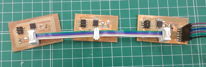
Bridge-node1-node2 should be connected like this
Next, you load the Arduino IDE, and click on the Serial Monitor button. On the Serial Monitor window you type 0, 1 or 2 and press enter after the node you typed. Then you should get your boards react. All the leds should blink once and the node selected should blink once and get a response on the serial monitor window
Neil's code modified
//
		// hello.bus.45.c
//
// 9600 baud serial bus hello-world
//
// Neil Gershenfeld
// 11/24/10
//
// Modiified by Javier Hernandez
// 07/04/2018
//
// (c) Massachusetts Institute of Technology 2010
// Permission granted for experimental and personal use;
// license for commercial sale available from MIT.
//

#include
#include
#include
#include

#define output(directions,pin) (directions |= pin) // set port direction for output
#define input(directions,pin) (directions &= (~pin)) // set port direction for input
#define set(port,pin) (port |= pin) // set port pin
#define clear(port,pin) (port &= (~pin)) // clear port pin
#define pin_test(pins,pin) (pins & pin) // test for port pin
#define bit_test(byte,bit) (byte & (1 << bit)) // test for bit set
#define bit_delay_time 100 // bit delay for 9600 with overhead
#define bit_delay() _delay_us(bit_delay_time) // RS232 bit delay
#define half_bit_delay() _delay_us(bit_delay_time/2) // RS232 half bit delay
#define led_delay() _delay_ms(100) // LED flash delay

#define led_port PORTB
#define led_direction DDRB
#define led_pin (1 << PB0)

#define serial_port PORTB
#define serial_direction DDRB
#define serial_pins PINB
#define serial_pin_in (1 << PB3)
#define serial_pin_out (1 << PB4)

#define node_id '0'

int ON = 0;

void get_char(volatile unsigned char *pins, unsigned char pin, char *rxbyte) {
   //
   // read character into rxbyte on pins pin
   //    assumes line driver (inverts bits)
   //
   *rxbyte = 0;
   while (pin_test(*pins,pin))
      //
      // wait for start bit
      //
      ;
   //
   // delay to middle of first data bit
   //
   half_bit_delay();
   bit_delay();
   //
   // unrolled loop to read data bits
   //
   if pin_test(*pins,pin)
      *rxbyte |= (1 << 0);
   else
      *rxbyte |= (0 << 0);
   bit_delay();
   if pin_test(*pins,pin)
      *rxbyte |= (1 << 1);
   else
      *rxbyte |= (0 << 1);
   bit_delay();
   if pin_test(*pins,pin)
      *rxbyte |= (1 << 2);
   else
      *rxbyte |= (0 << 2);
   bit_delay();
   if pin_test(*pins,pin)
      *rxbyte |= (1 << 3);
   else
      *rxbyte |= (0 << 3);
   bit_delay();
   if pin_test(*pins,pin)
      *rxbyte |= (1 << 4);
   else
      *rxbyte |= (0 << 4);
   bit_delay();
   if pin_test(*pins,pin)
      *rxbyte |= (1 << 5);
   else
      *rxbyte |= (0 << 5);
   bit_delay();
   if pin_test(*pins,pin)
      *rxbyte |= (1 << 6);
   else
      *rxbyte |= (0 << 6);
   bit_delay();
   if pin_test(*pins,pin)
      *rxbyte |= (1 << 7);
   else
      *rxbyte |= (0 << 7);
   //
   // wait for stop bit
   //
   bit_delay();
   half_bit_delay();
   }

void put_char(volatile unsigned char *port, unsigned char pin, char txchar) {
   //
   // send character in txchar on port pin
   //    assumes line driver (inverts bits)
   //
   // start bit
   //
   clear(*port,pin);
   bit_delay();
   //
   // unrolled loop to write data bits
   //
   if bit_test(txchar,0)
      set(*port,pin);
   else
      clear(*port,pin);
   bit_delay();
   if bit_test(txchar,1)
      set(*port,pin);
   else
      clear(*port,pin);
   bit_delay();
   if bit_test(txchar,2)
      set(*port,pin);
   else
      clear(*port,pin);
   bit_delay();
   if bit_test(txchar,3)
      set(*port,pin);
   else
      clear(*port,pin);
   bit_delay();
   if bit_test(txchar,4)
      set(*port,pin);
   else
      clear(*port,pin);
   bit_delay();
   if bit_test(txchar,5)
      set(*port,pin);
   else
      clear(*port,pin);
   bit_delay();
   if bit_test(txchar,6)
      set(*port,pin);
   else
      clear(*port,pin);
   bit_delay();
   if bit_test(txchar,7)
      set(*port,pin);
   else
      clear(*port,pin);
   bit_delay();
   //
   // stop bit
   //
   set(*port,pin);
   bit_delay();
   //
   // char delay
   //
   bit_delay();
   }

void put_string(volatile unsigned char *port, unsigned char pin, PGM_P str) {
   //
   // send character in txchar on port pin
   //    assumes line driver (inverts bits)
   //
   static char chr;
   static int index;
   index = 0;
   do {
      chr = pgm_read_byte(&(str[index]));
      put_char(&serial_port, serial_pin_out, chr);
      ++index;
      } while (chr != 0);
   }

void LED(void) {
   //
   // Turn ON/OFF LED
   //

    if (ON == 0)
    {
       ON = 1;
       clear(led_port, led_pin);
    }
    else
    {
       ON = 0;
       set(led_port, led_pin);
    }
   }

int main(void) {
   //
   // main
   //
   static char chr;
   //
   // set clock divider to /1
   //
   CLKPR = (1 << CLKPCE);
   CLKPR = (0 << CLKPS3) | (0 << CLKPS2) | (0 << CLKPS1) | (0 << CLKPS0);
   //
   // initialize output pins
   //
   set(serial_port, serial_pin_out);
   input(serial_direction, serial_pin_out);
   set(led_port, led_pin);
   output(led_direction, led_pin);
   //
   // main loop
   //
   while (1) {
      get_char(&serial_pins, serial_pin_in, &chr);

      if (chr == node_id) {
         output(serial_direction, serial_pin_out);
         static const char message[] PROGMEM = "turning node ";
         static const char messageON[] PROGMEM = " ON";
         static const char messageOFF[] PROGMEM = " OFF";
         put_string(&serial_port, serial_pin_out, (PGM_P) message);
         put_char(&serial_port, serial_pin_out, chr);

         if (ON == 0)
         {
             put_string(&serial_port, serial_pin_out, (PGM_P) messageON);
         }

         else
         {
             put_string(&serial_port, serial_pin_out, (PGM_P) messageOFF);
         }

         put_char(&serial_port, serial_pin_out, 10); // new line
         led_delay();
         LED();
         input(serial_direction, serial_pin_out);
         }
Modifying the code
After I have tested Neil's code, I have decide to introduce some modifications in order to change the way we interact with each LEDs. Instead of flashing the desired node's LED, I think it could be more useful to turn on or turn off each LED separately, as if we had a switch for each node that I will be able to control from the Arduino's Serial Monitor.
To reach this objective, I need another variable, which I called ON, that will represent the LED's state (OFF = 0; ON = 1). Besides, I have replaced the flash function with the LED function, which will turn on or turn off the LED according to its previous state, and the text that is shown in the Arduino's Serial Monitor by a message that points out which node is being turned on/off.