4 Axis CNC Hot Wire Foam Cutting Machine
Interface
1 Interface Systems.
2 Design Rules.
3 Gcode Generator.
4 Sender.
5 Firmware.
6 Conclusions, What would I change?
1 Interface Systems
SchemeThe machine is divided into 3 systems that work independently.

In the case of the Wire Tensor System and the Wire Heating System, we can talk about a mechanical or physical interface, without the need for a computer or software to act.
Although in the Wire Tensor System the Fabduino board must be programmed, once programmed it works in a independent way, it is only necessary to connect it to the pack of batteries.
In the case of Wire Heating System, we use a bench power supply, we just need to turn it on and turn the button that regulates the intensity.
In the 4 Axis Machine Movement System we can talk about an informatic Interface, we use a software to 'talk' to the machine. This what I'm going to explain.
4 Axis Machine Movement System Interface
- Design: 3d Model to be cutted. there are rules for the design models.
- Gcode Generator: Generators are programs that take some sort of input file (STL, DXF, BMP, etc.) and transform it into machine specific code with its different performance characteristics or setups.
- Sender: Gcode platform used for interfacing with advanced CNC controllers
- Firmware: Software that is embedded in a piece of hardware.
Scope of the interface projectMaking this machine has been somewhat complex for me, although at first glance some things seem simple these have needed a learning. How to operate the machine and understand it has been complex for me.
While it is logical that a gecodes generator is necessary to carry out the work I have focused on making the machine work and move, and this can be done with the 'Sender'
Anyway I will explain which gcode generator I have contemplated to use with the machine and what features it has
2 Design Rules
As every machine this has its rules, design rules. We can not ask the machine to do something it can not do.
3d ModelThis machine was conceived to manufacture wing profiles, that is to join one profile with another, from one major to one minor or two igulaes profiles. It is not possible to cut a design that has a major / minor / major combination. See images below


When the design is of a larger profile than a smaller one, the stock size must be bigger than that the model in height and depth (Y, Z) and must have the same model width (X).
When the design has equal profiles, the stock size must be bigger than the model in height and depth (Y, Z) and the width can be equal or bigger than the model.
When I started thinking about the project, the idea arose that it would be parametric but when developing the project I realized that it has to be parametric if we want to cut models that have different profiles
So every time we go to do a job we must move one of the towers adjusting the distance to the width of the stock
3 Gcode Generator
This part of the process is very important to be able to perform the type of jobs for which the machine has been designed. A good Gcodes generator can make a difference when you're doing a job
What is a Gcode GeneratorGenerators are programs that take some sort of input file (STL, DXF, BMP, etc.) and transform it into machine specific code with its different performance characteristics or setups.
DevFoam softwareIt's an applications to cut foam by a 4 axis hot wire CNC.
This software has different version whith different features
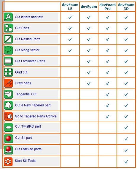
I had been playing with the 'devFoam Pro' version and in my opinon it has a very complete pack of features and setups.
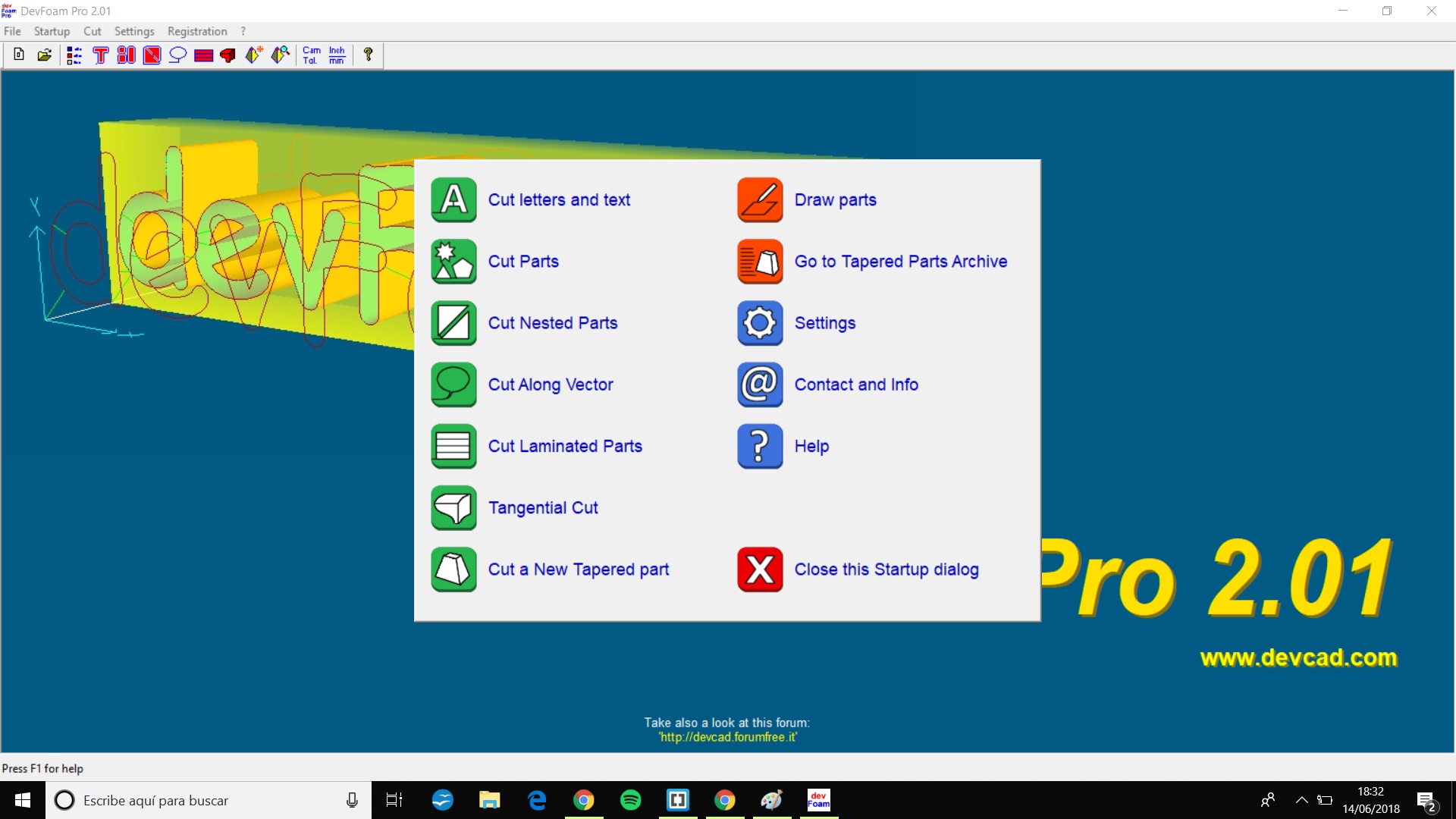
is what we see when we open the software, I will choose the last option "Cut a new tappered part".

A window that informs that the firt file to select will be de left side and the second the right one..
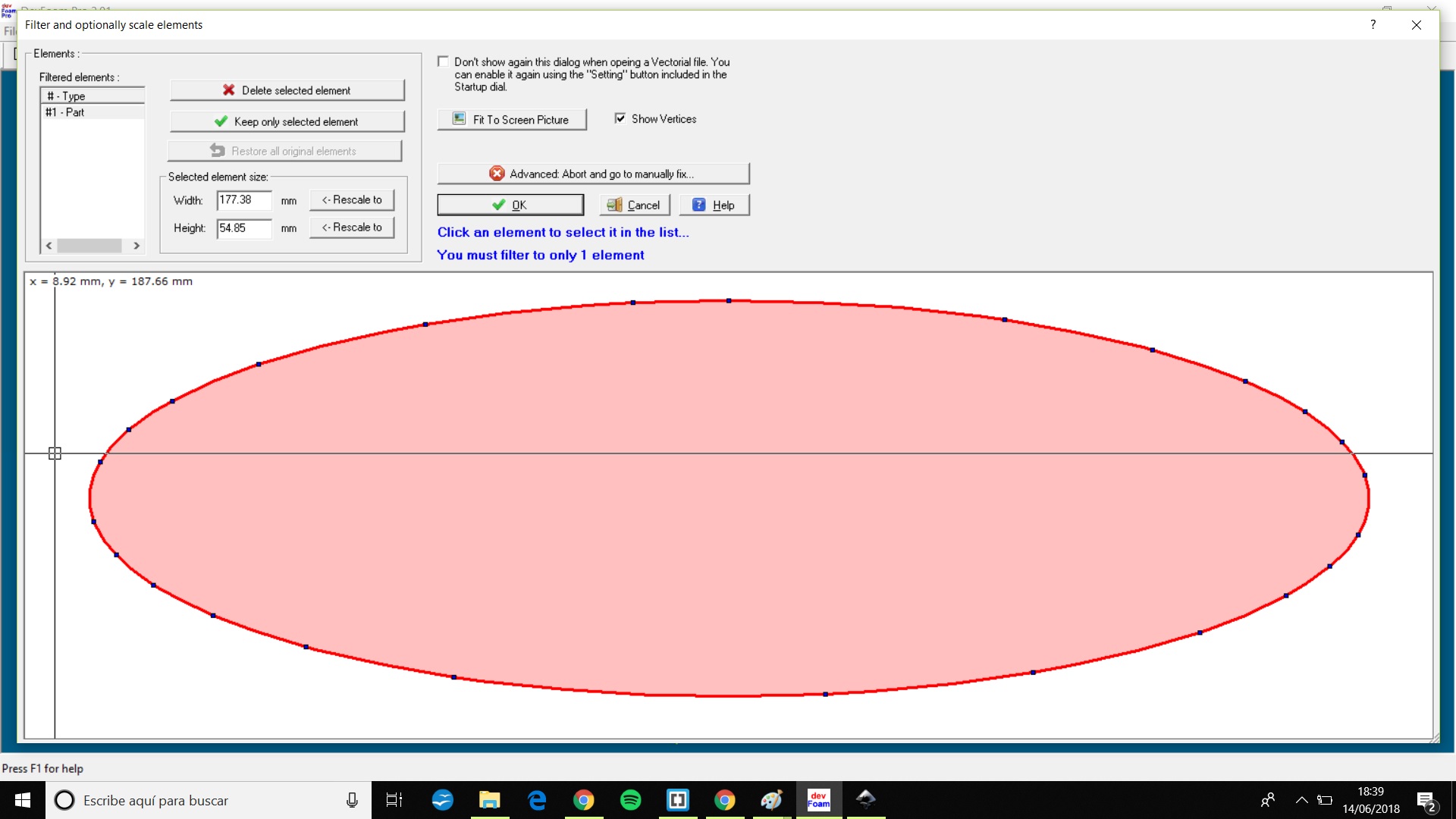
I made an oval.

Thewn a rectagle.

In this window we manege the start point of cutting.

In the previous window there's an option to see a 3D Preview.

In this window we move the different parts and set the Foam block dimensions and placement.
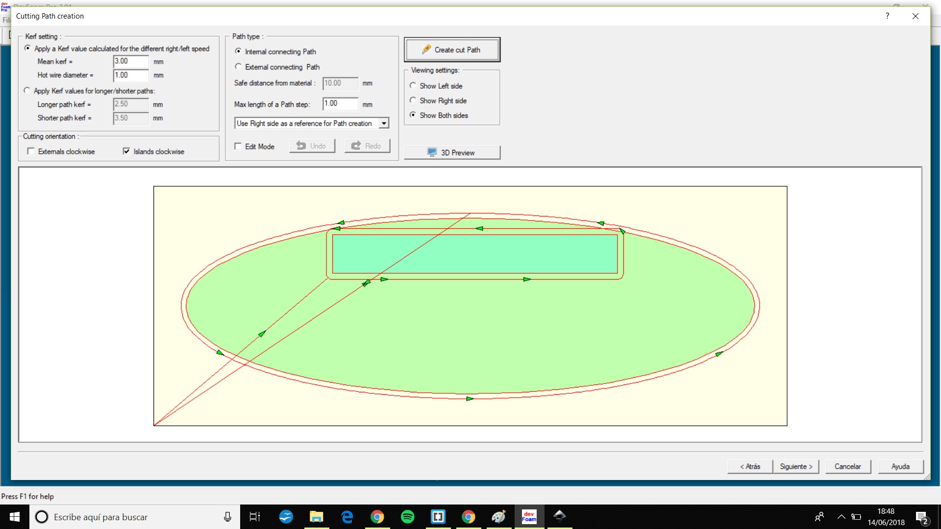
In this window we create a cut path and setup Kerf values and hot wire diameter.
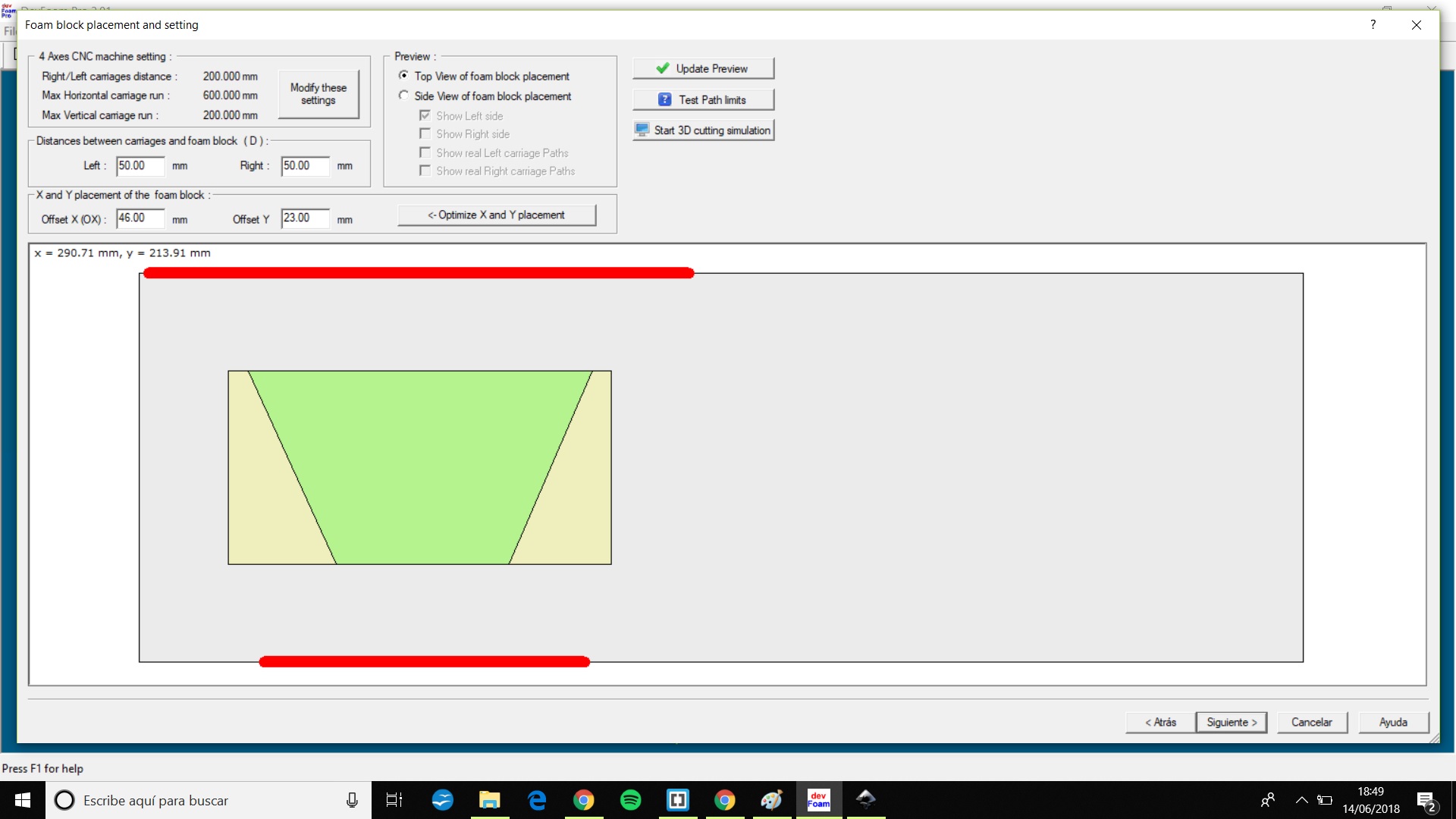
Here we can set the position of the foam block into the x axis.
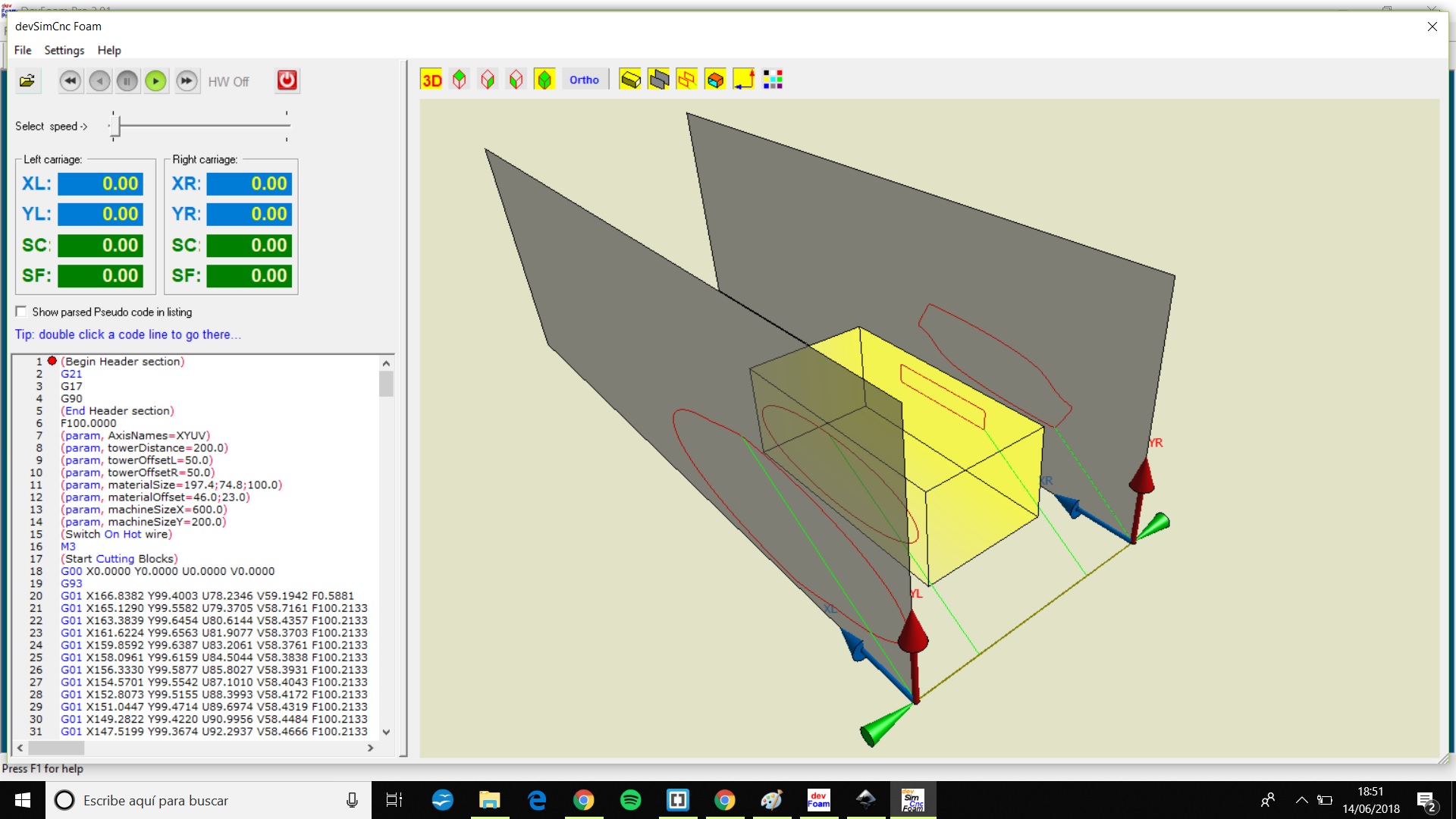
A 3D preview with the block.
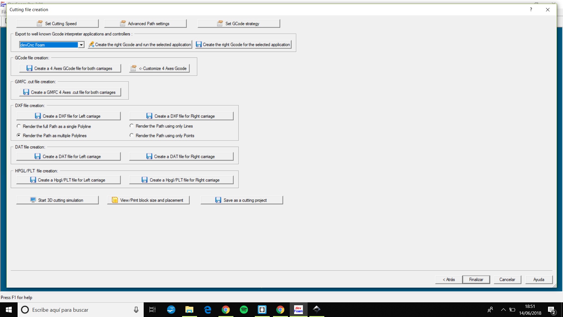
Different way to save the work.
I didn't found any good tuto but here is a forum from devcad.
4 Sender
A full featured gcode platform used for interfacing with advanced CNC controllers like GRBL and TinyG. Universal Gcode Sender is a self-contained Java application which includes all external dependencies, that means if you have the Java Runtime Environment setup UGS provides the rest.
You can download the universal gcode sender UGS here

I downloaded the 1.0.9 version
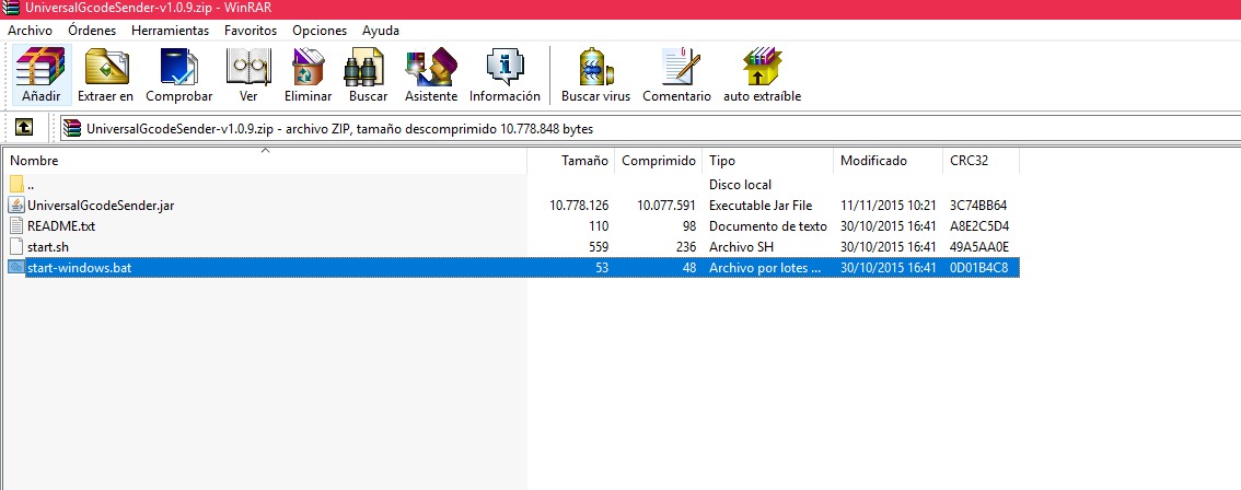
decompress and click on the .bat file and the UGS window will appear
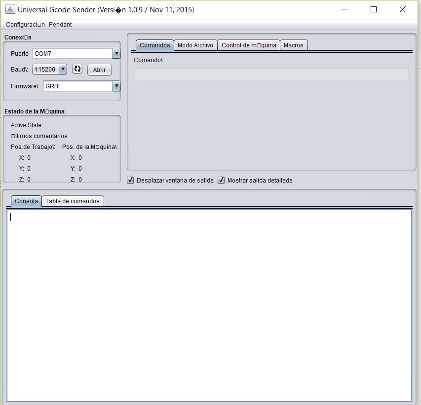
Before anything, read this It is a little dense but indispensable
once connected to the port (which will auto detect it) we can write in the command line
there the first execution we will change the parameters of the accelerations and number of steps and the direction of each of the axes
$100, $101 and $102 – [X,Y,Z] steps/mm
The full steps per revolution of your steppers (typically 200). The microsteps per step of your controller (typically 1, 2, 4, 8, or 16)
$120, $121, $122 – [X,Y,Z] Acceleration, mm/sec^2
A lower value makes Grbl ease slower into motion, while a higher value yields tighter moves and reaches the desired feed rates much quicker
UGS has it's default values, check what happens with the default values and star changing the values until you feel it's ok, i didn't find a way to measure this.
This setup is saved at the Arduino Eprom (Erasable Programmable Read-Only Memory)
$130, $131, $132 – [X,Y,Z] Max travel, mm
This sets the maximum travel from end to end for each axis in mm. This is the large of the Z and Y axis.
G28: Move to Origin (Home)
When the firmware receives this command, it moves all (or the supplied) axis's back to the zero endstops as quickly as it can
when the arduino is restarted it is when it is believed that it is in the 0 0 0 0
Now we can move the machine by writing in the console window
For example
G00
X20
Y20
Z40
A40
G00 is fast forward, and yes, there's an A, the senders are made ussually for 3 axis machine but we can type A as another axis and the sender will understand it.
5 Firmware
This is the firmware to upload to the arduino mega2560
Note: This part of the process has to be done before enter any data in the universal gcode sender.
6 Conclusions, What would I change?
It is difficult to say that it could change without having similar experiences with which to compare
I would have made a simpler project, a smaller one.
Background
Machine
Electronics
Interface

This work is licensed under a Creative Commons Attribution-NonComercial ShareAlike 3.0 Unported. International License.