4 Axis CNC Hot Wire Foam Cutting Machine
Electronics
1 Electronics concept.
2 Wire Tensor System.
3 Four axis machine movement system.
4 Wire Heating System.
5 Conclusions, What would I change?
1 Electronics concept
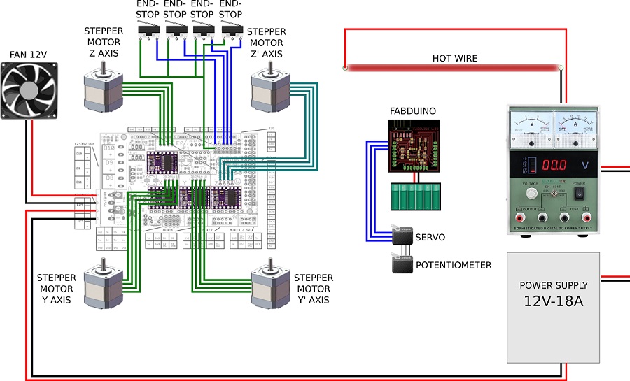
Machine SystemsThe machine is divided into 3 systems that work independently.

The 4 axix machine movement system will take care of the operation of the stepper motors, end-stop sensors input and manage the information received by the gcode sender.
The wire tensor system will take care of receive the information about the tension of the wire and rectify in a positive or negative way, wind and unwind the wire.
the wire heating system will take care of transmit electricity to the cable to heat it in the right intensity.
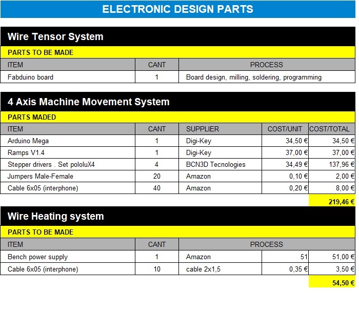
Material List
2 Wire Tensor System
The idea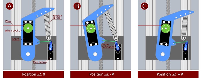
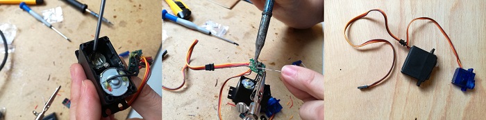
Another important design solution has been the system to maintain the tension of the hot wire. In addition to using a tension spring, a servo motor is used to wind or unwind the hot wire spool and another servo to define the correct position of the tensioning arm. To the first servo we remove the potentiometer so that it only works as a motor without feedback and the other servo we remove the engine so that its only function is to send a feddback. Besides the servos we will need a controller board. Fabduino
References:
To make this board I have reviewed some projects. check this:
Instructables / Tiffany Tseng / Haldin Anders
Scheme

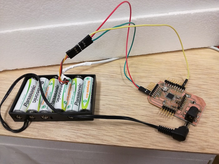
I will upgrade the Fabduino board, I will add a 2.1mm jack to power the board with batteries. In order to add the Jack it is necessary to put a regulator.
A voltage regulator is an electronic circuit that provides a stable DC voltage independent of the load current, temperature and AC line voltage variations.
A simple voltage/current regulator can be made from a resistor in series with a diode (or series of diodes). Due to the logarithmic shape of diode V-I curves, the voltage across the diode changes only slightly due to changes in current drawn or changes in the input. When precise voltage control and efficiency are not important, this design may be fine. Since the forward voltage of a diode is small, this kind of voltage regulator is only suitable for low voltage regulated output
How to calculate the regulator / Online calculator
Devices list

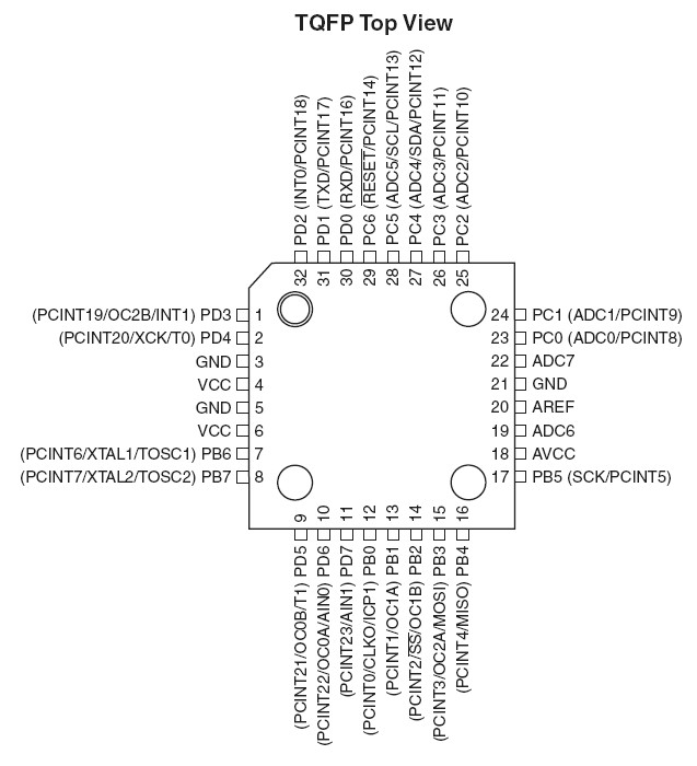
For rhis board we will use a ATmega48. Datasheet
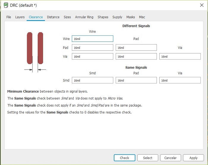
Eagle design

In this design i use welded pinheaders instead of drilling for pinning. Also i decide using a 0,02 tool for milling (traces) looking for more precision, this change it's reflected on the Eagle DRC setup setup window.


Milling png's

A text, just to see what happens.
The workflow for cutting out your board is as follows
- Cut out the traces using the 0,02mm endmill (traces file)
- Mill out the holes using the 0,7mm endmill (holes file)
- Cut out the board using the 0,7mm endmill
Milling result

The text experiment failed, i will try again in other time, maybe changing the tool because this tool is in it's finals days. After this you should check continuity with a voltimeter to ensure there's no broken trace.
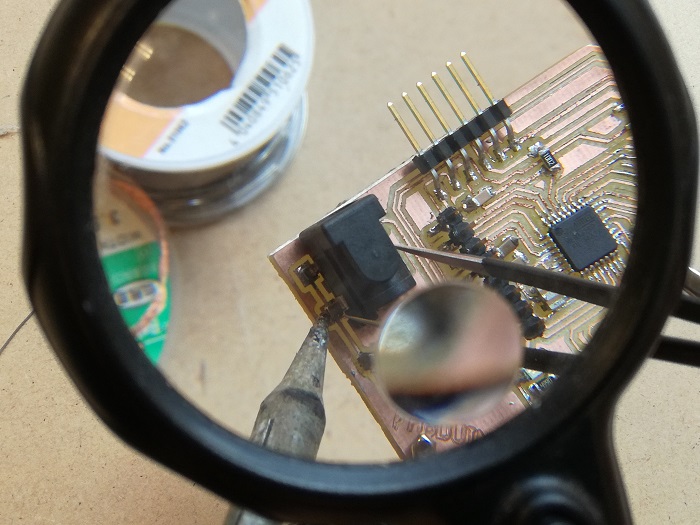
It has not been easy, the tracks are a bit mistreated since the milling bit was a bit worn.
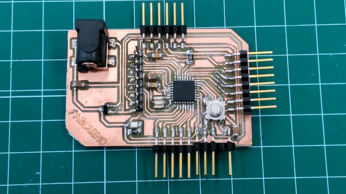
Finally the board is finished
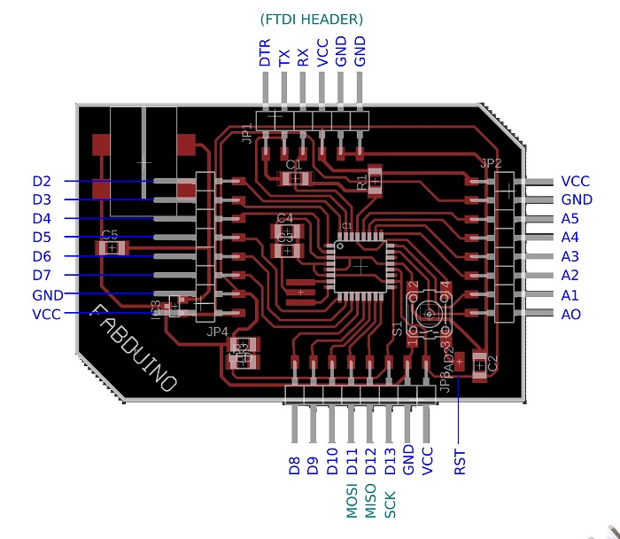
Fabduino Pinout
fabduino Programming

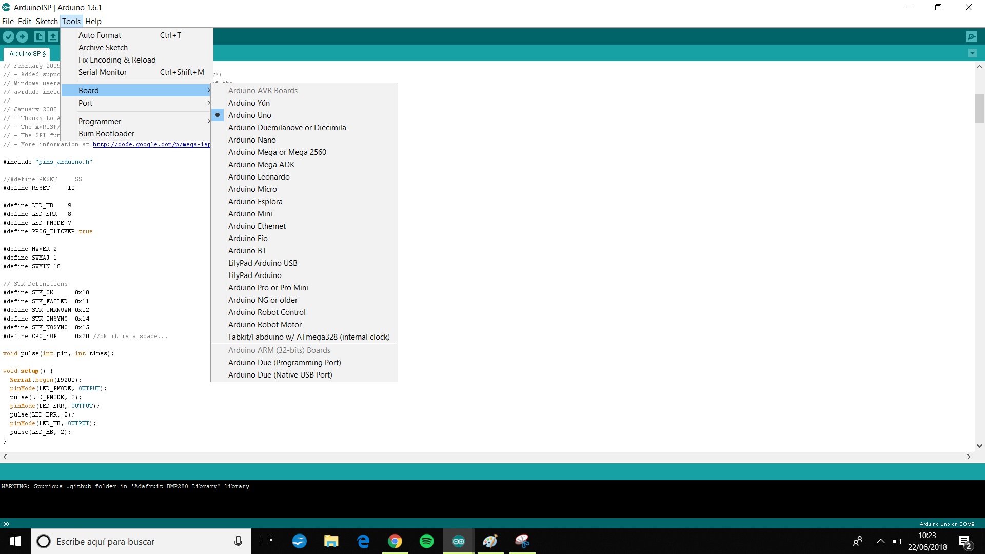
I took a Tutorial fron the Fabacademy 2015. and found that if I want to use it with the Arduino IDE, I need to add this text to the boards.txt files of the Arduino IDE installation:
//
fabduino.name=Fabkit/Fabduino w/ ATmega328 (internal clock)

fabduino.upload.protocol=stk500v1
fabduino.upload.maximum_size=14336
fabduino.upload.speed=19200

fabduino.bootloader.low_fuses=0xe2
fabduino.bootloader.high_fuses=0xdd
fabduino.bootloader.extended_fuses=0x00
fabduino.bootloader.path=arduino:atmega
fabduino.bootloader.file=atmega/ATmegaBOOT_168_atmega328_pro_8MHz.hex
fabduino.bootloader.unlock_bits=0x3F
fabduino.bootloader.lock_bits=0x0F

fabduino.build.mcu=atmega328p
fabduino.build.f_cpu=8000000L

fabduino.build.core=arduino:arduino
fabduino.build.variant=arduino:standard

fabduino.upload.tool=arduino:avrdude
fabduino.bootloader.tool=arduino:avrdude
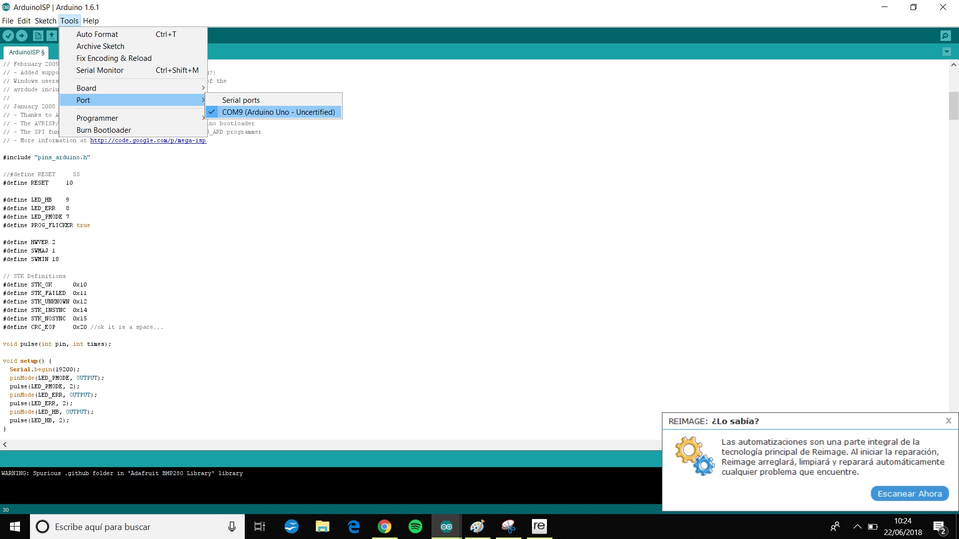
The tutorial explains that the Arduino IDE should be the v.1.6, I try using a newer version and... it didn't work, I spend time checking connections, solders and code until you reread the tutorial and do it with the IDE version that was proposed
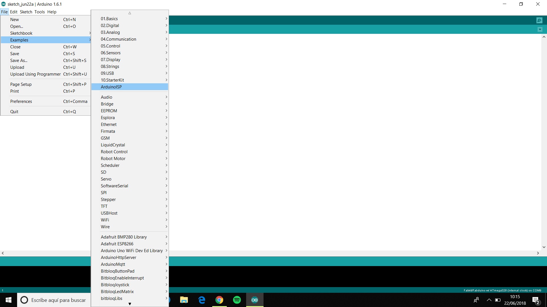
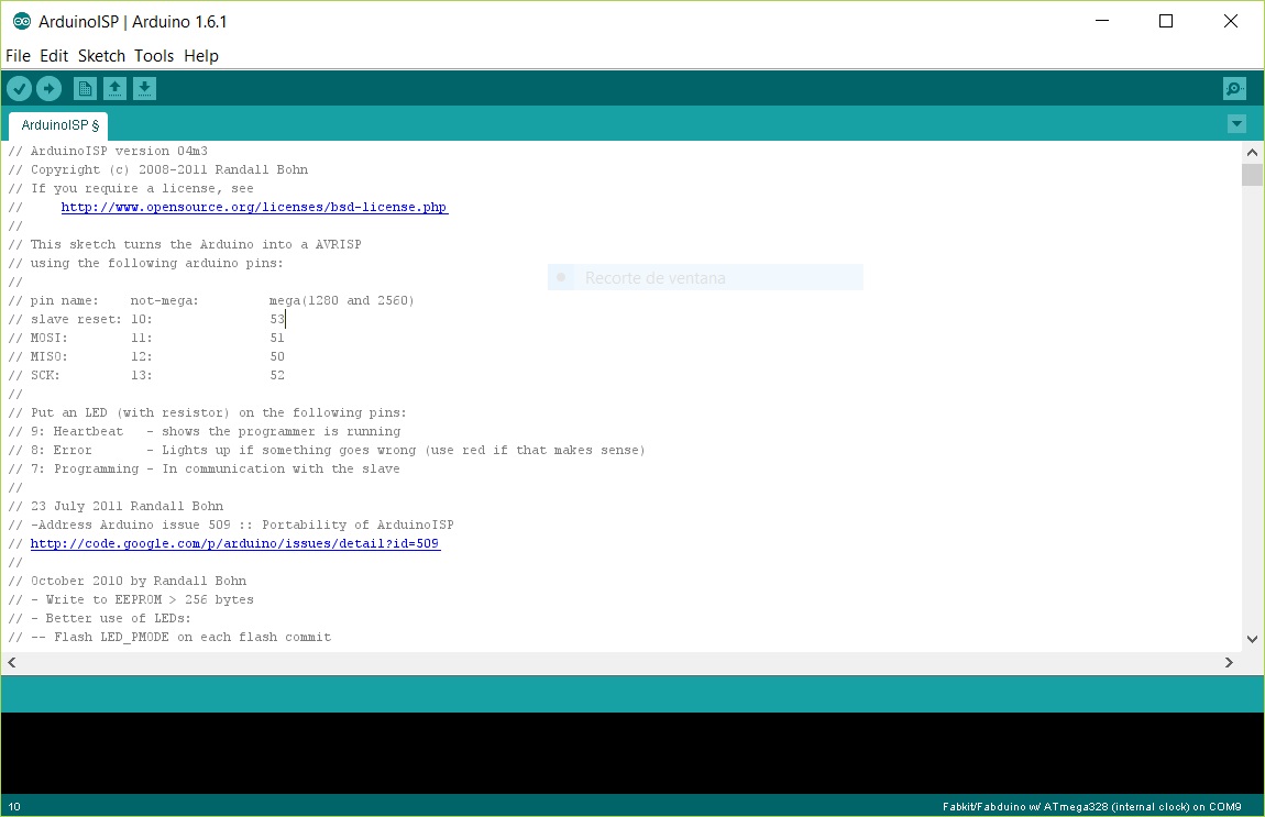
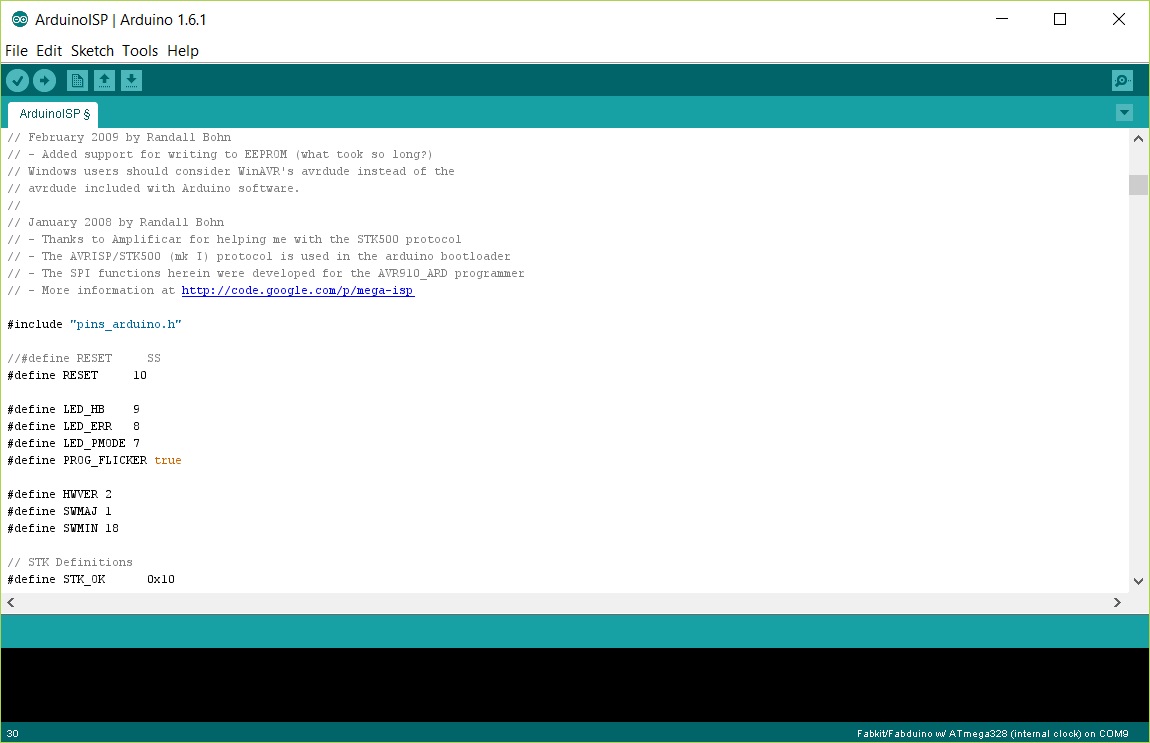
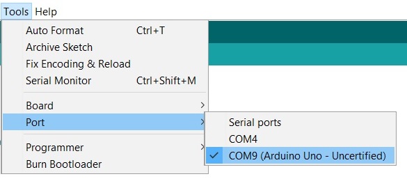
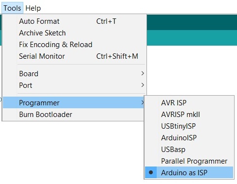
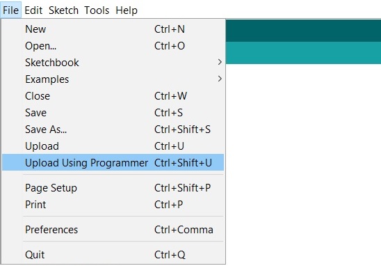
I used an arduino as an ISP to program the board. Follow the next steps.


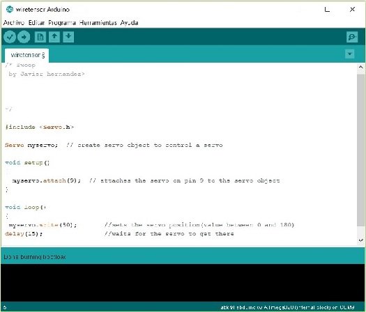
The position of the servo in the code is fixed at 90, it is possible that the "physical" position of the servo 90 is not the appropriate value, it is necessary to change the value until reaching the point where the cable is taut
Now we are ready to uoload the code to our Fabduino.


Connection scheme
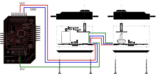
Check all the instructions to connect the servo motors at the Mechanical design page

3 Four axis machine movement system
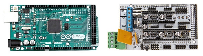
HardwareFor this part of the machine i will use a arduino mega, a ramps 1.4
To understand how it works and how to connect it is necessary to make some readings, check the liks below.
Connection scheme
Arduino Mega - Ramps
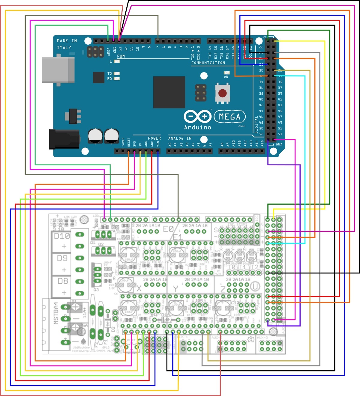
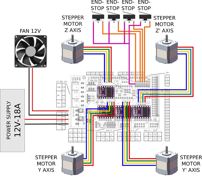
Ramps - Peripherals
it looks clearer in the scheme
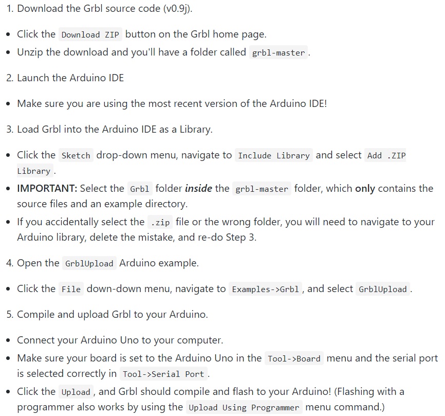
I've been doing some research and what some experts say the firmware that goes best for this project is the GRBL. We can get this firmware on the Git page
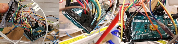
Testing
It is advisable to test the stepper motors and the mechanical endstops before assembling them. It is possible that some component does not work and we have to dismantle it to put a new one. It is also more comfortable to do it with all the stepper motors at hand in order to "feel" how they move.
To test the software, the connections, the stepper motors and the mechanical endstops we need a "Sender", we need a software to send information to the arduino board, i will explain it later but here is an scheme.

An important factor for a good functioning is the adjustment of the drivers, folow the link below to learn how to set the stepper divers
Setting stepper driver video.
4 Wire Heating System
subtitleThis system is indepent as the other two ones, once you have regulated the power you can stat working
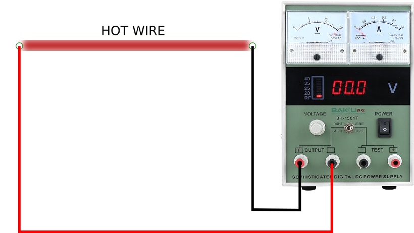
I initially tested with a 12v power supply for a distance of 80cms, then I tried a larger distance and the power was not enough, so I tried it with 24v and it worked.
The power supplies have a small regulator right next to the cable outlet.
I have to use a Bench power supply in order to have a parametric machine.
Power supply - bench power supply Read this

5 Conclusions, What would I change?
The board Fabduino is oversized for the work it performs, maybe a simpler board would have fulfilled the function. I have to say that making the fabduino was rewarding.
Background
Machine
Electronics
Interface

This work is licensed under a Creative Commons Attribution-NonComercial ShareAlike 3.0 Unported. International License.