Assignment:
A_ add an output device to a microcontroller board you've designed and program it to do something.
Design the board
I will start from the stepper motor controler board to which I would like to add a led pilot indicating the motor is running and a light sensor input. This will help the next assignment group project as we are planning to make a solar tracker.
A little bit about motors:
-A stepper motor is a type of DC motor which is any of a class of rotary electrical machines that converts direct current electrical energy into mechanical energy. The most common types rely on the forces produced by magnetic fields. Nearly all types of DC motors have some internal mechanism, either electromechanical or electronic, to periodically change the direction of current flow in part of the motor.
A stepper motor is a brushless DC electric motor that divides a full rotation into a number of equal steps. The motor's position can then be commanded to move and hold at one of these steps without any position sensor for feedback (an open-loop controller), as long as the motor is carefully sized to the application in respect to torque and speed.
The difference between a stepper motor adn a servo motor:
Servomotors are generally used as a high-performance alternative to the stepper motor. Stepper motors have some inherent ability to control position, as they have built-in output steps. This often allows them to be used as an open-loop position control, without any feedback encoder, as their drive signal specifies the number of steps of movement to rotate, but for this the controller needs to 'know' the position of the stepper motor on power up. Therefore, on first power up, the controller will have to activate the stepper motor and turn it to a known position, e.g. until it activates an end limit switch. The lack of feedback of a stepper motor limits its performance, as the stepper motor can only drive a load that is well within its capacity, otherwise missed steps under load may lead to positioning errors and the system may have to be restarted or recalibrated. The encoder and controller of a servomotor are an additional cost, but they optimise the performance of the overall system (for all of speed, power and accuracy) relative to the capacity of the basic motor. With larger systems, where a powerful motor represents an increasing proportion of the system cost, servomotors have the advantage.
There has been increasing popularity in closed loop stepper motors in recent years.[citation needed] They act like servomotors but have some differences in their software control to get smooth motion. The main benefit of a closed loop stepper motor is its relatively low cost. There is also no need to tune the PID controller on a closed loop stepper system.
Unipolar/vs/bipolar stepper motor
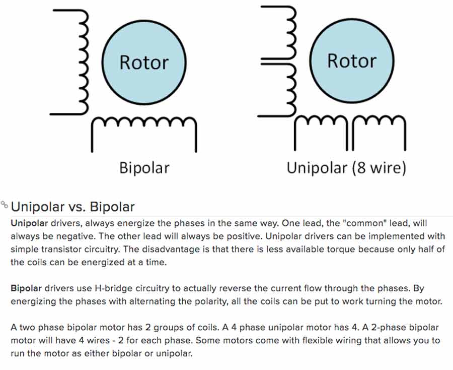
The nema 17 which I will use is a bipolar stepper motor and compatible with the class archive sample board that I am adapting. The led will also be an output - turns on when the motor is running, and the light sensor an input. In the original board we can see there are 4 pin free on the microcontroler (attiny44) which I can use for input and output.
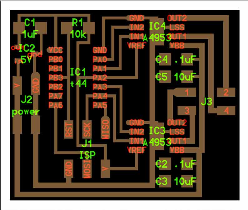
About the components. I researched in the Fab Academy archive to find example of students who have done this board and found this assignment that helped me with identifying the components.
The bipolar stepper motor circuit board uses 4 integrated circuits:
IC1: (1) Microcontroller Attiny44
IC2: (1) Power (voltage) regulator (sot23), limiting 5v for Attiny 44.
IC3: (2)IC4: H-bridge A4953) (to power the stepper motor).
The other components required are:
2 x 4pin header for power supply (5V)
1 x 6 pin header for data
3 x 1uF capacitator
2 x 10uF capacitator
1 x 10K resisitor
To this I will add:
1 x light sensor (LRD) or phototransistor
1 x 10k resistor
1 x led
1 x 499k resistor
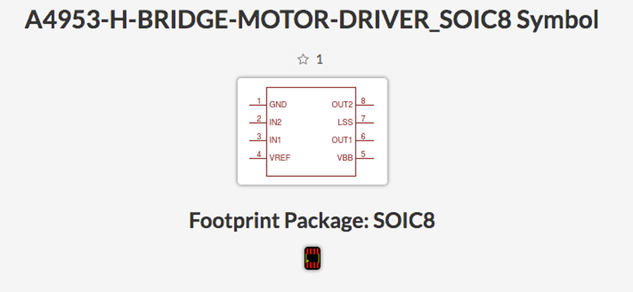
The power voltage and H-Bridge are new components and I did a little research to understand what they are, their functions and specifications.
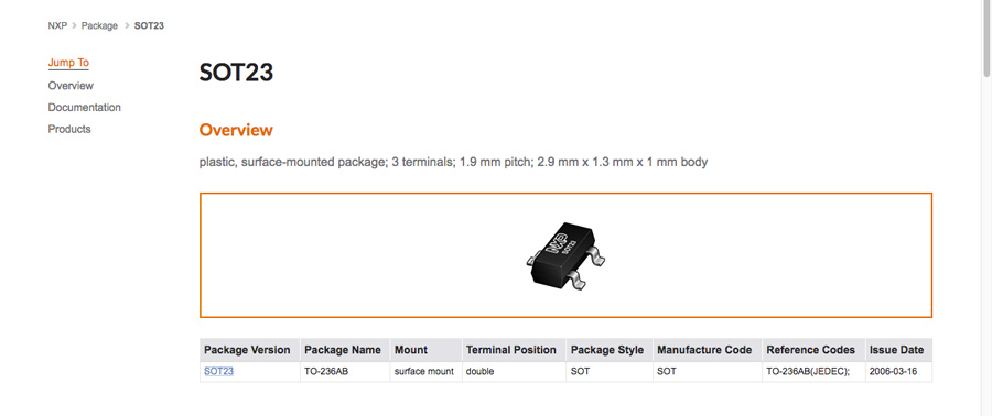
SOT 23 Voltage regulator

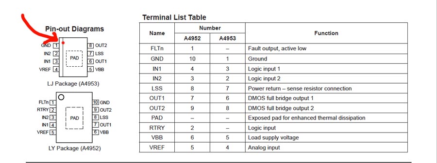

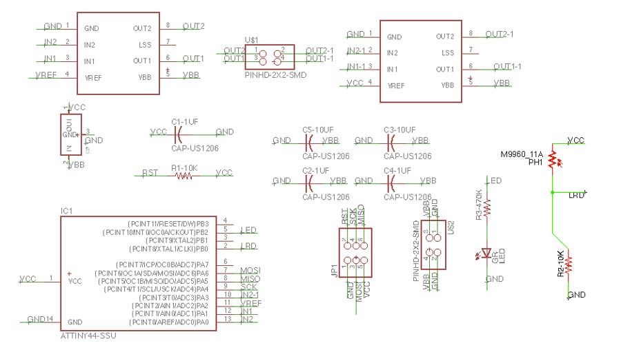
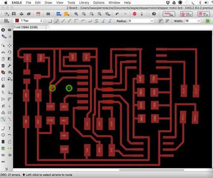
I created the schematic inserting the components I am adding and traced the routes. I did different versions of the routes and finally got a final one and went on milling. It took me a while to warm up on Eagle. I feel more comfortable to work with it even though I had some issues with overlapping error message when doing the traces. In some cases I could not match the names and that created conflicts (for Example Vref to V, PIN02 to Vref, etc.) and also when there are 2 components with different names connected to the same pin. (ex: Slk to PA4 to In1)
Finding the components in the library is another issue and understanding why this one more than another is still quite a dilemma but I did refer to datasheet and search the web for references.
One thing I am still not shure about is the difference between Vbb and Vcc. Looking at the board Vbb appears to be the trace that corresponds to the Voltage from power source to output of the H-bridge, the traces are wider on Neil's board probably because it is designed to carry higher voltage. Nevertheless on my board I made them the same size as the others.
The first milling intent did not worked well. For some reason when I did the outline the fab module did 2 traces following both sides of the outline trace. And that scrapped my board.
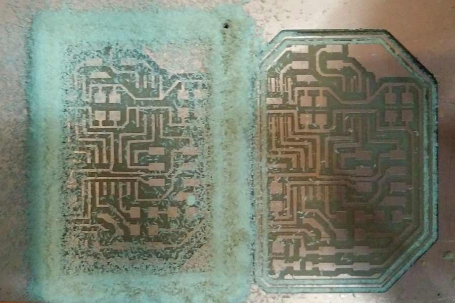
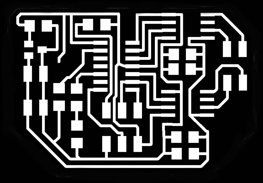
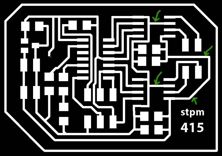
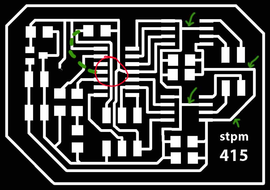
Before sending the file again I realized there were design mistakes on my board. I had omitted to connect the LSS pin of the H-bridges to the GND. I did the correction and reexported both trace and outline. The outline came out again as 2 lines in Fab Module so I eliminated the black part outside the outline on photoshop and that solved the problem. That helped me understand how does the Fab module actualy works: it mills a line at the exact spot where the white and the black meet on the board. Since I had framed the white frame with black it did mill a line on each side of the frame. That is important to understand when making the outline.
The pictures below shows the png of the original and the corrected board (corrected traces in green)
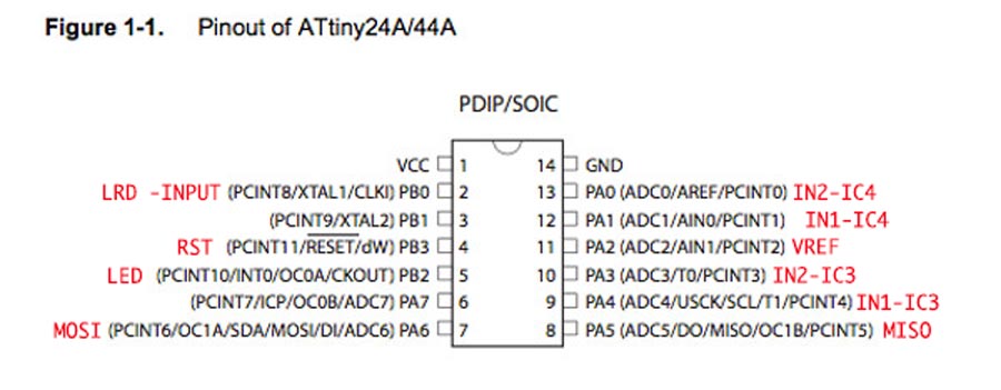
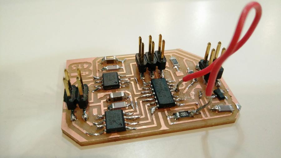
While milling the board I was discussing with a fellow students and realized that I had connected the light sensor to a PB pin ( a digital pin) of the Attiny which will not work to read the light variation. Because peripherals with relative readings must be connected to an analog pin. The sensor would read the light but will have no range. It will either be on or off. Nevertheless I decided I will bridge the sensor to pin P07 manually instead of rerouting in Eagle. Anyhow for this exercise I do not think I will have time to write the code to integrate the input.
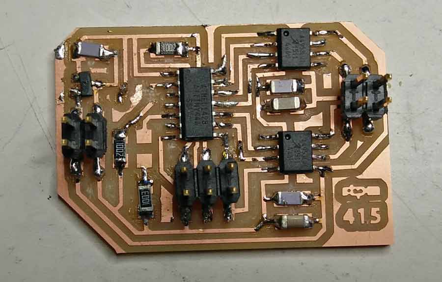
Stuffing the board
Stuffing the board went as usual. I learned to do it in the morning when my mind is fresh and there is not too much activity in the lab.
Testing the board
The board needs to be connected and programmed. I will load the C program from Neil using the Avrdude programmer which will be connected to the 6pin header (as in previous exercise). Differently from previous board this one needs to be powered from an external source - an Arduino board can do that job by connecting the 5V and GND to respectiv VCC and GND pin of the board.
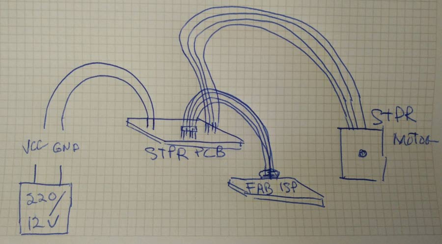
The Nema17 has 4 wire and I deduct it is of TYPE B. None of these cables carries direct current. If they get mixed up it won't create a short circuit. It would simply not make the motor move. If there is a confusion the way to deduct which cable goes with which simply try a combination and if the motor makes no resistance it means it is not the right pair. When connected the right pairt it should be difficult to move the motor shaft by hand - that is becaus ewhen the right pair is connected a magnetic field is active and creating a reistance/force.
The wiring diagram shows to connect theyellow with blue and red with green..

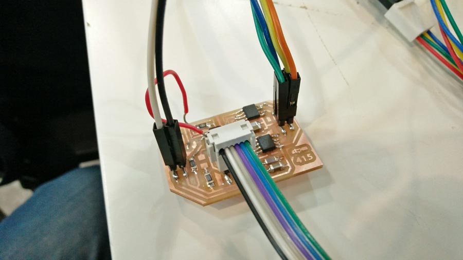
To program the board the stepper does not need to be connected but the board needs to be powered. This is easily done by connecting jumper cables from GND and 5v of a usb FTDI cable to the respectiv pins of the board (power 4 pin header). The USB tiny or a programmer connects to the 6 pin header and the make fle needs to be run.
The board connected to the AVRDUDE (green light) but it did not bootload (error message: "connection error"). I reviewed all the connections and finally realized I had made another mistake and omitted to trace the RST connection to the PIN03 of the Attiny. I made a bridge and that solved the problem.
Programming the board
I downloaded the C code and the make file (identified as "full" and "make file" in the fab academy page's stepper motor section and saved it in a new folder in my original file folder(desired folder)
Open the link in a browser page and save the file in the desktop's desired folder.
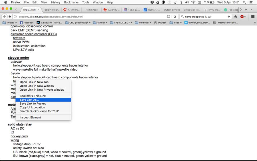
To execute these files, go to terminal, go to the directory (cd ~/desktop ... etc, etc up to where the files are saved.) Once in the directory type "ls" to see the content. That comfirms the .C and .make file are there.
I am documenting again the command line sequence to really get it into my workflow. It is still a little abstract for me.
The command to compile the c code from terminal:
sudo make -f hello.stepper.bipolar.44.full.make program-avrisp2
In this command line:
"sudo" is the user identifier (before executing terminal will ask the pw)
"make" is the command
"hello.stepper.bipolar.44.full.make" is the file
"avrisp2" is the programmer used to program the board
(note that the last part of the command is "avrisp2" because that is the command for the AVRDUDE that I am using as a programmer. If I would be using the FabIsp I would add "fabisp" instead.)
Terminal will compile the code, will program the Attiny with it and the code will be executed automatically.
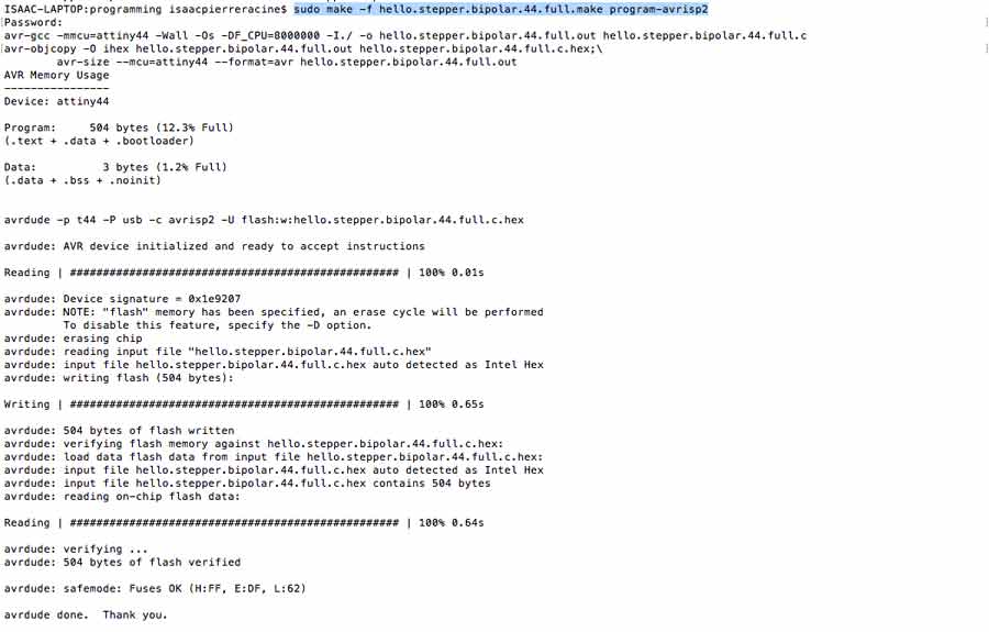
The motor should have started running but it did not. It compiled well and when I tried to run it the AVRDUDE blinked orange a few seconds and turned back green but the motor did not operate nor did I got an error mesaage. It took me a while to figure why but I did:
1º- I was trying to make a 12v motor operate with a 5v (arduino) source.
Connecting the board to a 12v source (oscilloscope in this case) made the motor started executing the programmed sequence.
I am not really happy with this board so I corrected the traces in photoshp, remilled and stuffed a new one. This time I added a led (and a 499k resistor) as a pilot showing the board is powered.
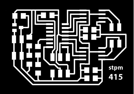
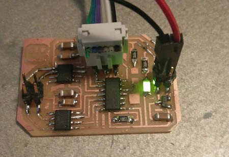
Now that I got Neil's code to run I played around to have the steppermotor to do different things. I started by simply have it to spin clockwise in an infinite loop. I commented the "for" operators section and added a simple an infinite loop
//infinite loop
while (1){
//spin clockwise
step_cw();
It worked well but after a while it started making noises and loosing steps. The problem do not look like it is a code issue but i continued making another variations to comfirm it. I set a maximum number of steps and added an "if and else" statement so the motor spins clockwise 50 steps and spin counterclockwise 50 more steps, than stops.
// "i" is the number of steps.
//if i is smaller than 100
while (i<100) {
//i is an increasing value
i++;
//if i is smaller than 50 spin clockwise
if (i<50)
step_cw();
//else spin counterclockwise
else
step_ccw();
}
The stepper responded well but when I started increasing the value of "i" it started to do odd things - started to go back and forth before completing the ccw spin. More I increased worst it would get.
I suspected the problem was from the electronics or the connections so I checked the connections of the boards, to the motors but it persisted. Finally I realized the motor I was using was unipolar. I repeated the tests with the bipolar motor and it started working perfectly well.
I went back to the code. I programmed an integrer "n", integrated a clockwise and counterclockwise function + an incremet of 50 steps every time it changes direction.
I inserted these functions before the main:
//spins n steps clockwise
void step_ncw(int n) {
int i=0;
while(i
step_cw();
}
}
//spins n steps counterclockwise
void step_nccw(int n) {
int i=0;
while(i
step_ccw();
}
}
In the main I declared the integrer "n" and created the loop:
// 1. n starts at 0
int n=0;
//repeat the following sequence for ever but incremet "n" by 50 each time
while (1){
n= n+50;
// spin n steps cw
step_ncw(n);
//spin n steps step_ccw
step_nccw(n);
}
I did not go very far in exploring the #define section of Neils code but I tried changing the numbers of PWM cycles and the number of steps. Descreasing the PWM and Step number (keeping th eproportion) made the motor spin faster.

Conclusion
It was a great learning week. I got valuable experience with every processes involve in this assignment . Getting more familiar with important issues - - from designing, to milling, stuffing and coding. C code is still a huge challenge but I am breaking the ice.
I also learned how important to be fully concentrated when working on electronic hardware. So many little details to take in consideation. . The slightest mistake can convert the process into a nightmare. It is natural to get into a loop when troubleshooting but keeping calm is the best way to find the solution which is often the most simple thing. I feel comfortable with Eagle now, with milling the pcb and soldering and the general workflow involved.
I am still very weak in programming but I feel I am starting to understand some basic concepts.
I was very ambitious to insert a led and a light sensor and think I will get to programm it. I had not even a second to get to it but the board is there ready for it when I have time.
