For this assignment I chose the stepper motor (bipolar).
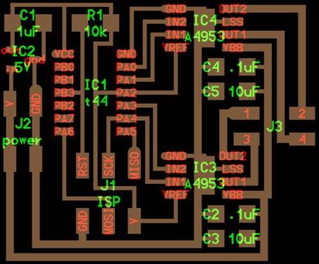
The circuit board uses 4 Integrated Circuits:
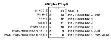
IC1: Microcontroller Attiny44
IC2: Power (voltage) regulator, limiting 5 V for Attiny44.
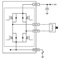
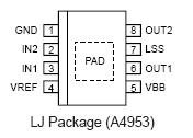
IC3 and IC: Mosfet bridge (to power the stepper motor)
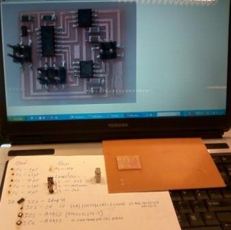
Work in progress, verifying circuit and selecting components.
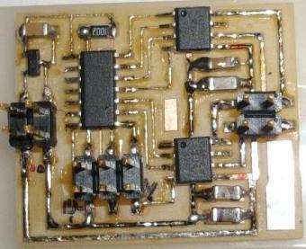
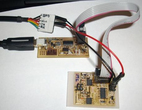
Assembled circuit board:
Programming the Circuit Board:
OS: Linux (UBUNTU 12.01)
Hardware:FabISP programmer and hello.stepper.bipolar circuit board and stepper motor (bipolar).
1º Copy the hello.stepper.bipolar.44.full.make and hello.stepper.bipolar.44.full.c files to Desktop;
2º Go to Ubuntu Terminal and move to Desktop;
3º Type: sudo make -f hello.stepper.bipolar.44.full.make program-usbtiny
Will be create more two files *.hex and *.out
This is the Terminal output produced:
estg@estg-A7C:~/Desktop$ sudo make -f hello.stepper.bipolar.44.full.make program-usbtiny
[sudo] password for estg:
avr-objcopy -O ihex hello.stepper.bipolar.44.full.out hello.stepper.bipolar.44.full.c.hex;\
avr-size --mcu=attiny44 --format=avr hello.stepper.bipolar.44.full.out
AVR Memory Usage
----------------
Device: attiny44
Program: 496 bytes (12.1% Full)
(.text + .data + .bootloader)
Data: 3 bytes (1.2% Full)
(.data + .bss + .noinit)
avrdude -p t44 -P usb -c usbtiny -U flash:w:hello.stepper.bipolar.44.full.c.hex
avrdude: AVR device initialized and ready to accept instructions
Reading | ################################################## | 100% 0.01s
avrdude: Device signature = 0x1e9207
avrdude: NOTE: FLASH memory has been specified, an erase cycle will be performed
To disable this feature, specify the -D option.
avrdude: erasing chip
avrdude: reading input file "hello.stepper.bipolar.44.full.c.hex"
avrdude: input file hello.stepper.bipolar.44.full.c.hex auto detected as Intel Hex
avrdude: writing flash (496 bytes):
Writing | ################################################## | 100% 0.27s
avrdude: 496 bytes of flash written
avrdude: verifying flash memory against hello.stepper.bipolar.44.full.c.hex:
avrdude: load data flash data from input file hello.stepper.bipolar.44.full.c.hex:
avrdude: input file hello.stepper.bipolar.44.full.c.hex auto detected as Intel Hex
avrdude: input file hello.stepper.bipolar.44.full.c.hex contains 496 bytes
avrdude: reading on-chip flash data:
Reading | ################################################## | 100% 0.14s
avrdude: verifying ...
avrdude: 496 bytes of flash verified
avrdude: safemode: Fuses OK
avrdude done. Thank you.
Then I used a Stepper Motor ref. 42BYGHM809 connected to the board, and innocently I used FTDI cable to power the circuit, obviously the stepper didn't rotate. The rated current of this stepper motor is 1.7 A.
I tried to measure the output signal of the header labelled J3 with oscilloscope, and didn't find "pulse" signals.
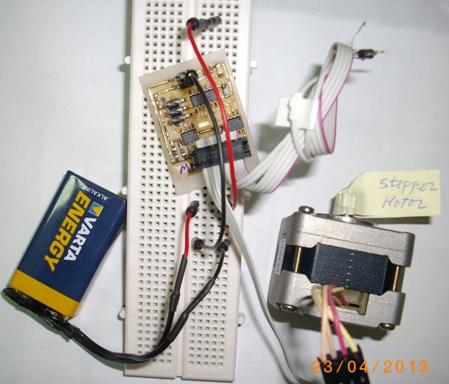
I was afraid to use greater voltages avoiding damage the microcontroller but the IC2 limits that voltage to 5V and 0.1 A, so, and thank you to some advices, I connected the circuit to a 9V battery. The video on the right side shows the output signals.
Then, I tried to find another stepper which requires less amperage and found a smaller stepper motor ref. STH-39D1126, bipolar, with the same 4 wires to connect.
Finally, I connected the stepper motor and it runs very well, like it's shown in this short flash video.
|