Assignment:
A_ Interface and application programming
A_write an application that interfaces with an input &/or output device that you made.
comparing as many tool options as possible
This week's assignment is a big challenge for me as programming is still my weakest point. But I'll get around to it and will start digging into it. Let start with the beginnig.
What is an interface?
An interface can be described as the mean to visualize datas from a computer program. It is in it-self a program that trasnforms datas into objects (visuals, sounds, etc.) that users can interact with.
I will do this assignment using the simplest application - Arduino/Processing. I will first do some simple exercices to understand and put in practice the workflow and relationship between the 2 applications and finally I will interface the datas from a board I created for my final project which has a potentiometer input and an output to a Neopixel led strip.
Depending on how far and fast I get to visulaize these datas I will try to create a similar interface using python.
I started with this Serial Communication with Processing tutorial which is very basic but helped to understand the workflow and relationship between Arduino IDE and Procssing. Both applications uses a similar language, syntax and logic. This compatibility makes it very easy to have them work together. While Arduino code is the program that is loaded onto the board the Processig code represents the instructions that translates the datas generated by the board into digital objects (sounds, images, interaction, etc).
In this first exercise I simply connected a push button to Arduino Analog port A4 and read the datas of the button beeing pushed using a simple Processing script in Java mode.
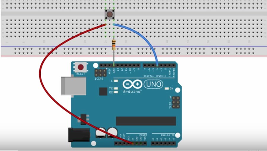
The Arduino script reads the datas from the push botton and digital write the datas through the serial communication port. To comfirm datas were sent to the communication port I replaced the "digitalwrite" lines by "digitalprint" and opened the serial monitor. When pressing the button the 0 are replaced by 1 which comfirms it.
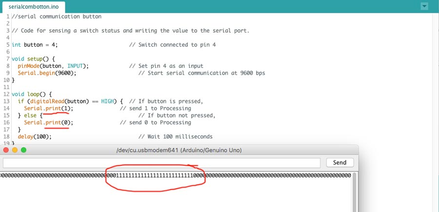
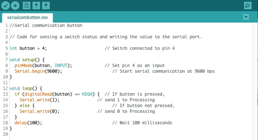
I re-edited the code back to "digital write".
The processing code is a little bit more complex but it obeys the same logic:
1º connect the sketch to a library (Import library), create an object from the serial class, create an integrer for the value read from the serial port
2º create a setup - set the interface window size and set the port to read the datas from serial communication port.
3º create a loop(draw) - create a visual object (a square within a window) that will interact with the datas read.
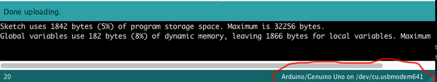
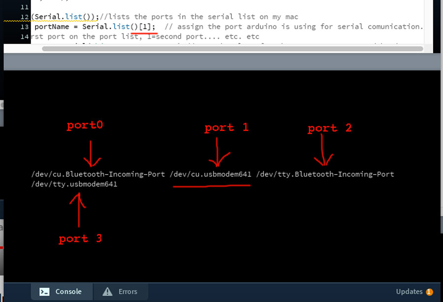
Note: In Arduino we define the serial communication port in the tool menu but in Processing we do it within the code directly and we need to define which port to use. The port to use is the port that Arduino uses for serial communication and which appears either on the tool menu or at the very bottom of the Arduino sketch:
In the setup of Processing we can add a line of code "println(Serial.list());" to list the ports that are available. Running the code shows the port in the bootom window. There are listed in an array mode which means the 1º =port 0, the 2º =port 1, etc. etc. The port Arduino uses corresponds to PORT 1 (which is the 2º on the list) and so I inserted the line of code "String portName = Serial.list()[1];" to define the port for processing to get the datas from.
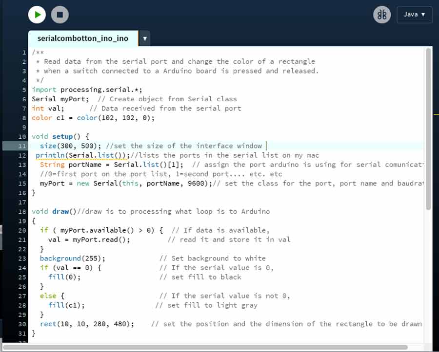
The following screenshot is the complete code with the function of each lines of code described. I edited the template of the example apapting the size of the window, of the square and the color (creating a variable in RGB color mode) - see this link for further documentation on color with Processing js.
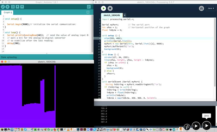
Next I made another exercise interfacing a graph with the datas collected from a light sensor connected to an Arduino board. The script visualize the values collected by the light sensor and map it into an X and Y position on a graph. I used a template and adapted some of the graphic aspects. The resistance I use is too high for the LRD sensor making the minimum never reaching O - not using potential range. With this exercise I used new Processing functions such xPos, SerialEvent and inByte.
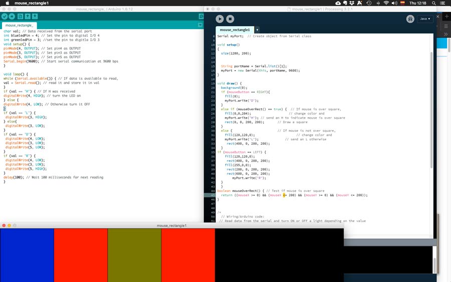
Next I created a sketch in Arduino and wired a board with 3 leds (Red, Blue and Green) and wrote a Processing program that makes colored squares in different position of the screen top interact with the mouse position and buttons (left and right).
1º- left mouse button pressed fill the frame with black + all leds are off
2º- a 200 x 200 px blue square pop up when mouse is over the right end side of the window (between 0 and 200 and no button pressed) + blue led turns on.
3º- when mouse is not over the blue square a green square popups at 600 px from the right end limit of the window and stays even if mouse scroll over + green led turns on
4º- when right mouse botton is pressed 2 red square popsup on each side of the green square which disappears + red led turns. This Processing- Interactivity page was very helpful to learn how to create this program.
The next exercise I connected a potentiometer on the Arduino board and downloaded a Processing program that slides a yellow circle from left to right as the potentiometer value increases. Here I introduce more complex functions and datatype such as float, maps and padding - some to do with the graphic aspect of the interface but others with the functonality.
Here the Arduino + processing program that I used as a start point.
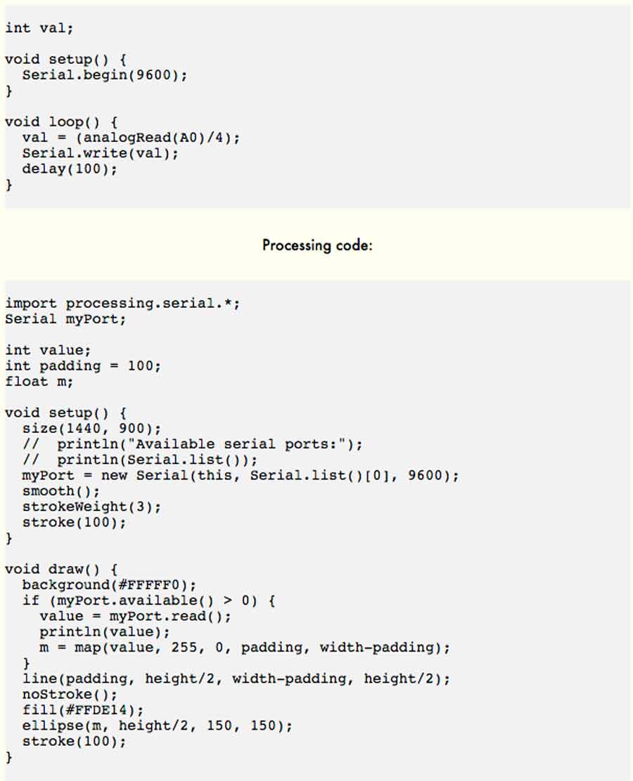
I wired the potentiometer to the Arduino board and ran the program as is but it took only 1/4 of potentiomemnter turn(90º) for the yellow circle to travel from one extreme to the other of the screen . The ball would go 4 times from one end to the other when turning the potentiometer knob 360º, and the value read by Processing would range between 0 and 255 also 4 times.
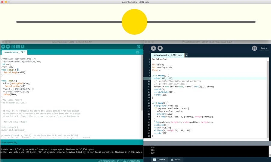
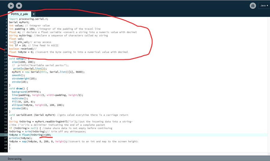
Bytes range from 0 to 255 as opposed to ASCII characters which range from o to 1023. For the yellow circle to travel only once from one side to the other when potentiometer is turned 360º the ASCII characters needs to be converted into strings (sequence) of bytes and map the bytes to a proportion where o-1023 is equivalent to 0-255). The program needs to be adapted so the conversion happens outside the "void draw" function by adding a "seria.event"function in which the string value in bytes is mapped.
I picked some bits of codes from different sources, and with my instructor managed to get the program to do what I was intneding. It's a bit of a patching and far from elegant but it worked.
The next and final step of this assignment is to make the same interface work on an Attiny84 board I made for my final project. The board has 3 Analog I/O pin but for this exercise I will use only one of the output pin - a potentiometer.
Arduino board comes by default with Serial communication library but when writing a serial communication sketch for Attiny board we need to tell the Arduino IDE to link it to a SoftwareSerial library. This is done by including and declaring the library in the first lines of code.
I had written a sketch to test my board through serial monitor and tryed to run it and send the datas to Processing but the yellow circle did not move along with the potentiometer. I double checked in Arduino serial monitor and comfirmed it was printing the value but Processing not only the circle would not move in Processing but there were no values coming in. After a little research I realized the values Arduino read from the potentiometer are printed as ASCII character and need to be be converted into Bytes for serial communication and for this to happen Arduino needs to "SerialWrite" instead of "SerialPrint" the datas.
Serial.write()
Writes binary data to the serial port.
Serial.print()
Prints data to the serial port as human-readable ASCII text.
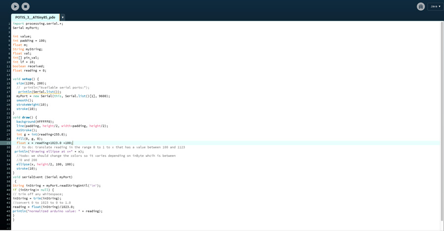
The rest of the Arduino Sketch is very simple and worked perfectly well. But I want ed to make a further itiration of the processing program but cleaining it up but also get the ball to change color as it slides from one end to the other.
Basically what I did is:
1º in the serial draw function
//create an integrer g which corresponds to the reading x 255
int g = int(reading*255.0);
//set the fill color as int g
fill(0, g, 0);
//define x as decimal numerical number which equal to: reading* decimal ASCII character +100 - 100 set the start position of the yellow circle equivalent to padding value.
float x = reading*1023.0 +100;
//translate reading in the range 0 to 1 to x that has a value between 100 and 1123.
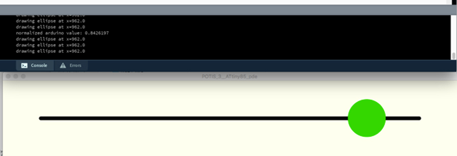
println("drawing ellipse at x=" + x);
2º in the serial event function:
//convert 0 to 1023 to 0 to 1.0
reading = float(inString)/1023.0;
// print in the processing monitor the value read by arduino
println("normalized arduino value: " + reading);
And finally I canceled the last line of code "reading = map(reading, 0, 255, 0, height);" map line of code as it is no longer necessary.
With thtis I managed to slick my code and get the yellow circle to change from black to bright green as it slides along the potentiometer, and have the Arduino reading printed on the Processing monitor.
Here a series of links and references I used and were very helpful:
Processign potentiometer
Processign potentiometer
Processign references
serial print arduino
Processing: serial data
graphing data from Arduino sensor
Connecting Arduino to processing- Handshake.
And other references about interfacing with Python which I did not have tome to explore:
Arduino Matlab
Pythn to plot graph of serial data from arduino Uno analog pin
Python to Arduino
Conclusion
This week I learned a lot but I will need a long time and lots of practice to assimilate all I goit acquainted to. Nevertheless it is a big step in getting more confident with actually writing programs. Unfoertunatly I git really involved with Processing and did not get around to try Python but I feel it was better to go deeper into one language than try scratching a few. The reason is simply that I think getting better at one will give the skills, knowledge and confidence to challenge more language in the future.
I am also very happy that this exercise will also serve my final project.