About Week 7
My Embedded Programming Exercise...
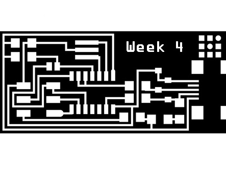
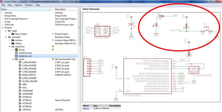
This week assignment was about Embedded Programming, in particular starting from my previous hello-world board:
- 1. Read the microcontroller data sheet.
- 2. Program it
In few words the essential capability to program a microcontroller is to know its ports & pins, its input/output (I/O) system and related functions. So by means of ATTINY44 datasheet I read its pins' codes, and related alternate functions:
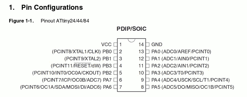
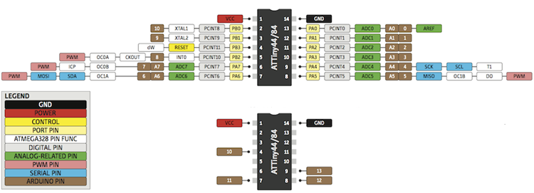
I found this useful image that provides a schematic summary of ATTINY44 pin
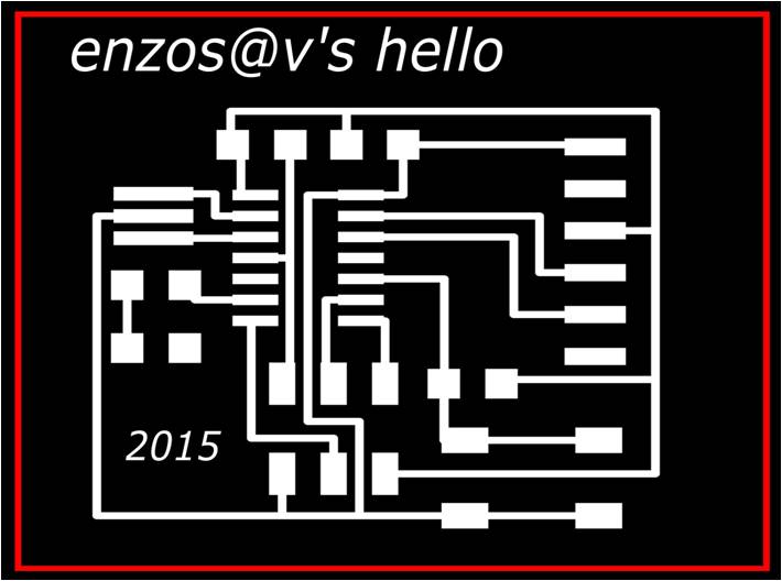
I went back on my hello board design and the Led, the button and related resistors were connected to ATTINY44, to pin 6 and 10 respectively,that is ports PA3 and PA7 respectively.

After this study, I started to check if my hello board was OK. To do this for the first try, first of all I studied from Fab Academy 2015 Tutorials the structure of Makefile:
PROJECT=hello.ftdi.44.echo
SOURCES=$(PROJECT).c
MMCU=attiny44
F_CPU = 20000000

CFLAGS=-mmcu=$(MMCU) -Wall -Os -DF_CPU=$(F_CPU)

$(PROJECT).hex: $(PROJECT).out
	avr-objcopy -O ihex $(PROJECT).out $(PROJECT).c.hex;\
	avr-size --mcu=$(MMCU) --format=avr $(PROJECT).out

$(PROJECT).out: $(SOURCES)
	avr-gcc $(CFLAGS) -I./ -o $(PROJECT).out $(SOURCES)
Where the first four lines are configuration declaration of the Makefile:
- Name of the file to compile
- Extension of the file to compile
- Microcontroller to program
- Frequency of the board to program
After this I downloaded and used a led blink C program from Massimo Menichinelli's by using my FabISP:
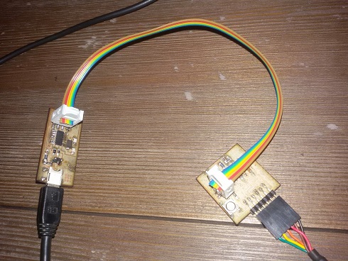
The two board were recognized by my PC so I used Win-GCC for the following commands:
D:\FabAcademy_Files\Embedded_Programming\steadyled>make
avr-objcopy -O ihex steadyled.out steadyled.c.hex;\
        avr-size --mcu=attiny44 --format=avr steadyled.out
AVR Memory Usage
----------------
Device: attiny44

Program:     172 bytes (4.2% Full)
(.text + .data + .bootloader)

Data:          0 bytes (0.0% Full)
(.data + .bss + .noinit)


D:\FabAcademy_Files\Embedded_Programming\steadyled>make program-usbtiny-fuses
avr-objcopy -O ihex steadyled.out steadyled.c.hex;\
        avr-size --mcu=attiny44 --format=avr steadyled.out
AVR Memory Usage
----------------
Device: attiny44

Program:     172 bytes (4.2% Full)
(.text + .data + .bootloader)

Data:          0 bytes (0.0% Full)
(.data + .bss + .noinit)


avrdude -p t44 -P usb -c usbtiny -U lfuse:w:0x5E:m

avrdude: AVR device initialized and ready to accept instructions

Reading | ################################################## | 100% 0.01s

avrdude: Device signature = 0x1e9207
avrdude: reading input file "0x5E"
avrdude: writing lfuse (1 bytes):

Writing | ################################################## | 100% 0.01s

avrdude: 1 bytes of lfuse written
avrdude: verifying lfuse memory against 0x5E:
avrdude: load data lfuse data from input file 0x5E:
avrdude: input file 0x5E contains 1 bytes
avrdude: reading on-chip lfuse data:

Reading | ################################################## | 100% 0.00s

avrdude: verifying ...
avrdude: 1 bytes of lfuse verified

avrdude: safemode: Fuses OK

avrdude done.  Thank you.


D:\FabAcademy_Files\Embedded_Programming\steadyled>make program-usbtiny
avr-objcopy -O ihex steadyled.out steadyled.c.hex;\
        avr-size --mcu=attiny44 --format=avr steadyled.out
AVR Memory Usage
----------------
Device: attiny44

Program:     172 bytes (4.2% Full)
(.text + .data + .bootloader)

Data:          0 bytes (0.0% Full)
(.data + .bss + .noinit)


avrdude -p t44 -P usb -c usbtiny -U flash:w:steadyled.c.hex

avrdude: AVR device initialized and ready to accept instructions

Reading | ################################################## | 100% 0.02s

avrdude: Device signature = 0x1e9207
avrdude: NOTE: FLASH memory has been specified, an erase cycle will be performed
         To disable this feature, specify the -D option.
avrdude: erasing chip
avrdude: reading input file "steadyled.c.hex"
avrdude: input file steadyled.c.hex auto detected as Intel Hex
avrdude: writing flash (172 bytes):

Writing | ################################################## | 100% 0.23s


avrdude: 172 bytes of flash written
avrdude: verifying flash memory against steadyled.c.hex:
avrdude: load data flash data from input file steadyled.c.hex:
avrdude: input file steadyled.c.hex auto detected as Intel Hex
avrdude: input file steadyled.c.hex contains 172 bytes
avrdude: reading on-chip flash data:

Reading | ################################################## | 100% 0.16s


avrdude: verifying ...
avrdude: 172 bytes of flash verified

avrdude: safemode: Fuses OK

avrdude done.  Thank you.


D:\FabAcademy_Files\Embedded_Programming\steadyled>
All went well and my hello board started to blink.
Then I removed FabISP-hello board connection and I checked the program loaded that is a led switch on-off once button pressed:OK!

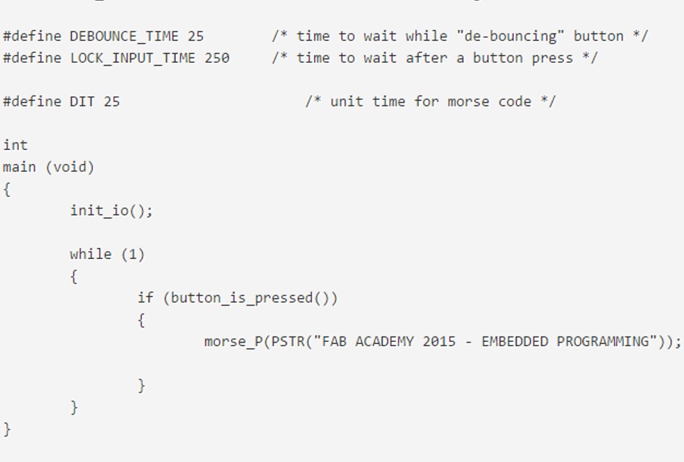
Once verified my board I started to create a new program to load. My first idea was to create a Morse Code translator that translates a string into Morse code by means of led blinking. To do this I started from the previous led blink, removed the unused functions and inserted two functions for the elaboration of a String by calling for each character morse_char decode function. My first try was to put in memory a string ('FAB ACADEMY'-> ..-. .- -... / .- -.-. .- -.. . -- -.--) and in while(1){} block in the main the instruction to start the blink Morse Code once the button is pressed:
#include#include #include #include void delay_ms(uint16_t ms); void init_io(); int button_is_pressed(); void morse_character(char c); void morse_P(const char *s); const unsigned char morse_code_table[]; #define F_CPU 20000000UL /* 20MHz crystal oscillator */ #define BUTTON_PORT PORTA /* PORTx - register for button output */ #define BUTTON_PIN PINA /* PINx - register for button input */ #define BUTTON_BIT PA3 /* bit for button input/output */ #define LED_PORT PORTA /* PORTx - register for LED output */ #define LED_BIT PA7 /* bit for button input/output */ #define LED_DDR DDRA /* LED data direction register */ #define DEBOUNCE_TIME 25 /* time to wait while "de-bouncing" button */ #define LOCK_INPUT_TIME 250 /* time to wait after a button press */ #define DIT 25 /* unit time for morse code */ int main (void) { init_io(); while (1) { if (button_is_pressed()) { morse_P(PSTR("FAB ACADEMY")); } } } void delay_ms(uint16_t ms) { while ( ms ) { _delay_ms(1); ms--; } } void init_io() { /* set LED pin as digital output */ LED_DDR = _BV (LED_BIT); /* led is OFF initially (set pin high) */ LED_PORT |= _BV(LED_BIT); /* turn on internal pull-up resistor for the switch */ BUTTON_PORT |= _BV(BUTTON_BIT); } int button_is_pressed() { /* the button is pressed when BUTTON_BIT is clear */ if (bit_is_clear(BUTTON_PIN, BUTTON_BIT)) { delay_ms(DEBOUNCE_TIME); if (bit_is_clear(BUTTON_PIN, BUTTON_BIT)) return 1; } return 0; } // blink a single character in Morse code void morse_character(char c) { unsigned char code, count; if (c == ' ') { delay_ms(DIT * 7); return; } if(c >= 'A' && c <= 'Z') { code = pgm_read_byte(morse_code_table + (c - 'A')); } else { return; } for (count = code & 0x07; count > 0; count--) { LED_PORT=0b00000001; if (code & 0x80) { delay_ms(DIT * 3); } else { delay_ms(DIT); } LED_PORT=0b10000000; delay_ms(DIT); code = code << 1; } delay_ms(DIT * 2); } // blink an entire message in Morse code // the string must be in flash memory (using PSTR macro) void morse_P(const char *s) { char c; while (1) { c = pgm_read_byte(s++); if (!c) break; morse_character(c); } } const unsigned char PROGMEM morse_code_table[] = { 0x40 + 2, // A: .- 0x80 + 4, // B: -... 0xA0 + 4, // C: -.-. 0x80 + 3, // D: -.. 0x00 + 1, // E: . 0x20 + 4, // F: ..-. 0xC0 + 3, // G: --. 0x00 + 4, // H: .... 0x00 + 2, // I: .. 0x70 + 4, // J: .--- 0xA0 + 3, // K: -.- 0x40 + 4, // L: .-.. 0xC0 + 2, // M: -- 0x80 + 2, // N: -. 0xE0 + 3, // O: --- 0x60 + 4, // P: .--. 0xD0 + 4, // Q: --.- 0x40 + 3, // R: .-. 0x00 + 3, // S: ... 0x80 + 1, // T: - 0x20 + 3, // U: ..- 0x10 + 4, // V: ...- 0x60 + 3, // W: .-- 0x90 + 4, // X: -..- 0xB0 + 4, // Y: -.-- 0xC0 + 4 // Z: --.. };
Download the code