Input Devices Class
10th Worldwide gathering for Fabacademy 2015 feat. prof. Neil Gershenfeld
8 April
9 weeks to Final project
Class
Sense your surroundings: from the physical environment to digital data
Here is when things start got more exiting to me. Having the possibility of interacting life actions with electronics. The world of sensors!
INPUTS - More relevant Sensor Boards:
- Step-Response
- Compass
- Magnetic Field - hall effector
- Vibration - DC motor
- unipolar stepper
- Distance - sonar
- acceleration, orientation, rotation
- sound - piezo
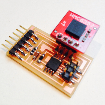
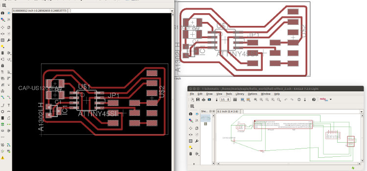
For this weeks assignment I therefore chose to experiment first with the Hall effect sensor as it seamed easy to start with. I first start redesigning it in Eagle so that I could get more comfortable with the software. Unfortunately I was so focused on redesigning Niel's Hall effect board as small has I could so it wouldn't be unconfortable to wear, I forgot a few connections. That obviously reflected later while trying to program - -rc ERROR .
So had to go back to data sheet...attiny45
I rapidly confirmed the more obvious was connecting the Attiny45 to GND and another was switching around position of 2 pins. A bit unsatisfied with shape or flying cables I tried out another approach.
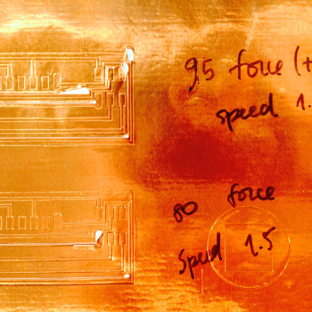
To make it a bit more challenging and useful to my final project I figured that if my goal was a wearable device that should feel as comfortable as possible to the skin I should try to make Flexible circuits. So redesign it in Kokopelli to fit my harm length and then cut it on Copper sheet in the vinyl cutter.
The design part went smoothly.


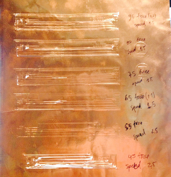
I did the traces a bit thicker then in the regular PCBs for better float of current and adhesion but still and unfortunately the results were not the best.
Tried several settings:
- Force 45 velocity 2.5
- Force 55 velocity 2.5
- Force 65 velocity 1.5
- Force 75 velocity 1.5
All failures non of them was able to cut all or through and through or at once. Or in other cases it wouldn't cut at all
A bit frustrated with the results I tweaked the design to thickness 23 and tried another roll of settings.
- Force 80 velocity 1.5
- Force 95 velocity 1.5
Another fail. At this point I had lowered the blade on the machine a bit and manually changed the cut power on the machine but still the results were not good. Started doubting about the quality and state of the cooper sheet. And moved on to the next try.
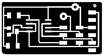
When back to Eagle and did a 2nd design for the same board and this time proper size and no fancy design wires. During the time I was doing the previous boards I researched on inputs and outputs and decided since I was doing a new one I could leave space for adding a piezo flat in the future so I did. Nevertheless for the first stage of testing I just redesigned, milled and stuffed the new board and test it out with the python script provided by Prof. Niel.

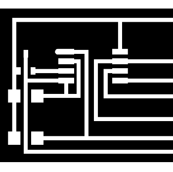
Hall effect sensor traces 18

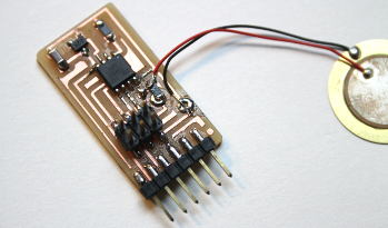
Final Hall effect
In this video the Board is already milled, stuffed and connected to an FTDI cable previously programed with fabISP with the code provided in class page. To enable the python code you have know which USB port your device is connected so there was the need of double checking using ls /dev/tty* that will show you in terminal to list of all USB ports available and the one it is in use. Typing the following in terminal will have things runing for you.
python hello.mag.45.py /dev/ttyUSB0
Later it will open the serial monitor graphics created in Python and then we are able to visualize the effect of the approaching magnet and it's different behaviors according to the two polarities and force created by different distances
What I learned from this:
- you should never be to greedy with space in a PCB that you produce and mill yourself. Tiny spaces are difficult to place the components and traces might get to close together and create involuntary merges during milling.
- the same applies for traces once you move from regular PCB copper boards to copper sheets an overall improvement has to be done to the design - in the vinyl cutter the design generally needs to be scaled and traces need to be thicker
- there is still a lot to learn - further readings where mandatory since I knew nothing before this class about serial communication, Baud Rates, Analog vs Digital, and among oher things it's urgent learning more about Python
- The is not enough time to learn C previously to this classes so if I knew that I would have taken more tutorials before Fab Academy
Note: Every code used on this test were the ones provided in class so they will not be added to available files in the bottom of this page
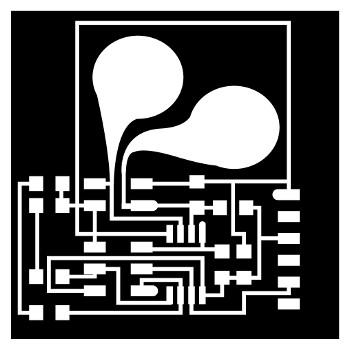
Final Step Response Board
At this moment felt better going back to Kokopelli to avoid unnecessary mistakes because time is running out for this week with all extra research and trying out different designs milling materials etc.
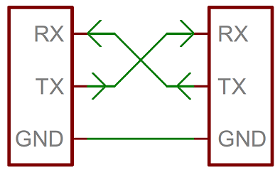
So redesigned it based on Prof. Niel's designs and a fellow student from last year Scott Zittek - input devices. Had more research done on how the TX RX communication works so that I could understand what we were performing while providing current flow with our fingers.
Ended up following Scoot's example and adding LED to monitor the behavior of the touch action code for this assignment since at the moment I know nothing about python a direct visual feedback from the board is more coherent to knowledge status. So I ended up adopting Scot's C code improvement for completing this assignment.
Analyzing the results I feel the signal from the two LEDs should be clearer and it remains a bit intermittent. Nevertheless is working and I learned a lot from this week so I am definately happy with the results.
Compass
In the end of the week I was advised by Francisco to leave this last board to deal up with later since meanwhile I could get profounder understanding of the dynamics of serial communications and use it further on Fab Academy
Also I had done this board without holes so, and since the pins should been loading any weight I might have to readdressed later for improving its layout
So at this point I only have this board milled and stuffed no testings were done yet