1. Project Proposal
Why?
How does our body perceive space? With physical and virtual space being over saturated with mass media and its overlapping images and over the top visual stimuli, will we still be able to navigate and understand our surroundings? What happens if we can no longer trust our eyes?
I began my studies on architecture because the understanding of space as an embodied sensorial experience was something that always intrigued me. And so I followed my personal research on how can that, in fact, build up our own sense of scale, motion and even our own sense of self, shaping an individual and his surroundings in time.
How do we construct our haptic memories? How do we understand space? How can built space enable social interaction? And how does it is ultimately involved in the construction of individual and collective identity?
These are some of the questions and topics around which I wish to direct my final project researches to.

Learning from las Vegas, Venturi/Brown
What and for Whom?
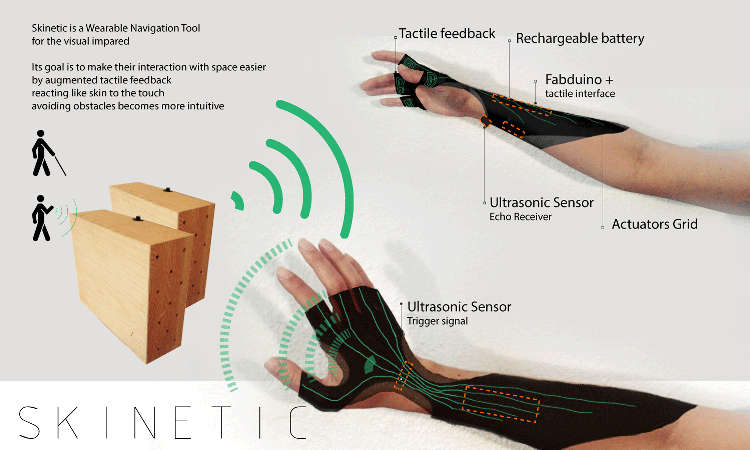
Targeting mainly the visual impaired people I wanted to build a wearable device for hands and torso that like a second skin, via augmented tactile stimulation, would enable the user to navigate space freely without the help of any white cane.
Like the M.I.T.s own Finger Reader this devise would be easily transportable and would have small volume so that it could be wearable under regular clothing.
What's new?
even if the main target public would be visual impaired people I would like to extend the possibilities of this devise by exploring the haptic space has a fully body experience. Meaning it could also help sighted people to navigate for example by GPS coordinates without having to hold any phone or tablet enabling them to fully enjoy their walk or traveling without always be looking at a screen instead of real life.
What I want to improve from other similar ideas already done is to bring to this kind of gadget the idea of extended surface skin, and that said create a set of outputs that could emulate directional fluxes, like the feeling of wind or waves in our body, directing our way naturally.

How?
Its base structure would be 3d printed in a flexible filament and it would have mounted sensors connected by integrated circuits that upon receiving the input from the surrounding environment would be able to translate that into output augmented vibrations, sounds or pressure.
The user will have to adapt to the signals so that he can react in advance to each barrier like stairs, walls, other people, etc.
In a more detailed phase I would like to be able to replicate a surface feeling by distance measuring from target to hand/fingers so that it could be more precise and also could do some studies on space/shape memory.
similar form / function studies

VIA (Visual Impairment Aid) by Patrick S
- Possible Electronics
- sensors of distance, ultrasonic
- GPS & Blue-tooth connected
- output pressure, vibration or sound mechanisms
- Arduino or similar board
- batteries
- Wire, electrical tape, and soldering materials.
- etc...
- Physical parts
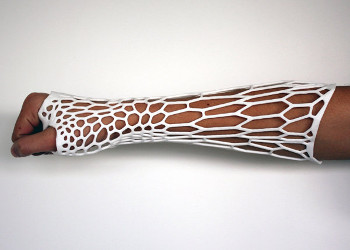
The final skin should be divided by little cells that clip on and rotate in an organic manner and not be in one piece like the casts in the upper pictures because I intend to give the user maximum mobility of the limbs.
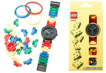
Also this could be a way of achieving different sizes of cells that could be clipped on and off (like the LEGO watch bracelet to the right) according to desired functions. Meaning, part of the cells would be structure and the rest of them programmable boards, being those the ones the user could interchange.
At the same time as the structure will be malleable some studies of volume for 3d printers should be taken in account, such as the ones by nervous system
3d printed cast J.Evil
2. Project Research Material
For better understanding of what I was trying to build I began gathering information organizing it in the shape of a blog page one which you can check following this link to the right or the upper tab for FABDAILY and searching for the posts under "Final Project" title.
/////// while PLUGGED-IN on FAB DAILY//////
3. Project Development
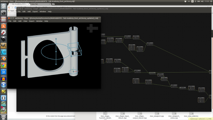
Design for 3D Print experiment - Antimony for Final Project
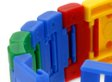
Lego swatch bracelet clip/off parts
On going task:
The main idea will be to 3d print a cell/part of my final project programmable skin
still don't feel very comfortable with scripting in Antimony so I might go revisit Grasshopper for better control of the shape.
This piece is a bit tricky to print due to its thin parts and overhanging areas, so also for that needs some redesign.file Download
This shape was a possible cell form, but still don't think I am very happy with the result as this presented here was more of a consequence of subtractive actions in Antimony as in form-finding, more than actual planed stable design. So I guess that will be next.
Has my biggest weakness is programming I decided to start with electronics.
First Steps
Spiral development: starting from basic
- First electronics
- Input: Sonar sensor - HC SR04 DATA SHEET
- Output: LCD Display + Piezo Buzzer, DC-motor
- start connecting arduino to input devices and output devices
- Arduino IDE programming
- Write code
- Test Code
- Document findings
Decided to use the FabKit version by fellow colleague Alejandro Escario[+] that came out during Inputs week I've been wanting to build my own Fabduino since electronics production week, so I did right after because I knew it would come on handy for my final project test phase. At this moment I didn't change anything about his design because I new little about what was "under the hood" but soon realized it would need male to female pins upgrade, so added them for all peripheral pins so it would be easy to test on breadboard for initial schematic connections.
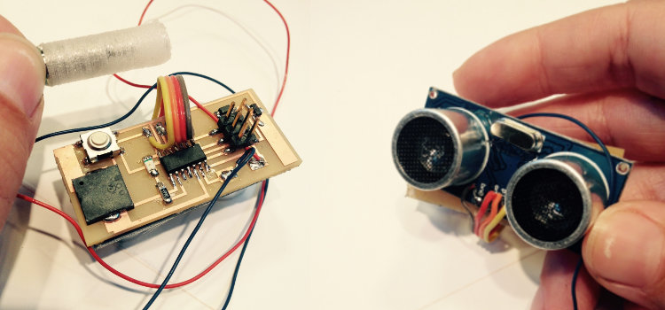
first started testing the sonar together with the display and battery to figure out if distances where accurate while on the move
then added the Piezzo as second output to define redline distances - when too close to a obstacle, sudden shift like stairs, gaps on the floor, etc. it would buzz.
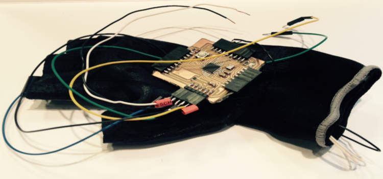
Once the mock up was working more or less I temporarily attached the board and mini breadboard with double sided tape to a ready made fabric glove and started to place the wires on the equivalent fabduino pins and around my hand.
The result was a big and proper rats nest. Everything was holding but the amount of wires flying around my hand, the huge size of the board and the difficult placing of the sonar sensor on the bottom of the forearm all together was asking for a different approach
But at this point it was Final Proposal presentation day, the day to get Prof. Neils approval and suggestions so that I was given the o.k. to move on. I had to accelerate the process by building a presentation board so that the overall idea was easier to grasp visually. Here is the board and short clip of the online presentation on the 27th of May
first prototype distance test
Happy to get an o.k. from Professor Niel but had to do some improvements according to his comments on the proper size dc motors actuators and the state of current wiring.
After class we placed our orders on Digykey website. Personally I asked for 2x flat surface Mounted piezzos (5v) and 5 tiny coin sized vibrating motors to use as outputs.
Unfortunately only the Piezos got here in time the tiny DC motors would only come around the 4th of July, what would be obviously too late. The motors I ended up using were recycled from another device for question of time this was the best choice available even without it's precious data sheet.
Improvements after proposal presentation:
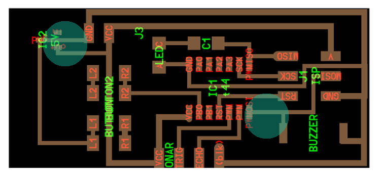
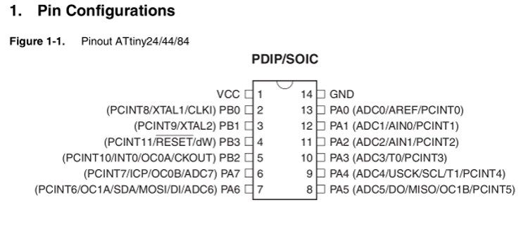
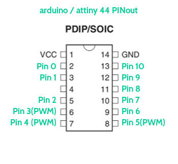
As in the end I was only using a part of the pins available in the Escario's Fabkit and for what I was creating I didn't need such a big microcontroller as the Atmega328p here used, I decided that all the electronics should be redesigned in order to fit on the back of the sonar sensor so the hardware area could shrink minimum possible and that the same logic should be applied to the chosen microcontroller capacity. So I ended up concluding an Attiny44 was powerful enough and just the right size.
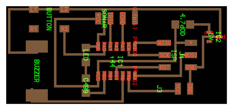
-Board Design and Production
For this small design, even if the components are not that many wiring could be a bit tricky regarding the size of the board and a few other constrains:
- reduced total area for board design
- only 4 PWM pins available 2 of which are MISO and MOSI
- sonar pins (Ground, Echo, Trigger and VCC) position shouldn't be changed
- Attiny should be in central position
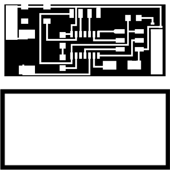
Taking these into consideration for the redesign I went [Retro] as in Kokopelli Retro style. Did the first version of the designs of a double sided board. After exporting .png from kokopelli at 50 px/mm you get a proper sized image for traces as well as cut board lines. With the Roland modela MDX-20 milling machine via fabmodules interface is easy to have good results just with default settings. So after a rightly aligned double sided board being placed over the sacrificial layer I got things running at a good pace.
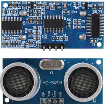
Sonar Sensor - model HC - SR04
The board was milled and components were placed but by the time I got to programming it I got a -rc ERROR and de voltage regulator was not reacting well to smoke test. Realized I had to add up a diode so that current was directed properly which I did but then the ERROR was recurrent. Then the second error became evident. The buzzer probably couldn't be connected to the MOSI pin. Concluded that new board had to be milled because having a two sided board on this case was causing me more difficulties to put everything together not to speak of having to remove the ISP connector to be able to flip the board on it's back so that it was facing the back of the sonar and the button was the only interaction device accessible. Not a good design!
First Skinetic Board Design
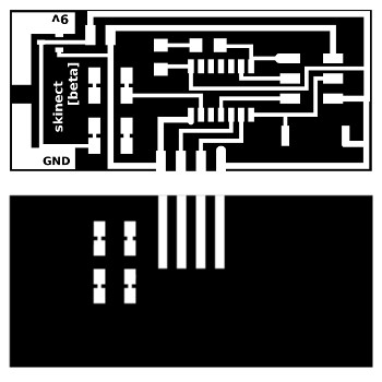
First Skinetic Board Traces

First Skinetic Board holes
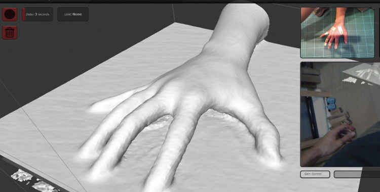
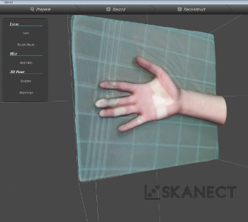
3D Scan
I had previously scanned my hands and arms together with Anders so that while designing I could use the generated mesh surface to exactly fit my wrist making the final piece feel as much comfortable as possible.
For the actual scanning we used Skanect with a Kinectic 3D scanner.
Relevant settings were:
- volume area was set low - 40x40x40cm bounding box
- lighting the scene - very important for optimal results
- fingers have to be very still - we found that best results came from taped or marked fingers
- very firm position - we ended up doing my scan in two parts both with the hand touching the table because outcomes were always a bit blurry if done otherwise
For final finishes of the mesh
- water tight for closing first edges
- closed hull for best results
- export as .OBJ
- Note: if your machine is not very powerful it might be a good idea to reduce number of mesh faces before saving to get a lighter file you can later edit easily
Design case holder for electronics + DC motor cylindric holder
Meanwhile I started designing the 3D model to use as holder for the electronics.
I went to Rhinoceros 5.0, since that's the one I am more efficient on, and I started to design a custom fit case that would, to one side, should be perfect fit to my arm and to the other, would be a case for holding the sensor in the right angle . Where I could slide in the electronics needed (my own design board + sonar + battery wire connector and mini DC motor)
The fittings of the DC motor case where to loose for the first time so I went for 6.4mm diameter it got perfect fitting with 1mm wall thickness.
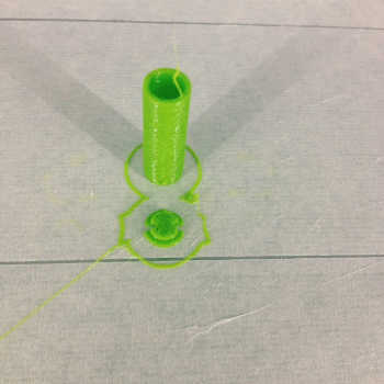
3D Design NURBS with RHINO of holder and DC motor enclosure
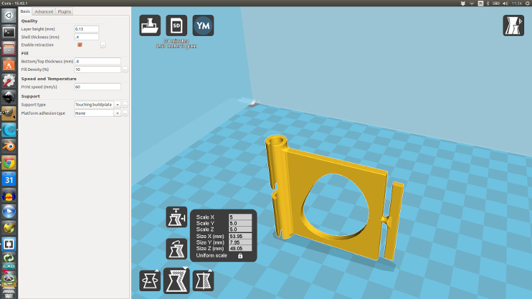
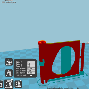
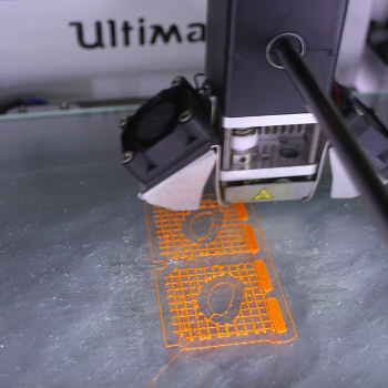
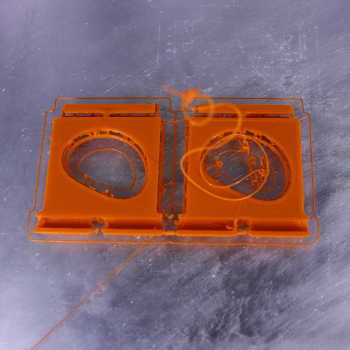
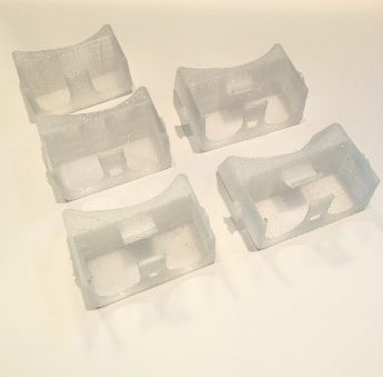
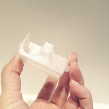
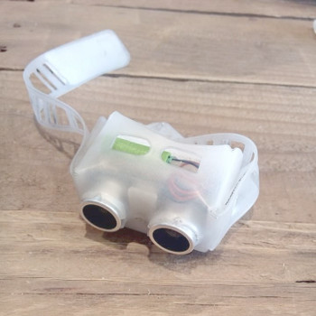
3D Print case holder
The initial didn't have 3D printed parts included as main parts. The fist idea was to get a mold done and cast a silicone flexible case out of it but as I was running out of time the first prototype came out 3D printed.
For that I used Cura 15.02.1 as a Slicer software to get the G-code and later on print that in our Ultimaker 2 in transparent PLA. These were the used settings:
- layer height = 0.2mm
- shell thickness = 0.8mm
- retraction = enabled
- botom/top thickness = 0.6mm
- Fill density = 20% (although it can be done with higher shell thickness and no infill)
- Speed and temperature = Default for this machine
- Support = none
Basic Settings
- Quality = Default
- Speed = (50;20;50;20;30;60 - by order)
Advanced Settings
- PLA temperature 240/250 - changes grade of transparency as well
- Flow = 115%
Extra settings tweaked on the printer
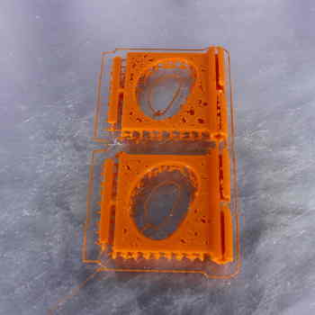
Several iterations add to be done in order to get the best fit:
- The first one printed was just a box with two openings for the sonar, no top to slide it in and a fit to the area of the arm mesh I've selected to place it on. The sonar was fitting but a bit tight, the part in contact with the arm was fitting very well but I had no way of holding it together yet, so went for second iteration
- On the second iteration was scalled by 2.5% to get a better fit for the sonar, extra holes were added for the power cables to come through on the sides as well as two extrusions that would help holding the laser cut arm band. An opening for a on of button was also added.
- Third iteration as an extra holder that gets the electronics pressed and better fit and it is located on top so that the dc motor is in closer contact with the skin.
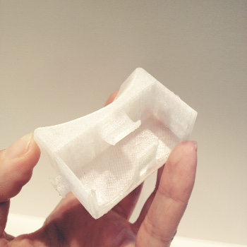
- In forth version the extrusions on the sides were made longer so that the folding overlapping layers are all fixed together with no need for glues. As the last version was ok I made two of them for showcasing.
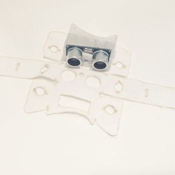
The following step was to build up a part to hold this firmly against the skin so I came up with the following design to cover the 3D printed case.
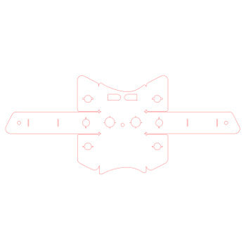
Laser cutting soft skin case holder - Full Spectrum 5G 45W Laser cutter
several iterations add to be done in order to get the best fit
"Less is more"
testing materials for soft tech (arm/hand piece):
NEOPRENE FABRIC 4.0mm
lasercut settings
- SPEED 30 POWER 2 - Good for engraving, far from cutting (settings by Trotect - clearly don't apply to our laser)
- SPEED 15 POWER 10 - Cut trough the first layer of fabric and half way of the interior
- SPEED 60 POWER 25 - Cut bit deeper did not get to the last fabric layer
- SPEED 40 POWER 30 - Cut everything but the fabrics surface are burned
Although the material was firm and ideal for holding on the rest or the parts I needed, the neoprene didn't feel like the right choice for several reasons, namely:
- Strong smell after cutting was not pleasant at all
- Would become to hot to wear directly on your skin even with several openings by design
- Sweat would cause discomfort in the long run
- As I was aiming for a subtle look that could feel like skin at this point this was pushing everything too far off the target
- expensive and difficult to find in stores, since it is only available in certain seasons
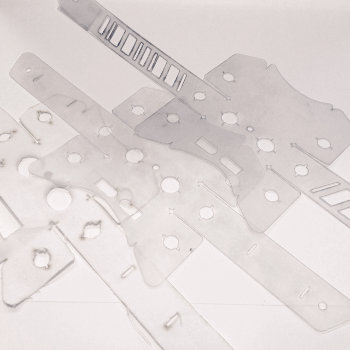
For those reasons I had to find another alternative. Luckily I came across this Food Safe Silicone Rubber sold by the meter. It was not expensive, it looked safe to be in contact with the skin and It ended up being no so difficult to cut and more importantly washable and odorless.
SILICONE FOOD SAFE RUBBER 1.5mm
lasercut settings
- SPEED 40 POWER 35 half way cut
- SPEED 35 POWER 35 almost
- SPEED 30 POWER 35 cut done!
The silicon rubber parts when cut leave a black powder where the laser cut through. As this material is translucent it needs to be washed or dipped in soap water for a while to be clean and ready to wear otherwise will just look dirty. At this point these parts where good to go at the moment although I am at not 100% happy with the result regarding the final look i was hopping for. I guess it is in fact a "never ending process" - new iterations on the way!
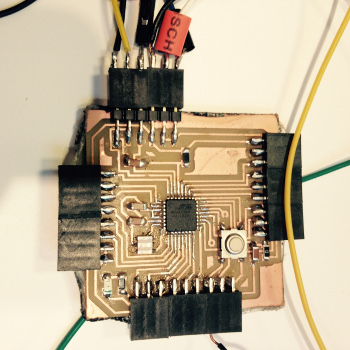
Back to electronics - Redesign
Again found myself on kokopelli grounds. Flipped the design around so that no longer was a double sided board and started displacing the wrong wiring to the correct positions.
- Added a LED for debugging purposes
- Moved the buzzer to the bottom and button up
- Sonar trigger to PIN 9 - on arduino (PA1 on attiny44)
- Sonar echo to PIN 7 - on arduino (PA3 on attiny44)
- Buzzer to PIN 2 - on arduino (PA3 on attiny44)
- Motor to PIN 3 - on arduino (PB2 on attiny44)
- Led to PIN 0 - on arduino (PB0 on attiny44)
But when you are tired everything gets more difficult and the mistakes start to pile up... it was only later that I found out, with a few hours of failure and researches, that the PINS that I was sacredly saving for some components didn't necessarily needed to be PWM by default and that I could generate Pulse Width Modulation by code.
At this point time was getting the best out of me and sucking a lot of my energy on traveling from Barcelona to Sitges back and forth to the lab so I decided to camp at there for the night. Inflatable mattress in and a few hours later I was back milling and stuffing a new board.
At this point of stress there are a lot of pictures that should be taken of the process and are unfortunately missing because it's "all hands on deck" and the last thing on your mind is taking a pause and a picture. Big mistake!
You should be taking several pauses and several pictures.
Back to programming - Arduino IDE
After the modular board was assembled the one unit sonar kit sensor was ready to be programmed.
Now that I was using a attiny 44 and not a fully compatible pin set like the Arduino comercial boards with the 328p Attmega, the approach was a bit different. So at first I thought it would be best to code in pure C code. For that I looked for somebody that had done something similar so I could have a case study to learn from I found this example from electronut for sonar sensor all done in c code so I extracted a bit of knowledge and calculated the time and best direction to follow if pure c code or library based platform Arduino IDE. The C code was a bit extensive and it took me a while to fully figure out every step of the code but it was worth it because that way I learned that pwm can be generated just by code and that enables you to be free from the constrains of just using the few pwm pins on the attiny44.
Nevertheless the Arduino IDE seemed to me to be the clearer approach for now and time wise a better choice for a beginner although I really like C code for it's lower level writing.
In Arduino and with help from Francisco I started of with just the sonar sensor as input and led as output for monitoring when at certain distance it became a dangerous area for a blind person. A few distances tests were done and it was working ok with led lighting up at a foot distance. The next step was preparing another pin to output a buzz tone so that it could be understandable for the visual impaired and that, for the time being, I could show it working for presentation day since vibrating motor wouldn't be that readable through web conference.
Testing 1st Prototype
At the time moving around with it beeping it became clear that the buzzer was really annoying and that would drive anyone crazy if it kept working like we set it to. So for future iterations I think best solution is to have a beep when the user interacts with the gadget like when it's on or off, when it changes function modes or when battery is low, to say a few examples.
As a finished stage, for now, the Skinetic is a device that works as a sonar receptor and that according to distances set it will output different vibration intensities lower when further and higher when closer. The step beyond was understanding that instead of just one kit this can become a modular aid tool that just like a sticker or pin for clothing, can be attached to many places of the users body creating a more immersive feedback when navigating a space.
This is a first and modest approach. the idea is that something like this can be accessible to any person in need fully o partially blind. Making it better suitable and comfortable for the user is something that I will continue on working, hardware and software wise. This is the first of many iterations to come where I believe a lot can be improved, namely:
What can be improved?
- better placement of the switch button
- placement of a rechargeable battery
- ergonomics of the electronics case
- create a touch interface where the user can interact with the device for tuning it to his/her needs like intensity of vibration
- possibility of wireless connection or integrated gps
- redesign the external cover skin so it's easier for a visual impaired person to attach it and remove it when necessary.
- study more further the possibilities between making it more modular and smaller or if on the other hand I should work on better suiting for example an arm or hand wich are naturally the limbs any one uses for
By Final Project Presentation Day
Successes
One working prototype came out ok even with all the rush, I am very happy that I was able to put together a working first attempt even if the design I imagined didn't come out as I first imagined.
Failures
I would like to be much more comfortable and efficient with electronics and time management so that I can reproduce directly from imagination to fabrication.
I am sure with more Fab Lab experience it will get amazingly better.
For the time being please check out my final project presentation.