This week's assignment is about building our own sensor board to measure different magnitudes. This assignment is a great opportunity to explore the limits of the ADC converter of a microcontroller. Instead of using the ATtiny45 I am going to use the ATmega168 because I want to use that device to control the incubator.
Potentiometer
At first I decided to use a potentiometer to better understand the ADC module of the ATmega168 using the Fabkit board. I didn't use it as an Arduino but as a conventional AVR microcontroller.
In order to measure the impedance of the potentiometer (0-10kΩ) I connected one pin to ground and the other one to PB0 and a 10kΩ resistor which is connected to VCC. Once I programmed the microcontroller, I noticed that the precision of the measurement were half as good as it could be. In order to fix that, I had to change the Vref value. Unfortunately the Fabkit board does not allow changing that value, thus the VREF pin is sorted with VCC.
At this point I decided to redesign the Fabkit. Now I can change the VREF value and use the ADC6 and ADC7 pins.


Programming the Fabkit board might be tougher than other boards because the interface does not have the same shape. Connecting wire by wire may cause errors while programming such us the rc=1 error. I decided to move the RST pin right next to the VCC pin and design a small circuit to facilitate plugging the Fabkit and the programmer.


Once the new board was programmable, I set the VREF value to VCC/2 (with a voltage divider) and deployed the same code than before to measure the resistor of the potentiometer.
As seen, in the code above, there are three files imported:
- serial.h: the ATmega168 has a hardware serial port implementation. This file contains the functions to initialize the serial port and the functions to send information through it.
- serial.c: implementation of the serial functions. Worths mention the overwrite of the stdout file, allowing the printf function to send information through the serial port.
- definitions.h: basic definitions to set bit, clear bit, etc.
These files are located in the ../lib/ folder. The file serial.c must be included in the makefile in order to be compiled. This have been made to avoid replicating code between different programs.
Once the voltage is digitalized, the value should be multiplied by the step factor, which converts that step value to the impedance value.
10550Ω/2014 = 10.3Ω/step
Thermometer (LM35)
Instead of using a NTC or RDT thermometer, I decided to use a thorugh-hole LM35 thermometer. The output of this small device is related to the temperature linearly. Therefore, this time, the VREF = VCC. The output of the sensor is directly connected to the ADC0 pin.
The temperature calculation process is similar to the one before.
Photometer
I didn't have a SMD 1206 phototransistor during the weekend, so I decided to use a through-hole device. Again, this time,VREF = VCC. The sensor is connected to ADC0 and GND. This, combined with a 10k resistor between ADC0 and VCC, conforms a voltage divider.
Comparator
Using the photometer and the potentiometer I learnt how to use the comparator module for the ATmega168A. If the voltage provided by the potentiometer increases above the one given by the phototransistor (and vice versa), a message will be prompted through the serial port.
Sensor Shield
Commercial Arduinos have its pins disposed in such a way that another board can be plugged over them. Those circuits (shields) add extra functionality to the device. I decided to work on that direction and designed a shield capable of measure as many magnitudes as possible.
The first design was a complete disaster, some paths were not properly milled and no all the connections were added in the design. Once I redesigned the board I got to a much nicer result. It can manage at the same time different kind of input devices:
- Button.
- Distance.
- Temperature using NTC or RDT resistors.
- The step response using a Load or TXRX approach.
- Hall effect.
- [Synchronous] light detection (Not tested).


In order to reuse ADCx pins, it might be needed to use jumpers. For example, the RDT and the NTC resistor are read by the same pin, therefore, a jumper is used to select which one is interacting with the circuit. It also occurs with the load and TXRX step response.
VREF and VCC must be short-cut unless you want to select a specific VREF.
In order to read the values of each sensor I decided to create a basic file that calls functions to perform different actions.
As seen, there are two types of functions:
- Init functions: this functions initialize the Analog to Digital Converter and configures other pins if necessary.
- Read functions: this functions perform the needed calculations to read, convert and send through the serial port the value of the sensor.
Currently, the code is ready to read just one sensor at a time. Just one init function and one read function should be uncommented. It might also be needed to comment/uncomment some #include directives.
Now I am going to describe the behavior of every snippet. The header files won't be listed, but can be downloaded in the Download section below.
Button
The easiest sensor of all is the button. The sensor does not need to be plugged to an ADC port and with a simple loop can be read.
The button is connected to ground and to PB1. If the button is pressed, PB1 is set to zero and the microcontroller sends through the serial port a string with a description of the performed action.
Distance
In the upper right corner of the board there are three pins. Those pins are placed to connect a distance sensor. I used the SHARP 0A41SK. The response of the sensor does not relates linearly with the distance to the object, so I had to use a non-linear function to transform the voltage into distance.
Hall effect
The magnetic field sensor is placed just below the distance plug. It can measure the magnetic field of the earth. The below video shows a small delay between the movement of the board and the data update.
NTC/RTD
Initially I thought that the ATmega168 had ADC differential mode due to a misunderstood reading the datasheet. It doesn't have. As it can be seen in the code, initially I read both ports manually in order subtract them manually. Despite of sampling two different spots in time, the measurement is quite stable. Anyhow I decided to calculate the temperature measuring just in PC4, because at room temperature the resistor is similar to the load resistor, therefore the response behaves almost linearly. The code reads the temperature using the NTC thermistor.

Step response
The circuit is exactly the same that the one found in the "input devices" lecture and the measurement is sent through the serial port as a string to be displayed on screen.
Depending on the position of the jumper the port PB0 will read the information got by the non polarized electrode or by the polarized electrode.
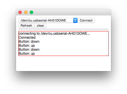
Chrome App
Finally, as seen in the preceding videos, I am using sometimes a serial logger a little bit different. Instead of using a python program, a socket between HTML5 and hosted program or the Arduino IDE I decided to create my own serial reader.
It is entirely written in HTML5 and JavaScript. As known, JavaScript standard does not support serial port communication, but the Chrome API does. Those functions can be used in a plugin in Chrome.
The plugin is not the best serial monitor ever, but it displays in text all the received information and, if the information starts by 1234, reads the fifth character of the string which contains the number of bytes to read to build the number and displays it using a progress bar in the interface.
The progress bar range is dynamically adjusted taking into account the received numbers.
The source code can be downloaded below.
Webcam
A few weeks ago I bought a Banana Pi (similar to a Raspberry Pi) and set it up running Bananian, a variation of Debian without any GUI installed. A few months ago I built a Prusa i3. I wanted to be able to control the process form the next room or from the living room. Therefore, I decided to install a webcam on the Banana Pi to send me through Telegram photographs or videos.
I bought the Logitech C270. Once plugged to the Banana pi it was automatically recognized (lsusb).

In order to take pictures I used fswebcam from command line.
~$ sudo apt-get install fswebcam
~$ fswebcam image.jpg
The second command will take a picture and save it to "image.jpg".
Recording a video is a little bit tougher. At first I installed ffmpeg, but it is deprecated, so I decided to use avconv for recording and arecord to add audio support to the recordings:
~$ sudo apt-get install libav-tools
~$ sudo apt-get install alsa-utils pulseaudio
Once installed we need to know the identificator of our microphone. It can be seen executing:
~$ sudo arecord -l
Now are able to record video using the webcam executing:
~$ sudo avconv -f video4linux2 -s 640x360 -i /dev/video0 -f alsa -i plughw:U0x46d0x825,0 -ar 22050 -ab 64k -strict experimental -t 20 -vcodec mpeg4 -y webcam.mp4
To start recording using a user that is not in the sudoers file, we will have to add the users to the groups video and audio.
In3
The incubator reads periodically information from the outside world. Two of the three boards designed to manage the incubator have input devices.
The thermometer board can read the temperature and humidity of the environment using a DHT11 sensor. It sends the information through a full duplex connection wire. Sensor readings are digital, not analog.
The control panel board has implemented a rotary switch to deal with the user.
The boards and code of this two input devices can be found in the final project page.