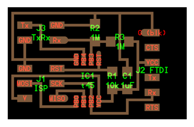
The example hello_txrx_45.png circuit.
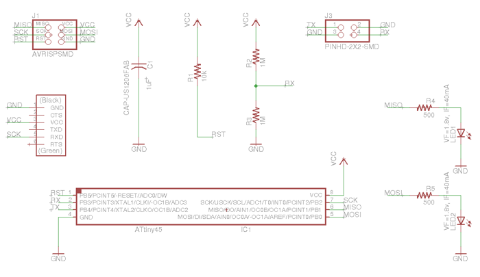
EagleCAD schematic of transmit-receive step response circuit with two status indicator LEDs.
EagleCAD schematic of transmit-receive step response circuit with two status indicator LEDs.
- Start with the microcontroller IC in the middle of the circuit board. Mostly likely all the other devices need to connect to the microcontroller pins.
- If they are used in the circuit, put the FTDI connector pins on one side (e.g. left of the IC) and the ISP connector on the other side (e.g. right of the IC).
- Think about power "busses". Assuming it is a DC circuit you will need positive (Vcc) and negative (Gnd) power connections. For example run Vcc bus across the top and right side of the circuit and run the Gnd bus on the bottom and left side.
- Rotate the Microcontroller IC, FTDI connector and ISP connectors to orient them to create the shortest path to Vcc and Gnd.
- Put the I/O devices (e.g. pushbuttons, LEDs, etc.) near the Microcontroller IC pins they are connected to.
- Place the resistors, caps, crystals, etc. where they are needed.
- To avoid jumper wires, use resistors and capacitors to bridge over routes. You also usually need to run routes under the Microcontroller IC and around the ISP pins.
- Hold down the CTRL key when drawing routes to jump finer increments and be placed into in-between spots. I found this did not work on the Ubuntu version of EagleCAD. Holding the CTRL key allowed me to move in smaller increments but it still jumped to the original grid. I got around this issue by reducing the spacing for the main grid and was able to place everything exactly where I wanted it.
- If you left mouse click on the pin that an air wire is connected to, EagleCAD will highlight all of the related pins (route endpoints) that are electrically the same. This is helpful for finding the most efficient routes. You can use this to "daisy chain" connections. For example, every Vcc connection doesn't have to go directly to the Vcc pin of the power supply. All you need to do is connect to the closest Vcc connection.
Programming
- Using the ATtiny45 data sheet and referencing the internet, I "reverse engineered" the example C program called "hello.txrx.45.c". As I did so, Neil's quick explanation during lecture of how the program worked started to make sense.
- I added additional documentation to the program and added code to control the two LED status indicators.
// // hello.txrx.led.45.c // // step response transmit-receive hello-world // 9600 baud FTDI interface // // Neil Gershenfeld // 11/6/11 // // (c) Massachusetts Institute of Technology 2011 // Permission granted for experimental and personal use; // license for commercial sale available from MIT. // // Modified by Scott Zitek 4/5/2014 // to add more comments and two status indicator LEDs #include < avr/io.h > #include < util/delay.h > #define output(directions,pin) (directions |= pin) // set port direction for output #define set(port,pin) (port |= pin) // set port pin #define clear(port,pin) (port &= (~pin)) // clear port pin #define pin_test(pins,pin) (pins & pin) // test for port pin #define bit_test(byte,bit) (byte & (1 << bit)) // test for bit set #define bit_delay_time 100 // bit delay for 9600 with overhead #define bit_delay() _delay_us(bit_delay_time) // RS232 bit delay #define half_bit_delay() _delay_us(bit_delay_time/2) // RS232 half bit delay #define settle_delay() _delay_us(100) // settle delay #define char_delay() _delay_ms(10) // char delay #define nloop 100 // loops to accumulate #define serial_port PORTB #define serial_direction DDRB #define serial_pin_out (1 << PB2) #define transmit_port PORTB #define transmit_direction DDRB #define transmit_pin (1 << PB4) //added to configure LED connected to ATtiny45 pin PB0 #define led1_port PORTB #define led1_direction DDRB #define led1_pin (1 << PB0) //added to configure LED connected to ATtiny45 pin PB1 #define led2_port PORTB #define led2_direction DDRB #define led2_pin (1 << PB1) void put_char(volatile unsigned char *port, unsigned char pin, char txchar) { // // send character in txchar on port pin // assumes line driver (inverts bits) // // start bit // clear(*port,pin); bit_delay(); // // unrolled loop to write data bits // if bit_test(txchar,0) set(*port,pin); else clear(*port,pin); bit_delay(); if bit_test(txchar,1) set(*port,pin); else clear(*port,pin); bit_delay(); if bit_test(txchar,2) set(*port,pin); else clear(*port,pin); bit_delay(); if bit_test(txchar,3) set(*port,pin); else clear(*port,pin); bit_delay(); if bit_test(txchar,4) set(*port,pin); else clear(*port,pin); bit_delay(); if bit_test(txchar,5) set(*port,pin); else clear(*port,pin); bit_delay(); if bit_test(txchar,6) set(*port,pin); else clear(*port,pin); bit_delay(); if bit_test(txchar,7) set(*port,pin); else clear(*port,pin); bit_delay(); // // stop bit // set(*port,pin); bit_delay(); // // char delay // bit_delay(); } int main(void) { // // main // static unsigned char count; static uint16_t up,down; // Added to create variable to store the result of up value minus down value static uint16_t value; // // set clock divider to /1 // CLKPR = (1 << CLKPCE); CLKPR = (0 << CLKPS3) | (0 << CLKPS2) | (0 << CLKPS1) | (0 << CLKPS0); // // initialize output pins // set(serial_port, serial_pin_out); output(serial_direction, serial_pin_out); clear(transmit_port, transmit_pin); output(transmit_direction, transmit_pin); // Initialize LED1 status indicator clear(led1_port, led1_pin); output(led1_direction, led1_pin); // Initialize LED2 status indicator clear(led2_port, led2_pin); output(led2_direction, led2_pin); // // init A/D // // Data sheet Pg134-135 ADMUX is the ADC Multiplexer Selection Register. // REFS2=0, REFS1=0,and REFS0=0 sets "Vcc used as voltage...... // reference, disconnected from PB0 (AREF)" // ALDAR=0 sets ADC presentation for right adjust - see data sheet pg137 // MUX3=0, MUX2=0, MUX1=1, and MUX0=1 - this sets input channel // for Single ended-input ADC3 (PB3). Positive Differential // input, Negative Differential input, and gain N/A. // ADCSRA is the ADC control and status register A // see data sheet pg136. prescaler select bits 1,1,1 set ADC prescaler for // division factor 128. // simplifies by basically truncating 10-bit ADC to 8-bit ADC result. ADMUX = (0 << REFS2) | (0 << REFS1) | (0 << REFS0) // Vcc ref | (0 << ADLAR) // right adjust | (0 << MUX3) | (0 << MUX2) | (1 << MUX1) | (1 << MUX0); // PB3 ADCSRA = (1 << ADEN) // enable | (1 << ADPS2) | (1 << ADPS1) | (1 << ADPS0); // prescaler /128 // // main loop // while (1) { // // accumulate // up = 0; down = 0; for (count = 0; count < nloop; ++count) { // // settle, charge // settle_delay(); set(transmit_port, transmit_pin); // // initiate conversion // ADCSRA |= (1 << ADSC); // // wait for completion // while (ADCSRA & (1 << ADSC)) ; // // save result // up += ADC; // // settle, discharge // settle_delay(); clear(transmit_port, transmit_pin); // // initiate conversion // ADCSRA |= (1 << ADSC); // // wait for completion // while (ADCSRA & (1 << ADSC)) ; // // save result // down += ADC; } // // Control LED status indicators // // Subtract "down" value from "up" value and store the result in "value" // "value" is the number displayed by the example Python program. value = up - down; // Energize LED1 when the value is above a predefined value (e.g. 5000) if (value > 5000){ set(led1_port, led1_pin); // Execute if condition is met } else{ clear(led1_port, led1_pin); // Execute if condition is not met } // Energize LED2 when the value is above a predefined value (e.g. 7000) if (value > 7000){ set(led2_port, led2_pin); // Execute if condition is met } else{ clear(led2_port, led2_pin); // Execute if condition is not met } // // send framing // put_char(&serial_port, serial_pin_out, 1); char_delay(); put_char(&serial_port, serial_pin_out, 2); char_delay(); put_char(&serial_port, serial_pin_out, 3); char_delay(); put_char(&serial_port, serial_pin_out, 4); // // send result // // "up" and "down" are both unsigned 16-bit integers. // so we must send upper and lower bytes of each as separate characters. put_char(&serial_port, serial_pin_out, (up & 255)); char_delay(); put_char(&serial_port, serial_pin_out, ((up >> 8) & 255)); char_delay(); put_char(&serial_port, serial_pin_out, (down & 255)); char_delay(); put_char(&serial_port, serial_pin_out, ((down >> 8) & 255)); char_delay(); } } - Using avr-gcc in Ubuntu, I compiled the c program to hex
sudo make -f hello.txrx.led.45.make -
I used avrdude and an ISP to write the program to the ATtiny45. NOTE: I did not perform the typical step of writing the fuse settings to the ATtiny because there is no external crystal the default settings should work.
sudo make -f hello.txrx.45.led.make program-avrisp2
Testing
- I soldered copper foil to the end of the circuit's transmit wire and another piece of copper foil to the circuit's receive wire.
-
I used the example Python program and the FTDI USB to serial cable to communicated with the circuit and display the analog information.
python hello.txrx.45.py /dev/ttyUSB0
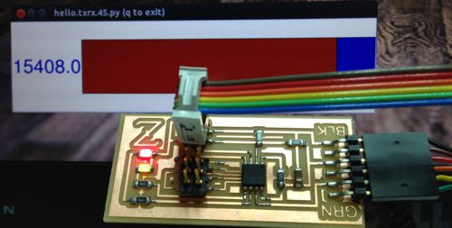
Completed transmit-receive step response circuit with both status indicator LEDs illuminated and Python readout program running in the background.
-
I experimented to see what affected the value from the circuit.
- Size of foil pieces
- Distance between foil pieces
- Proximity of objects to foil.
- Material properties of object near foil
- Etc.
- I set up a little experiment to see if I could detect the difference between mill and water. I put the transmit and receive foil pieces on the outside of a plastic cup and documented the readout for different quantities of each liquid.
- A video of the circuit sensing the water level and controlling the status LEDs can be seen here. Notice that the first LED illuminates when the water level reaches the red line on the cup. The second LED illuminates when the water level reaches the blue line on the cup.
- I could not detect a significant difference between the milk and water but the results indicated that there was a relationship between liquid level and the readout value.
- I also tested the circuit for measuring pressure. I placed a piece of soft 1.5 inch thick foam between the copper foil pieces connected to the transmit and receive wires. When I pressed down on the TX-foil/foam/Rx-foil sandwich using a cup, the circuit readout value increased proportionally. I was able to use one LED to indicate "medium" pressure and the other LED to indicate "high" pressure.
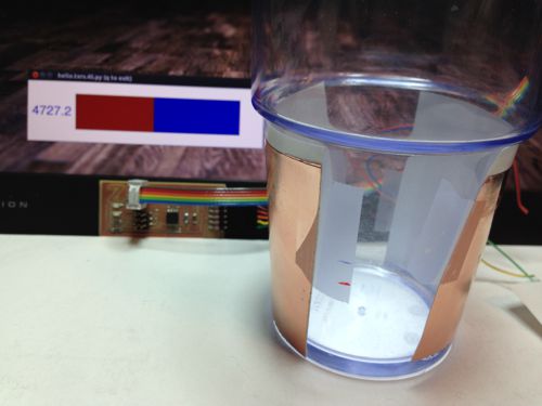
Plastic cup with transmit and receive foil pieces attached.
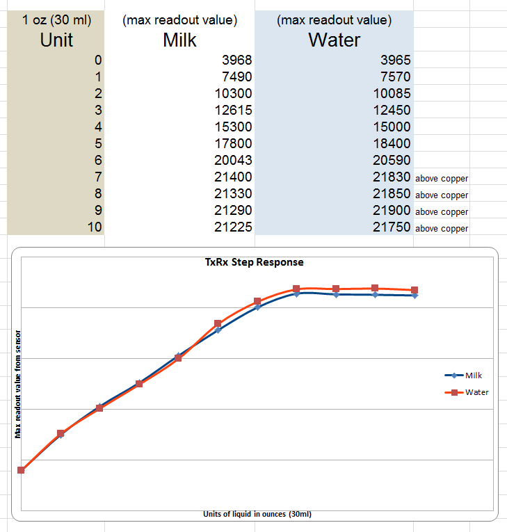
Results of testing detection of milk and water at various levels. Notice, it did not detect changes well once liquid level was above foil.
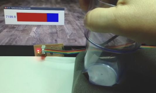
Testing a pressure sensor based upon the step response circuit.
Files
- Eagle CAD schematic file for step response board with two LED status indicators.
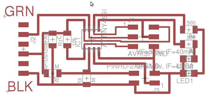
- Eagle CAD board layout file for step response board with two LED status indicators.
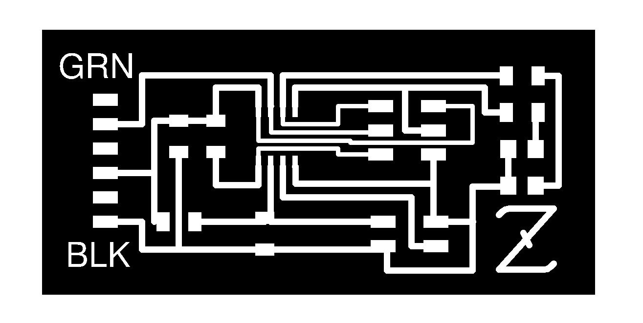
- Diagram showing where components go on step response board with two LED status indicators - in png format.
- Step response board with two LED status indicators - Circuit board traces in png format
- Step response board with two LED status indicators - Circuit board interior in png format.
- Example c program modified to also control the two status indicator LEDs.
- Make file for the above c program.
- Example python program to run on PC and display step response input the values received via the FTDI.
Back to index