
Embeded Programming Class
7th Worldwide gathering for Fab Academy 2015 feat. prof. Neil Gershenfeld
18 February
12 weeks to Final project
Class
Writing code for Microcontrolers, a brief Intro
The architectures [+]
- Von Neumann - memory and code are together
- Harvard - memory and code are separete
- RISC (reduced instructions), CISC (complex instructions)
- microprocessor(all functions interact from diferent , microcontroller (all functions are built in, although less powerfull)
- FPGA, CPLD
- ALA
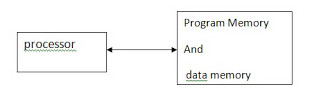
V.Neuman - Relation between the diferent parts
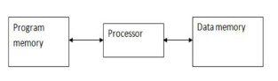
Harvard - Relation between the diferent parts
The Programmers [+]
- FABISP - the chosen one
Program controler build on week04
The Program Languages [+]
Note on Assembly - low level language
Why learn Assembly? Because there are sections of code that demand a rapid, direct and, therefore, efficient communcation to the hardware.
Assigments:
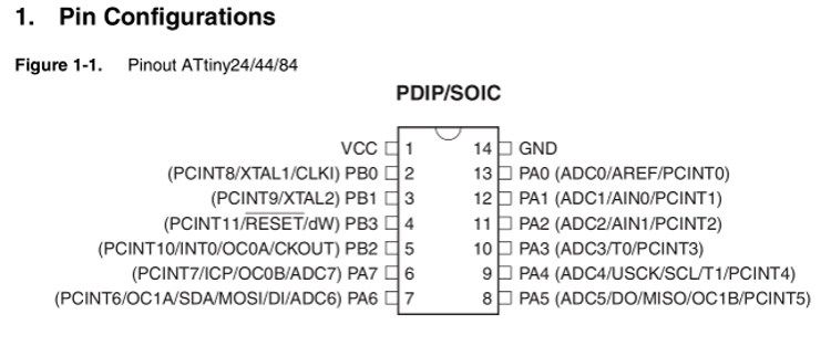
1. Reading ATTINY44 data sheet check it here
Chalange accepted!
First off all, breath in and out, this is not going to be a easy path. Reading a datasheet of this type is like knowing the map to the holy grail, so take your time.Powerful information, but dificult to grasp for a first timer.
Because is full of data, wierd acronyms, dense information on the relation and interdependence between parts, multiple functionalities, concepts of hardware architecture, memory, clock, power management, spleeping modes, writen in a technical language, for a stranger to that field extra time needs to be taken to just absorb all concepts and understanding of it all.
Not knowing half of last week it was almost impossible to avoid the birth of my semi-frankensteiny first echo-hello board.Why?
Let's say it would have been useful to just give this "bible" on first week presentation, saying:"this is our new religion" learn it good.
2. Trying as many program languages as possible: assembly, C programing, arduino
Deeper into the rabbit hole - ASSEMBLY
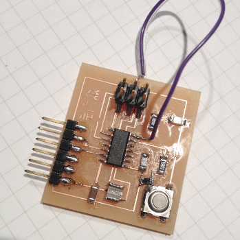
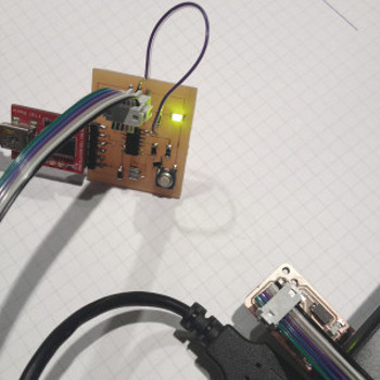
Last week after debugging time with Francisco we realized I had miss placed the MOSI connection to Pin PA7 so an external wire had to be added like shown in the picture to the side.
Also another connection was missed between the button and the VCC so had to bridge with an 0OHM resitor.
Ran in through Arduino Software uploading a sample program just to check if connections where fine. And yes it was a working board, despite of the extra appendix.
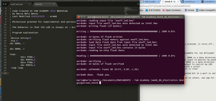
For that we had to instal gavrasm and then we followed step by step the tutorial on Assembly coding - Scott Ziteck's week08 for applying it to initial state LED OFF and ON on pushing button program.
Had to go through the attiny44 data-sheet for more knowledge on each pin and port so that the programing of data went smoothly and the final behavior would be something like in the animation to the side of this text. Needless to say that if you see a LED going on and off on pushing means this was a completed and successful mission overall.
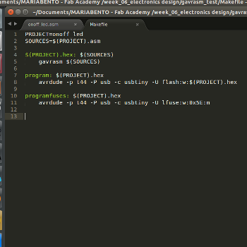
We used Sublime text for text editing adapted the pin numbers to our own pins and re-wrote the code. Generated the .asm file. After that come the Makefile from which we could program the fuses and then add the final Project program to the micro-controller.
[Note]:Code available on the links in the bottom of this page
Programming the echo hello-world board -SECOND ROUND C Code
LED initial state ON, press button OFF
For that performed a few changes on the written code switching
// blink sketch
// Maria Melo Bento
// 16/03 2015
// licens CC
#include < stdio.h>
#include < avr/io.h>

int main()
{

DDRA |= (1<< DDA6); // set as output. set bit in register. LED
DDRA &= ~(1<< DDA7); // set as input. clear bit in register. BUTTON
PORTA |= (1<< PORTA7); // set as input. enable port resistor in PA7. BUTTON

while(1)
{

  if ((PINA & (1<< PINA7))==0)//test if the bit is set.
  {
    PORTA |= (1<< PORTA6);

  }//closing if statement

  else
  {
    PORTA &= ~(1<< PORTA6);//iPORTA "output" |= "set bit" (6) "on pin 6"

  }// close else

}//while loop closing

}//closing main
Then tried to program it so the LED would hold on its behavior until next button push
        // button led variable button onoff (20mhz keeps processor changing to fast)
// Maria Melo Bento
// 20/04 2015
// licens CC
#include < stdio.h>
#include < avr/io.h>


int main()
{

int buttonstat=0; //initial state button

DDRA |= (1<< DDA6); // set as output. set bit in register. LED
DDRA &= ~(1<< DDA7); // set as input. clear bit in register. BUTTON
PORTA |= (1<< PORTA7); // set as input. enable port resistor in PA7. BUTTON


while(1)
{

  if ((PINA & (1<< PINA7))==0)//test if the bit is set.
  {

    buttonstat = !buttonstat;//!(!) inverse of buttonstat
  }//closing if statement

  if (buttonstat==0)
  {

    PORTA &= ~(1<< PORTA6);//iPORTA "output" |= "set bit" (6) "on pin 6"
  }


  else
  {
    PORTA |= (1<< PORTA6);

  }// close else

}//while loop closing


}//closing main
Idea for morse code based blinking -Third ROUND Arduino IDE
/*
  Blink
  Turns on an LED on for one second, then off for one second, repeatedly.

  Most Arduinos have an on-board LED you can control. On the Uno and
  Leonardo, it is attached to digital pin 13. If you're unsure what
  pin the on-board LED is connected to on your Arduino model, check
  the documentation at http://arduino.cc

  This example code is in the public domain.
  by Scott Fitzgerald

  modified March 2015
  by Maria Melo Bento

 */
const int buttonPin = 7;     // the number of the pushbutton pin
const int ledPin =  6;      // the number of the LED pin

// variables will change:
int buttonState = 1;         // variable for reading the pushbutton status

void setup() {
  // initialize the LED pin as an output:
  pinMode(ledPin, OUTPUT);
  // initialize the pushbutton pin as an input:
  pinMode(buttonPin, INPUT);
}


// the loop function runs over and over again forever
void loop() {

  // read the state of the pushbutton value:
  buttonState = digitalRead(buttonPin);

  // check if the pushbutton is pressed.
  // if it is, the buttonState is HIGH:
  if (buttonState == HIGH) {
  digitalWrite(ledPin, HIGH);   // turn the LED on (HIGH is the voltage level)
  delay(20);              // wait for a second
  digitalWrite(ledPin, LOW);    // turn the LED off by making the voltage LOW
  delay(20);              // wait for a second
  digitalWrite(ledPin, HIGH);   // turn the ledPin on (HIGH is the voltage level)
  delay(20);              // wait for a second
  digitalWrite(ledPin, LOW);    // turn the ledPin off by making the voltage LOW
  delay(20);              // wait for a second
  digitalWrite(ledPin, HIGH);   // turn the ledPin on (HIGH is the voltage level)
  delay(20);              // wait for a second
  digitalWrite(ledPin, LOW);    // turn the ledPin off by making the voltage LOW
  delay(40);              // wait for a second

  digitalWrite(ledPin, HIGH);   // turn the ledPin on (HIGH is the voltage level)
  delay(40);              // wait for a second
  digitalWrite(ledPin, LOW);    // turn the ledPin off by making the voltage LOW
  delay(20);              // wait for a second
  digitalWrite(ledPin, HIGH);   // turn the ledPin on (HIGH is the voltage level)
  delay(40);              // wait for a second
  digitalWrite(ledPin, LOW);    // turn the ledPin off by making the voltage LOW
  delay(20);              // wait for a second
  digitalWrite(ledPin, HIGH);   // turn the ledPin on (HIGH is the voltage level)
  delay(40);              // wait for a second
  digitalWrite(ledPin, LOW);    // turn the ledPin off by making the voltage LOW
  delay(40);              // wait for a second

  digitalWrite(ledPin, HIGH);   // turn the ledPin on (HIGH is the voltage level)
  delay(20);              // wait for a second
  digitalWrite(ledPin, LOW);    // turn the ledPin off by making the voltage LOW
  delay(20);              // wait for a second
  digitalWrite(ledPin, HIGH);   // turn the ledPin on (HIGH is the voltage level)
  delay(20);              // wait for a second
  digitalWrite(ledPin, LOW);    // turn the ledPin off by making the voltage LOW
  delay(20);              // wait for a second
  digitalWrite(ledPin, HIGH);   // turn the ledPin on (HIGH is the voltage level)
  delay(20);              // wait for a second
  digitalWrite(ledPin, LOW);    // turn the ledPin off by making the voltage LOW
  delay(120);              // wait for a second
}
else {
    // turn LED off:
    digitalWrite(ledPin, LOW);
  }
}
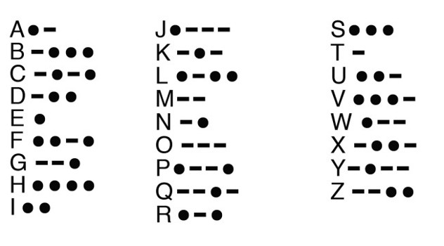
Morse Code lesson by the USA Army
The idea was to create a basic blink routine for a SOS signal to be sent when the button was trigger. Starting with defining pins for both button and LED. Then first step was setting up input pin - button and output pin - LED.
After that and according to Morse code rules setting the high values and delays for the LED in a proper timing so it could be understandable.
First block of code corresponds to a S letter
Second block of code corresponds to a 0 letter
Third block of code corresponds to a S letter
If the button is set LOW the routine will stop
Also decided to do another version of this Morse Code in C that has a better definition for each of the letters.