Electronics Production Class
4th Worldwide gathering for Fabacademy 2015 feat. prof. Neil Gershenfeld
11 February
15 weeks to Final project
The PCB world aka Printed Circuit Board
Still a newbe to all this world of electronics I began with some of the basics available at sparkfun website (all of which you can access on the link above).
They explain it very strait forward exploring the following subjects:
- What is Electricity?
- Voltage, Current, Resistance, and Ohm s Law
- Voltage is the difference in charge between two points.
- Current is the rate at which charge is flowing.
- Resistance is a material's tendency to resist the flow of charge (current).
- Ohm's Law
- What is a Circuit?
- Connector Basics
- Soldering
- Signals

1st baby steps
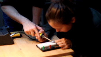
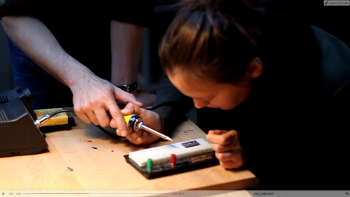
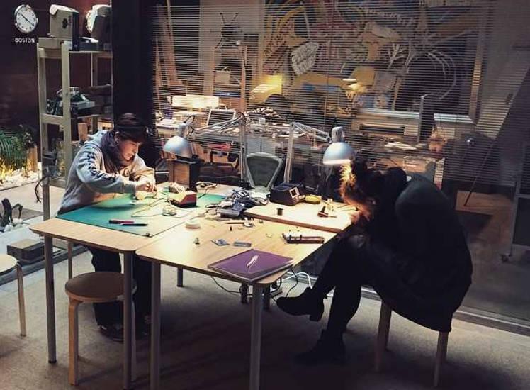
A few weeks ago we had our first introduction to electronics done by Francisco. As non of us in our group was familiar with electronics we asked for a class in advance. So promptly Francisco had us soldering like crazy!
Board Designs
When the actual class on electronics was held we where ready to go.
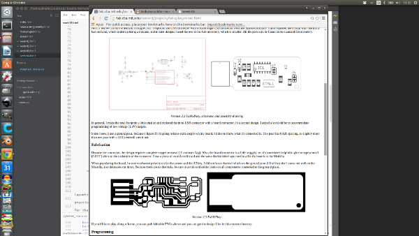
First step review available designs:David's design, Andy's design and Valentine's design
Make the FabISP in-circuit programmer
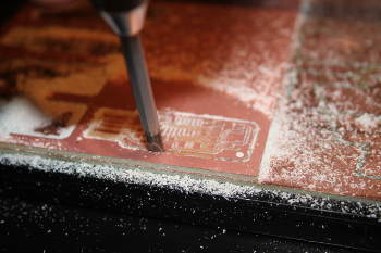
1. Choose design and mill it!
For this assignment we were to build a pcb board from a previous design one that we could pick from diferent layouts available
We chose Andy's very practical on the making.
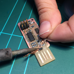
First collect all the components, understand how they are conected, be aware of polarities and whatchout for the tiny spaces where solderings might join and the cause malfuctions in the board, namely short-circuits.
Failiures and Sucesses:
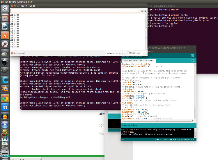
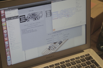
Using Fab modules is amazingly easy. Uploading the png's and milling the outline result was a super simple task.
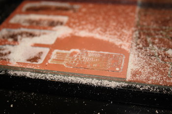
Dealing with the Roland Modela demands some patience but once you get the pace right its on and off bits mill and ready in a few minutes.
Taking the milled board off can sometimes be a chalange once it was previously attached with two-sided-tape to the sacrificial layer board.
2. Stuff the board in less then 10min
Well...it still doesn't happen like that, but it will - with a lot more hours of soldering ahead i am sure.
Failiures and Sucesses:
Dispite of being very careful and soldering just with the minimum necessary still some parts get conected and from arduino software analisis with get and error msg.
2.1 Debug Time begins
Check Polarities - Diods are placed correctly but one of them was touching ground while it wasn't supose to.
Disoldering - Remove the excess soldering with tape like it shows in the picture bellow.
After taking care of that problem the board was working fine!
Now that I was getting the hang of it I needed on more challange. So I moved to the next board milling

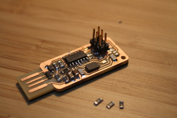
Second production - Andrew Leek's FTDI USB board
Failiures and Sucesses:
This board of elegant design is very fragile after milling, even more if you mill with incresed offset values by mistake, as I did, you can really get small traces that can easily split when the baord is removed. That happened to me and those have to be emended whit soldering.
Conecting it to the first already done PCB as a programmer and after finishing the soldering on this one also gave me an error while uploading the program through Arduino software warning me that it couldn't find the device.
So again physical debugging begins
First mistake: Leds weren't in the right position aldough one was blinking and the other not.
Try it again still same warning.
Turned the wrong one but accidentely burned it for excessive heat, so had to get a new one. So finaly before I could achieve sucess on this mission had to find another possible error. And there it was pin 01 and pin 02 were slightly touching. Once that was detected by my collegue Anders and I in GROUP DEBUG as we call it, it was working fine. Leds were blinking and it was a healthy baby board!