Resume of the lesson
Using the laser cutter and the vynil cutter is a great moment of the fablab course ! To test it, we have first to create a 2D design, idealy with some conectors, in order to be able to assemble various pieces together. This unions will be dependent :- of the roughness of the material used
- of the variability of the thickness the board have, between 2 boards, but also in the same board ( especially true for wood panel )
- of the precision of the laser we'll set up : more or less material could be removed
The dark side is more difficult work ( could you imagine drawing a 3D volume without using the mouse?? ) , and also more reflexion about where you will need variable and where not. Another dark side of parametric design ? To found the correct software to use , especially if you're using a Mac :
- the "famous" parametric module Grasshoper for Rhino doesn't exit for mac
- Autodesk Inventor Fusion don't have parametric funccion , when the PC version of Inventor, and Inventor Pro have it
Home Work
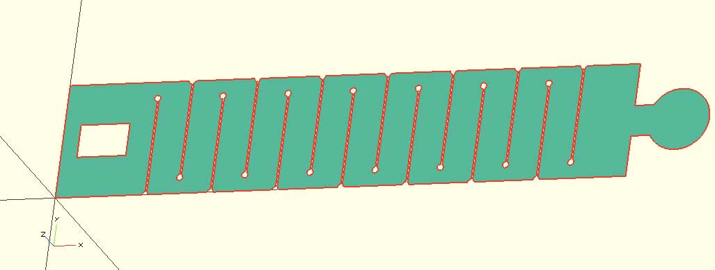
My parametric design will be the arm-head we need for the FunGun's project (electronics will come in a later stage). I've set up 10 variables, in fact , every value is a variable :
Above is the result. To fix the arm around the head, you slide the left side in the hole located at the opposite :
- the diameter of the circle = the lenght of the hole
- the width of the support of the circle = width of the hole
- but nit exactly egual ! both value have a tolerance you can set up in the Variable part, so you can adjust the union depending the paramers of the material you are using
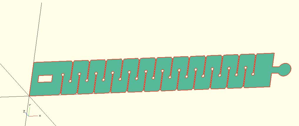
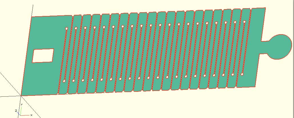
Setting the variable "number_cut" at 7 instead of 12 give you this
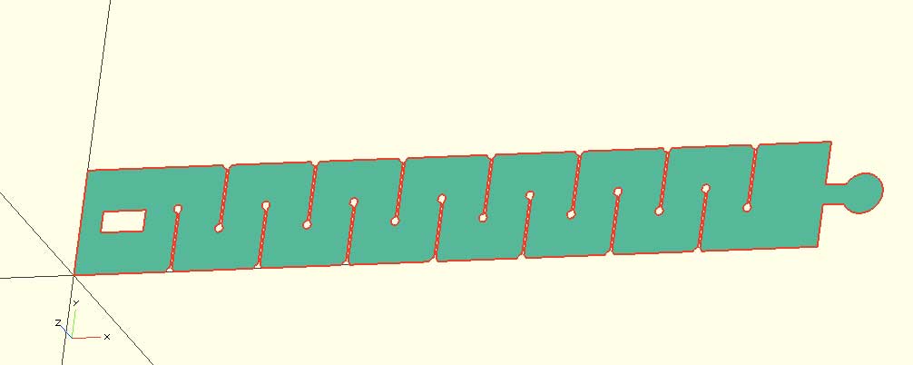
Then We could give more flexibility, changing the height of the arm (height_arm) and the height of the cut (height_cut) :
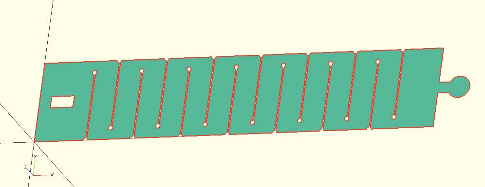
Changing now the diameter and the size of the lock :
An changing all together :
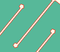
Very powerfull indeed. Last detail , some circle at the end of the cut line in order to procect the material form cracks :
Let see the code used in Opensacad for this arm-head :
// parametric arm by Paul Sernine, for the Fabacademy 2014
//
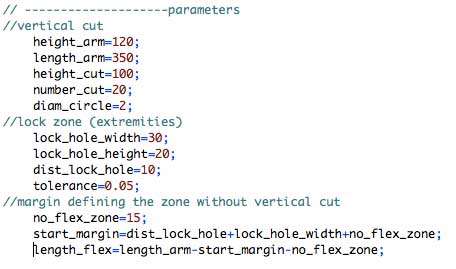
// --------------------parameters
//vertical cut
height_arm=50;
length_arm=350;
height_cut=30;
number_cut=12;
diam_circle=2;
//lock zone (extremities)
lock_hole_width=20;
lock_hole_height=10;
dist_lock_hole=10;
tolerance=0.05;
//margin defining the zone without vertical cut
no_flex_zone=15;
start_margin=dist_lock_hole+lock_hole_width+no_flex_zone;
length_flex=length_arm-start_margin-no_flex_zone;
// --------------------modules of the cutting parts
module bottom_cut() {
translate([start_margin,0,0])
for (i = [0:number_cut-1]) {
translate([i*length_flex/number_cut,0,0])
square([1,height_cut]);
translate([i*length_flex/number_cut,height_cut,0])
circle(diam_circle);
translate([i*length_flex/number_cut,0,0])
circle(diam_circle);
}
}
module full_cut() {
union() {
bottom_cut();
translate([dist_lock_hole,(height_arm-lock_hole_height)/2,0])
square([lock_hole_width,lock_hole_height]);
translate([length_flex/number_cut/2,height_arm-height_cut,0])
bottom_cut();
}
}
// --------------------module of the plein part
module lock() {
square([lock_hole_width,lock_hole_height*(1-tolerance)]);
translate([lock_hole_width,lock_hole_height*(1-tolerance)/2,0])
circle(lock_hole_height*(1-tolerance));
}
module full_arm() {
union() {
square([length_arm,height_arm]);
translate([length_arm-diam_circle,(height_arm-lock_hole_height)/2,0])
lock();
}
}
// --------------------final drawing
difference() {
full_arm();
full_cut();
}