Mainly press-fit approach could be described as going from 2D forms to 3D constructions. This process includes several parts of material connected together with friction only. To achieve this a flat and thin material is taken as a base work-piece. Material is then cut in a way to form the dimensions of the future product and slots for connection needs. For this purpose a laser-cutter or a milling machine could be used.
To apply press-fit technology to our project we'll be making a real prototype of the final project using a 3D-model we worked out earlier.
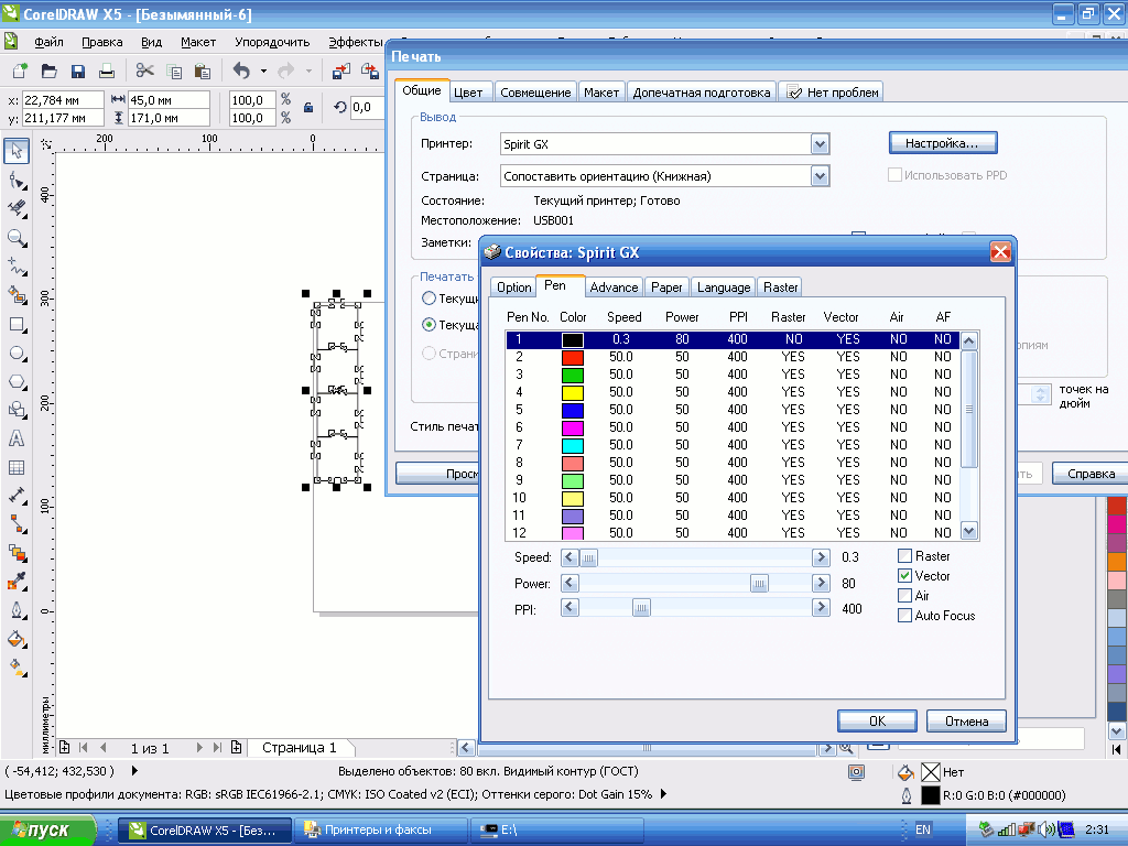
The first thing to do in any process of laser cutting is to prepare production image files in a format needed for the machine. In our case we are cutting with "GCC LaserPro Spirit GX". It uses CorelDraw and a printer driver to send vector graphics to the laser-cutter.
Our 3D sources are produced with Autodesk Inventor and to import the actual image to be cut in CorelDraw the best practice is to start a 1:1 drawing in Inventor and export it to an intermediate DXF format. The files prepared for today's cutting can be accessed below:
After arranging the image according to our needs (for example, we could rotate the image according to the material formation) we need to set the properties for cutting. The main properties for most of the machines are "power" and "speed". Usually the best practice is to write down a list of successful regimes tested on different types of materials and their thickness. Those could differ from machine to machine but in our case you can consult the list of cutting regimes for "GCC LaserPro Spirit GX".
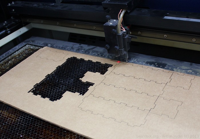
Cutting material is a rather easy operation since a laser-cutter does all the work. Though, remember, that leaving the machine unattended is strictly prohibited, especially when you are experimenting with cutting regimes.
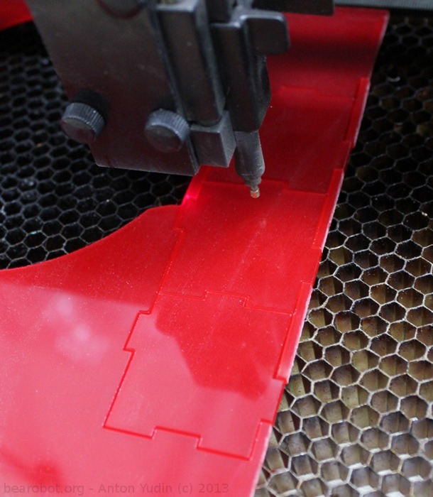
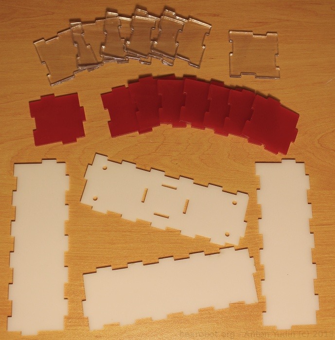
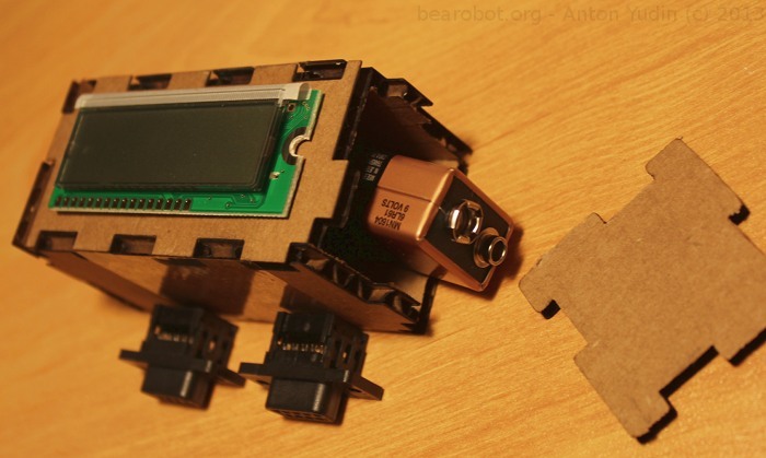
This time we are cutting cardboard (carton) and acrylic glass of different colours. Depending on the machine you are using cardboard cutting can become a problem (as in our case). "GCC LaserPro Spirit GX" is not capable of getting a quick and high quality cut on this material. The problem is that cardboard is double-sided with some space between the two sides. One run performs a good cut on one side, but only slightly and partly cuts the back side. Second run burns the top side.
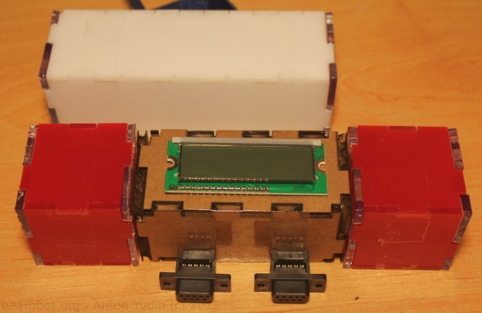
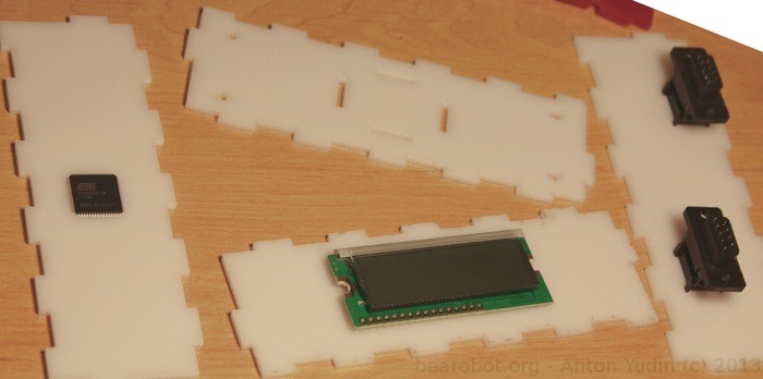
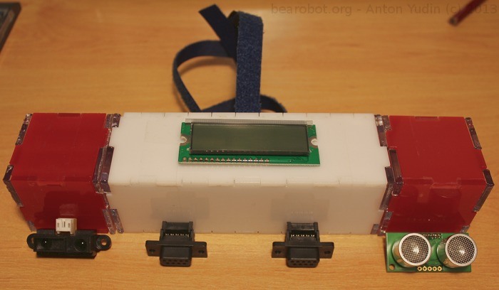
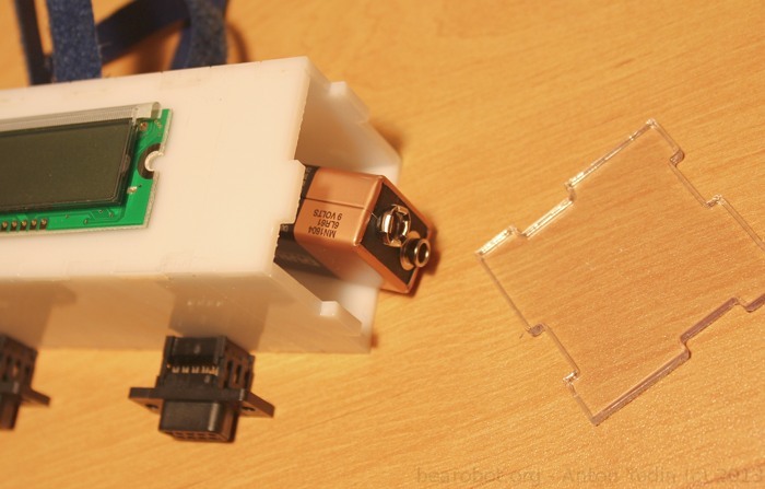
Everything is cut and we can start experimenting with the layout of those electronic parts we have in mind to use in the final assembly. On the picture you can see the microcontroller side, the indication side and the interface side of the "O" module (white colour).
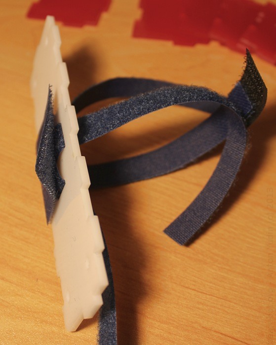
The last functional part is the mounting part. This time we are working on the ergonomic aspect of mounting the construction kit on hand. A velcro fastener is used for this purpose. It lets easier control of the length of a strap to adjust to a hand dimensions.
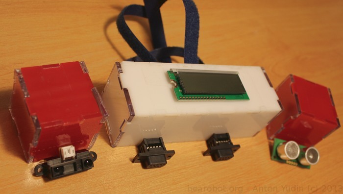
Below are the pictures describing the final assembly, mainly concentrating on physical dimensions of the parts.
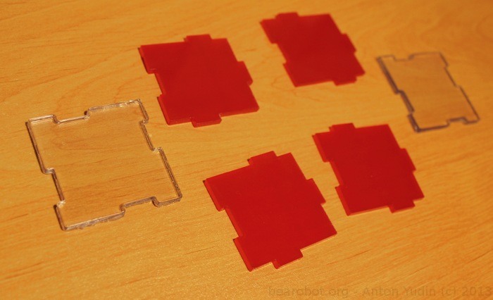
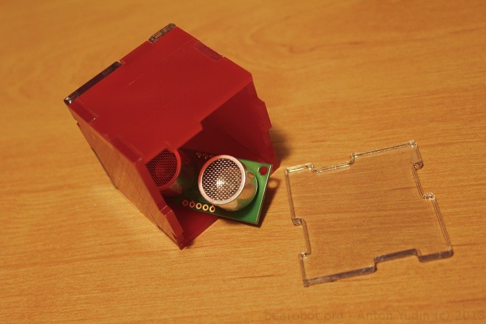
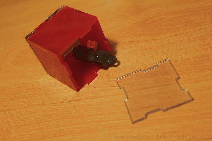
Some pictures demonstrate what functions could possibly carray the "H" modules (red cubes): distance measurement.
The inner parts of the "O" module could be occupied with a battery whether it is chargeable or non-chargeable type.
Finally, as it was shown earlier in week_2/project_first_approximation's 3D-model, dimensions of all modules are alike. For example the side of the "H" cube is taken for X and the length of the "O" module was taken as 3*X.
Here we can see that a smaller version could be used to reduce material usage and user convenience. Later we'll make a 2*X version of the "O" module as it seems more practical and satisfies the dimensions of those electronic parts meant to be used.