Electronics Design
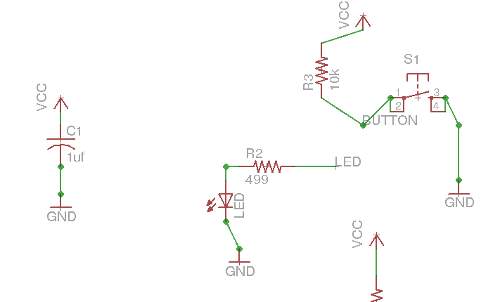
This weeks assignment was to add a button and LED to the "hello echo" board using eagle. After adding the libraries recommended by Anna, I added an LED, a corresponding 499 ohm resistor, the push button, and a 10K ohm pull up resistor. (As well as ground symbols where appropriate).
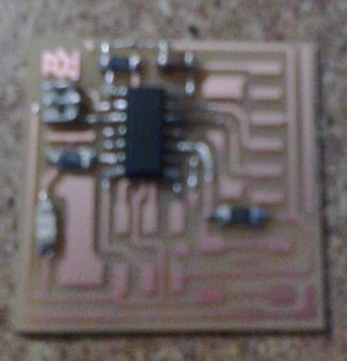
After finishing the schematic it was time for the fun part; rearanging the previous layout of the board to accomodate our new components and routing all of the new traces.
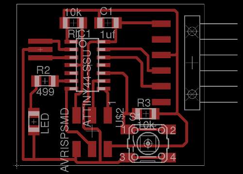
From here it was time to export the board layout as an image to be used by the Fab Modules to mill the board. Before beginning this class I wrote up short tutorial that covers this in more detail here: https://docs.google.
Milling and Stuffing:
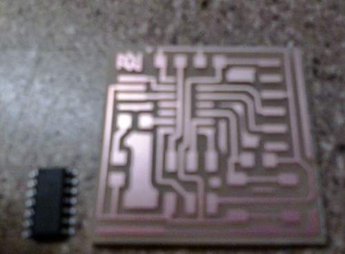
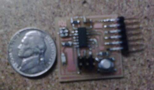
I then began the process of programming the new hello echo board.
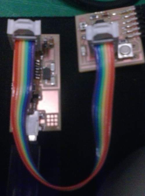
Unfortunately after having issues loading the program onto the board, reflowing solder and momentarily getting it to work, I broke off the 6 pin ftdi programming header. Coming with it were all of the traces connected to it so the only thing salvageable are the components on the board. I will re-mill/stuff it and try again.

