About me
Final project -
development
Final project
Weekly projects
Wk 16 Machine Design (May 20)
Assignment:
• Make a machine, including the
end effector
• build the passive parts and operate it manually
• document the group project and your individual
contribution
Note: Fablab
were providing
4
x
machine kits
(including 4 x
stepper motors
/ spindles, 4
x nodes plus
assembly
components).
I
document my individual participation for the group
assignment below and the group documentation can be
foud here.
I was tasked with taking photos and essential
documentation of the key stages for the group
project, so that the process would not be lost nor
time wasted on duplicate efforts. This means that
this individual documentation page looks very
similar to the group documentation page.
Settling
on an idea
Over the course of
the first few days, we all brought different ideas that might suit the
challenge of Mechanical and Machine Design and Build week. These
included a 3D scanning
bed; golf
putting exercise
machine; roulette-style
game to name a
few.
The
one that got
the overall
approval
by the group,
was an idea
from Philip
Hemstead
- a digitally
controlled
ball
tilting
maze game.
To crystallize
the project,
we titled it "Fabaryinth".
In this
game, incremental
movement of stepper
motors would
provide
the control
over
the tilt
level
of a
plane, upon
which the user
(through a PC
user interface
with
a
simple control
console,
would
try to guide a
ball
over a maze
obstacle
course
and into
a target
hole.
This
game would
include the
following
areas of
learning:
Machine
Design
Electronics
and stepper motor
control
(using
multiple
nodes)
Lasercutting /
Milling
Electronics
Assemby
of parts
Networking
of single node
communication
system
Programming
(input and
output)
See
tutorial
for overview.
Machine
Design
In
the first
instance, the
suggestion was
to use
all 4 stepper
motors
(probably as
it would be
stable,
and 4 were
provided, not
sure why).


I
challenged
this as I did
not think 4
stepper motors
would be
necessary - the
movement
could be
established
with maximum 2
or 3 if
the
design was
adapted. I
could see that
in order to
acheive a tilt,
a
certain degree
of freedom
of movement
would be
required. I
found this an
interesting
problem. To
see how much freedom,
I
quickly
cut three slots
in a flat
piece of cardboard
and placed it
over 3
leadscrews. It
revealed the
range of
free movement
that
would be
required
between the game-bed
and 3
guiding
leadscrews to
enable the
tilt, which,
to roll
a ball, would
only have to be
minimal.
This
is
demonstrated
below:

Personally,
I
am more
interested in
design
than
electronics
and programming,
and looking
back I would
have liked for
more
time to have
been allocated
for
each person to
present their
ideas on design development
and rationale,
especially on
transferring
the tilt to
the
game bed
effectively.
I
felt we moved
too quickly,
without asking
enough
questions
before
progressing.
However, I
acknowledge
that if my
team mates
hadn't applied
momentum, we
probably
would not have
finished the
task as
fully.
I
also
felt that to
some degree,
the cardboard
housing
template
supplied,
hindered our
thinking; the
heavy
framework was
unnecessary
for our
application.
I
couldnt help
but wonder if
we should
have stepped
back and
considered giving
a lighter
touch to the
housing and
attempting to
integrate
the
links
to the
game-bed?
Again as a
group, with a
big
task to
complete under
a
time
limit,
this would
have been a
big ask, so I
daren't
voice it!
With
a
broad
vision of the
extra
systems
required to
make the game
work,
essentially
a
custom-made
game-bed
and a
flexible
linkage
to transfer
the movement,
some
of the initial
tasks
were taken up
by the
four members
of our
group.
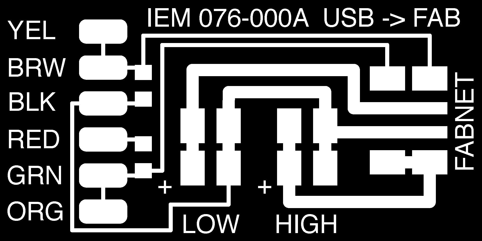
Electronics
I
looked into
the tutorials
on the Fabnet
Adaptor
board, downloaded
the file,
milled
it
on the Modela
and
soldered the
components
onto the board.
The ftdi cable
had to be customised
to suit the
board and the
single nodes.
The
detail is
shown
in the photos
/ diagram
below:


I
joined David
to follow the
testing of the
network
for connections
to Node
1,
PC
and
power
supply.
To help me
understand the
network and
for the
purpose of
documentation,
I suggested
placing the
network on
some cardboard
so that we could
mark up and identify
each part -
this is shown
below:

Cardboard
housing
The
main
part of this
task was
taken
up by Philip
and Michael.
This was
fiddly;
I tracked
the
process, and they
had to make
some
adjustments
and cut
some cardboard
leafs
away in
order to
create more
space inside
the housing so
that the spindles
would be in
true alignment
with
the housing
support guides.

Game-bed
This
task had been
assigned to
Kasper, but
nonetheless I
suggested the
idea
of
creating a
simple organic undulating
landscape form
in Solidworks
and then
to mill
it on the
shopbot using
a light foam board.
In my
rationale,
this material
would offer a
lightness to
the choice of
materials. A
light material
would be beneficial
in reducing
the
stress,
therefore torsion on
the linkage
between the
game-bed
and its
connection to
each leg and
relative to
each other.
Calibration
Next
I joined in
with the
debate with
David and
Kasper around
the
discrepancy
between the distance
of travel
requested in
the
python code
(written by
James
and
David)
versus actual
distance
travelled.
Without
stating the
word
'calibration'
once (!) we
worked
out that
we needed to
ascertain the
distance
travelled by
one revoution
of the
leadscrew
and amend
this amount
accordingly
in the code.
Currently,
the amount defined
in the code
(6.096mm)
was
relating to a
leadscrew with
a different
lead / pitch.
This lead travelled
by the
leadscrew
in our kit was
tested and
shown to be
8.0mm.
David changed
this
definition
in the code,
thus
completing the
mystery of the
discrepancy
and performing
an essential
calibration.
Therefore,
following
calibration,
an instrcution
in code to
traverse the
stepper motor
by 10mm would
deliver a true
10mm.

For
the remainder
of
the project,
I shadowed
David Mason
and James
Fletcher
in
the following
areas (see
group page for
fuller documentation):
•
creating
the control
console with
wx python
•
contributing
ideas to improve
the
flexibility of
the linkage
between the
bed and each
leadscrew housing.
I
felt that whilst
it was an
attractive
solution, we
were
introducing
unneccessary
complexity
into the
design by
using a
living
hinge.
In earlier
tests, the
simplicity of
string had
proved to be totally
effective in
providing a
problem-free
solution
to tilting
the game bed;
one that had
no problem
with torsion
or attachment.
More
than once the
torsion upon
the living
hinge was
fatal, as
shown below
(although this
was cardboard,
it was also
very fragile
in 3mm
plywood):


However,
with sheer
grit and determination
the
team managed
to get Fabaryinth
up and running
for the
presentation
to Neil.
David managed
to score a
live goal in
under 15
seconds. I
would call
that a
success.

Link
to Tutorials:
Fab
in a Box
Tutorial
Explanation
of Fabnet
Download
files:
Fabnet
Board
