Machine Building - group assignment
Based on the conceptual idea of making a wire cutting machine, I suggested some improvements on the hot wire functionality.
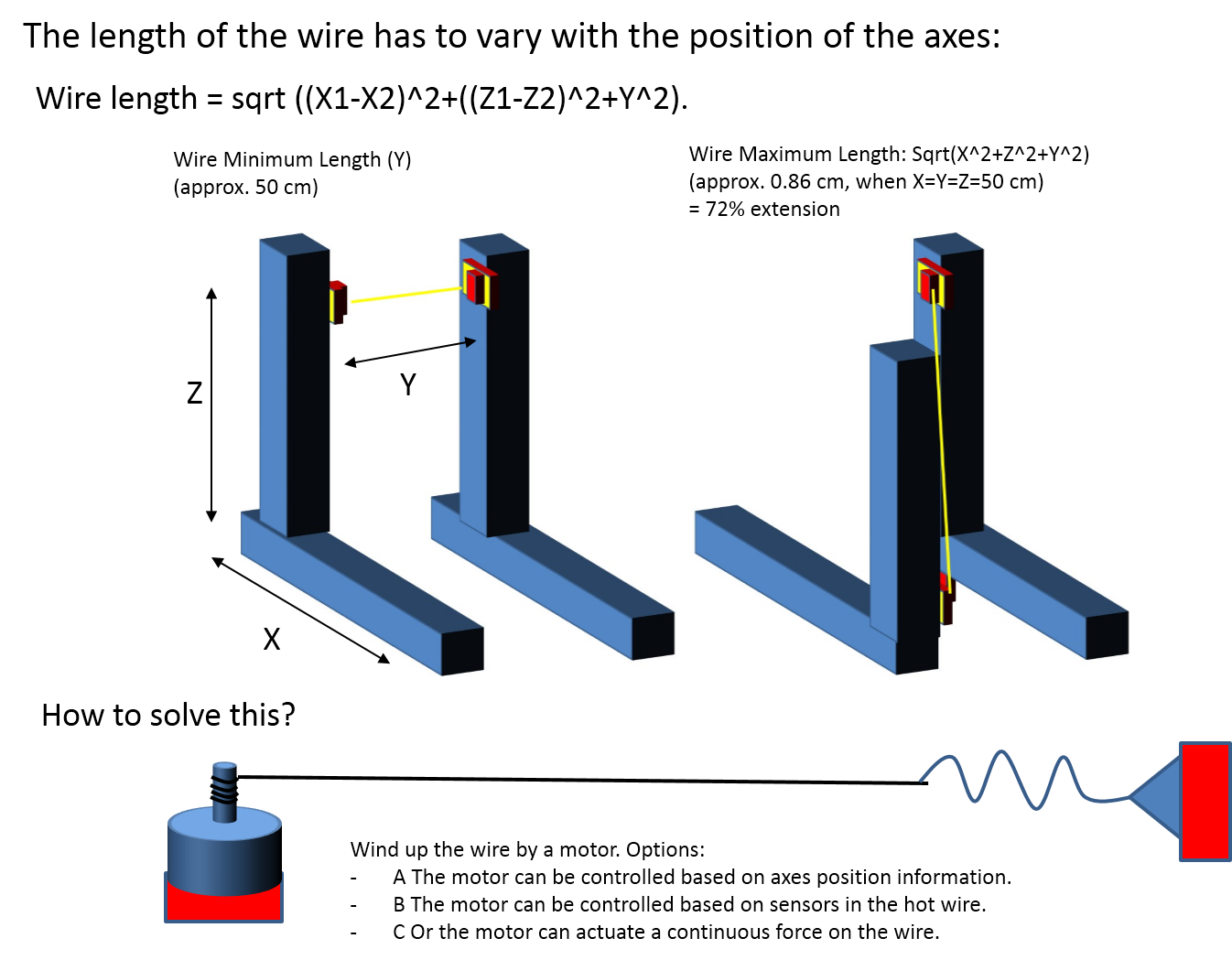
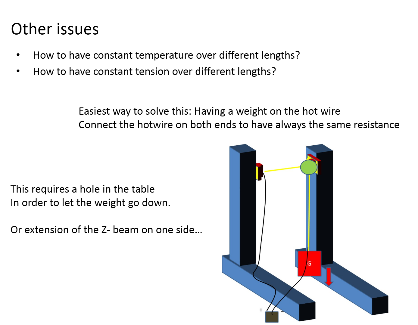
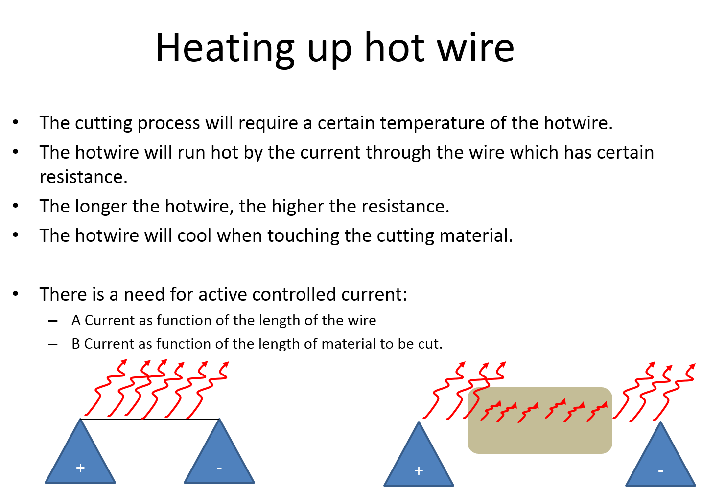
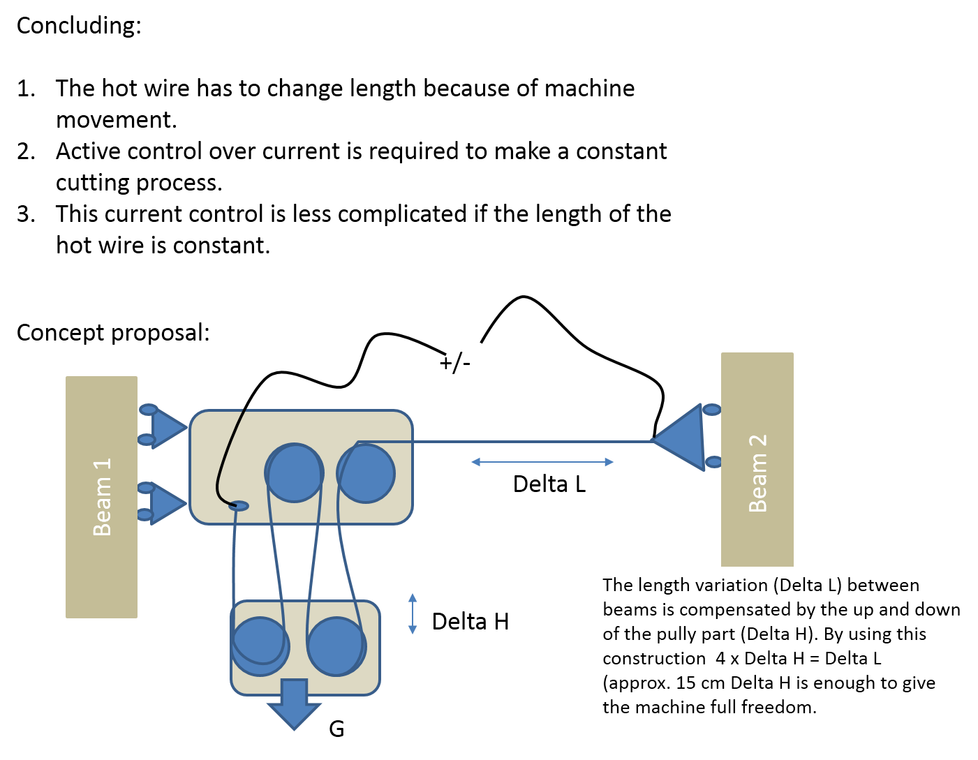
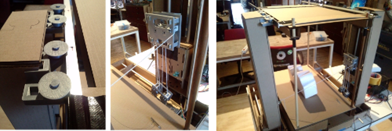
These considerations are used to generate the first concept ideas. The concept is 3D printed and shown to the team for discussion. The slider parts for the top of the Y-beams are a clear improvement. The pully system was still not completly fitting in the cardboard structure, but could explain the story quite easy.
.
Improvements
More recommendations come if concepts are realized. One of the ideas is to make the machine much more functional by adding a rotation axes. It will be an impressive task to get the right translater from STL-files towards the machine code for those 5 axes. This is beyond what we can do!
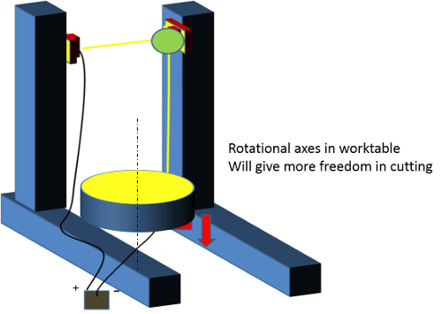
Easier improvement is to add more stability to the machine. Based on many industrial machines (like presses and milling machines), we can better start with creating more stiffness by a C-frame construction. Together with the others I have designed the dimensions for this plywood (5 mm) concept. The sketch below suggest how it has to look.
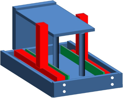
The design is created with RHINO and parts are laser cut by the new laser machine at the Waag.
The slider wheels at the top of the Y-axes are accepted and will be part of the final concept.Next to this improvement the pully concept has been accepted as idea and has to be improved for functional use. New designs have to be generated to make it fit to the system. Some thoughts lead to the idea of putting the pully wheels on top of each other. That saves space and parts. An integrated slider guide will make the pully construction more stable and less fragile. The wheels are constructed in a way that threads cannot be clamped around the axes.
Hereby the results of the improved pully concept. All parts are 3D printed with the PLA material. They click all togehter. If movement between parts are required; 0.5 mm play is designed. If parts have to be press fit, the pin and the hole are designed with the same dimension (for example 4,5 or 6 mm for both).
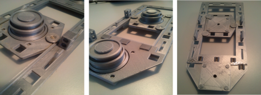
Installed on the machine; the foloowing parts are contributed by me: 1- desiged the base, 2- Designed and created the sliders on top of the Y-bearm, 3 - The pully construction.
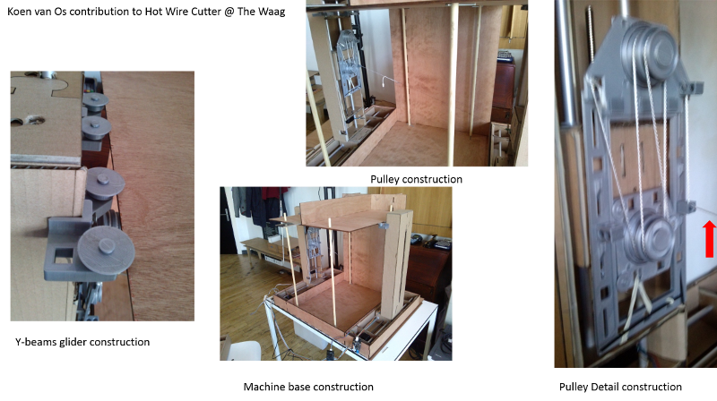
The pulley system in detail is shown below. All elements are based on the frame. The hotwire is connected to a flexible PES thread which bends easily over the wheels and glides through the thread guiders. In the top, two wheels are mounted on the same axes. The wheels are having an overlap with each other to prevent the thread slipping between wheels. The lower wheels are mounted on a slide which goes up and down. The slides is under tension by the elastic element mounted to the frame..
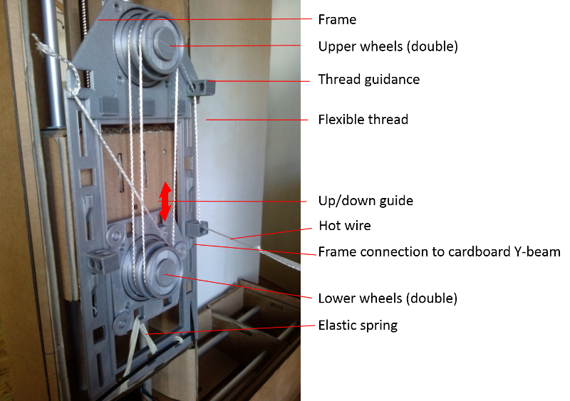
Recommendation on improvement (again...)
Improving is an never ending story. Nevertheless next steps are visible immediatly if you build the system. What I should recommend for the pully system is to redesign and bring all forces to the neutral line of the frame. Long lasting tension on plastics will deform the plastics. Especailly with the PLA. hHis material is not stable under tension and deflection can be expected over days already.
Other machines build during my FABLAB Academy
I've managed to build ULTIMAKER ORIGINAL+ from parts into a fully functional 3D printing machine! Very satisfactory job to do! I understand all elements of a 3D printer by doing like this!