
Assignment
" complete your final project, tracking your progress:
what tasks have been completed, and what tasks remain?
what has worked? what hasn't?
what questions need to be resolved?
what will happen when?
what have you learned?
documentation during development
demand- vs supply-side time management
spiral development".
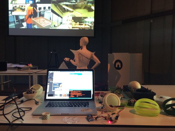
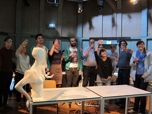
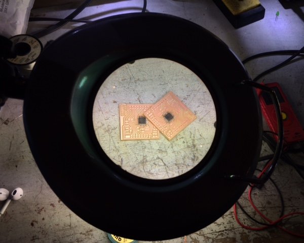
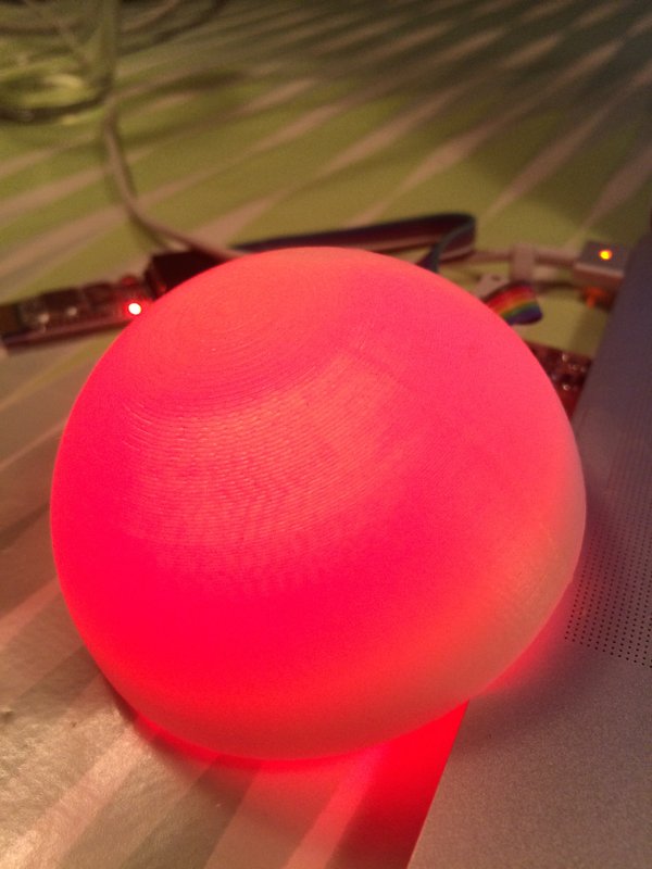
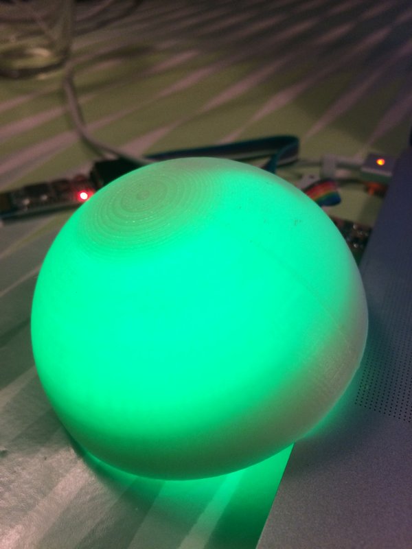
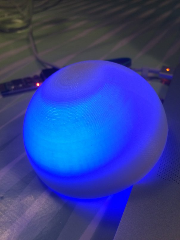
Cheers, we did it! But not just like that. The pictures pretty much sum up presentation day for me: Working to fix my project all through the previous presentations, and then making it work just in time! I suppose that's what Neil's law on time and effort is all about :)
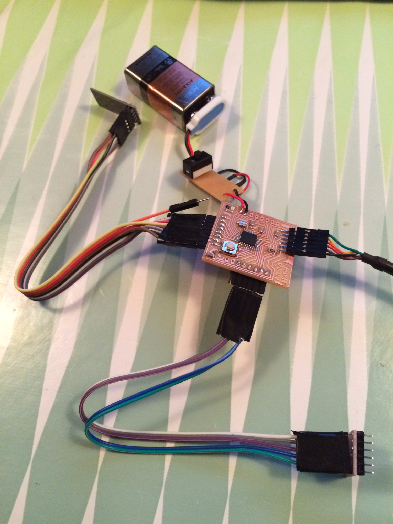
In the morning of presentation day, I took the electronics from the balls and fixed the components on two lasered clear acrylic circles that fit just behind the screw threads of the balls. Somehow though, after assembling, the radio connection was gone! The transmitter was still transmitting good accelerometer data but with a time out at the server. In serial monitor I saw that the receiver was 'listening' but not receiving data, other than a single line of rgb values. The LEDs thenselves were working fine but they didn't respond to gestures anymore. To fix this, I tried all of the following things;
All to the same or more/less the same output and conclusion. I suppose I shorted something within the ball when I turned it on.
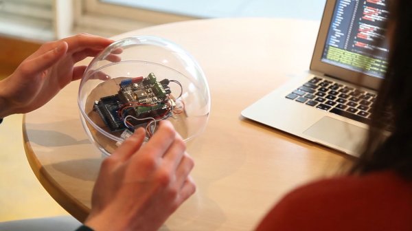
After several hours and help from Zaerc and Emma I realized that I had to make my mind up about the presentation, whether to postpone it or to go ahead. I decided to go ahead and show the video to Neil, as proof that I actually did it and however briefly, it worked. I also wanted to try to make the balls at least do something; such as control their own leds with their own accelerometers, like I did before. Less interesting, but well still something! I was programming and testing that until just before my turn which was rather unnerving; turned the switch, closed the balls, stretched the cover over it and luckily it still worked!
After presentation, we had an excellent and much needed bbq at Alex's to unwind and say thanks. I can't believe it's over! Thanks for the wonderful ride everyone.
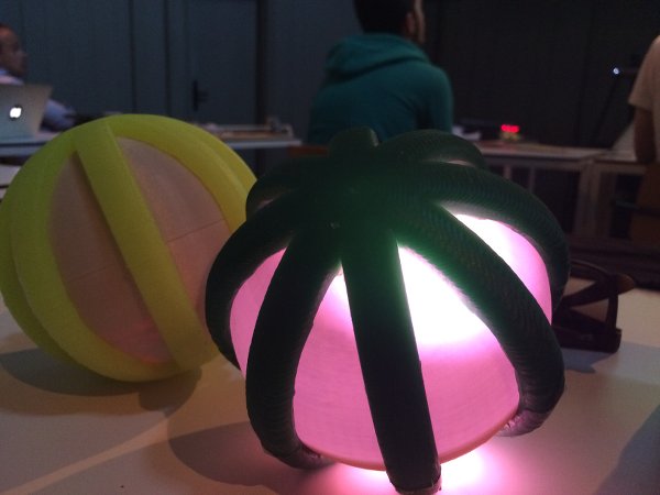
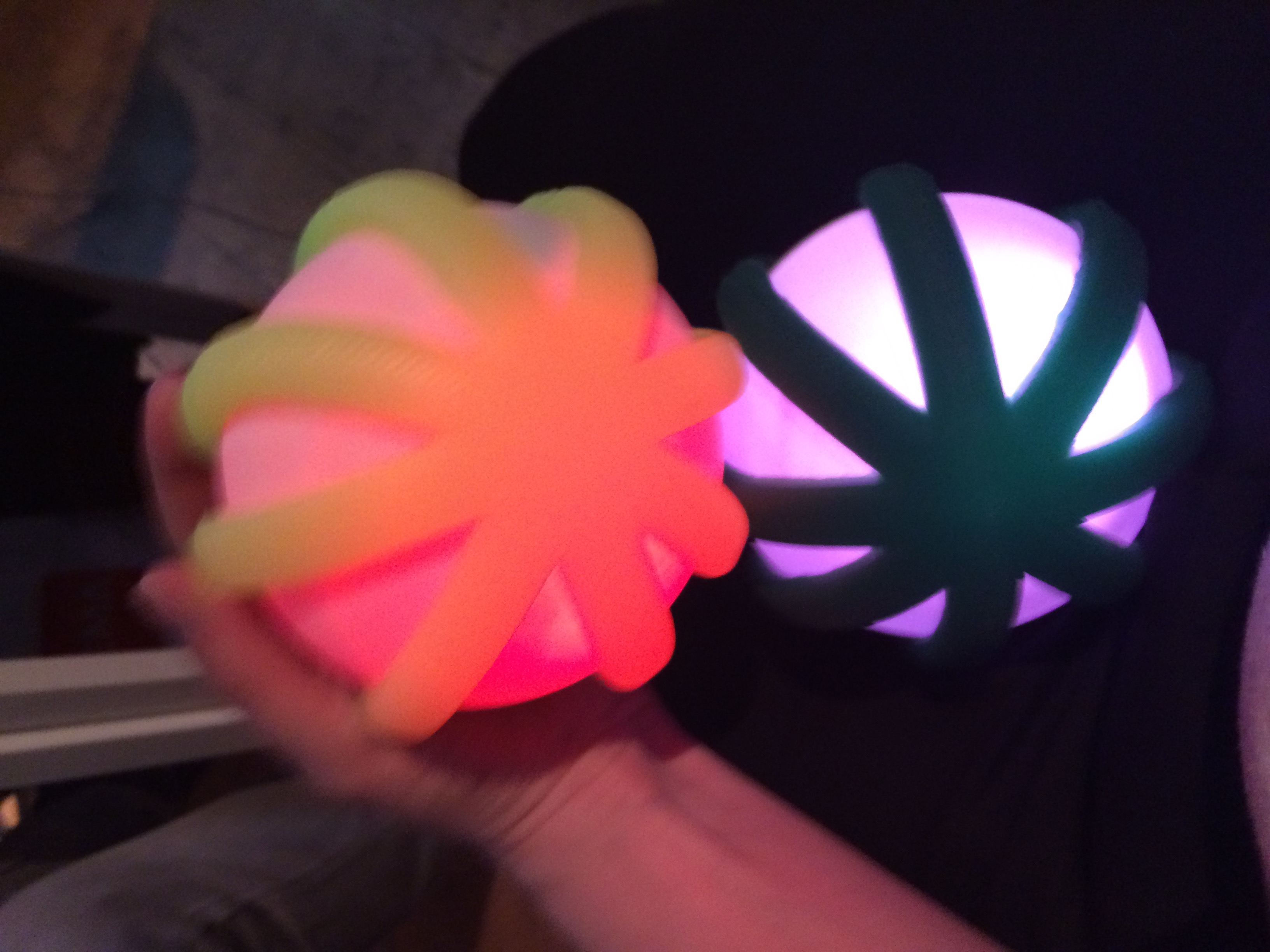
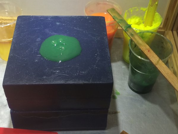
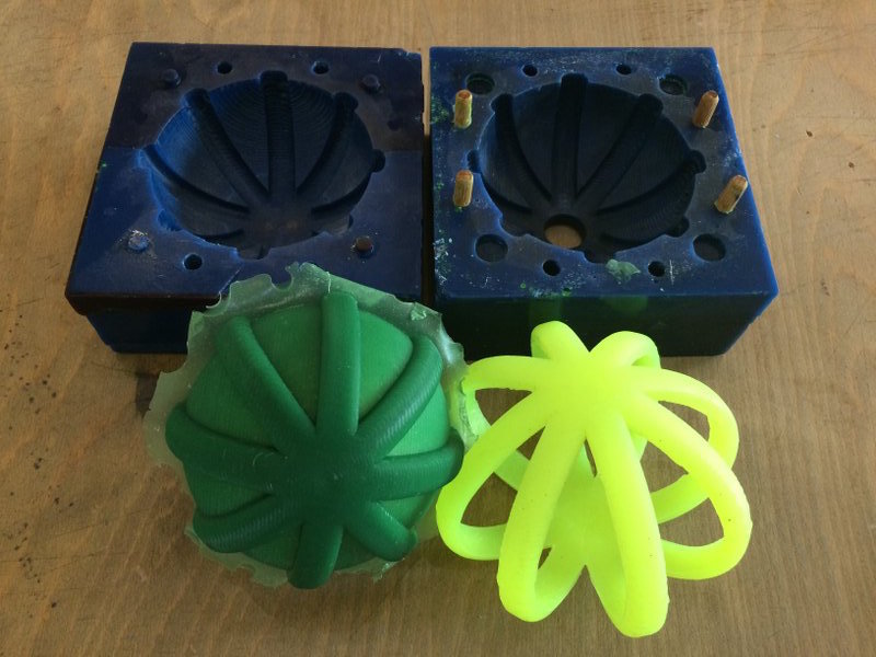
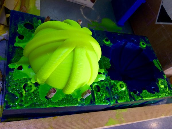
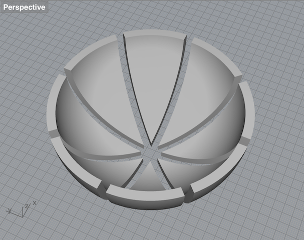
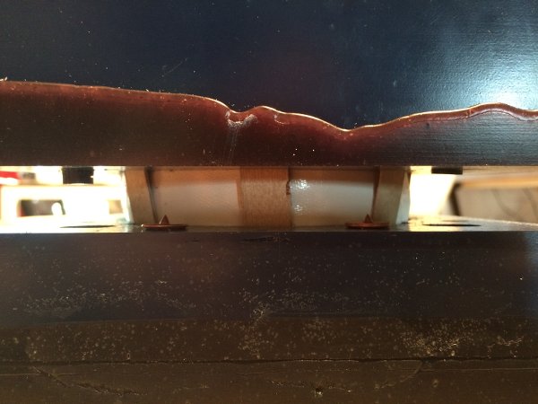
..................................................................................................................................................................................June 9 / After the partly successful test cast, I got new silicone and dye and made the first final cast which I unmolded without taking any pictures whatsoever. That says a lot about my state of mind in those final days, but it was great. A big bouncy jellyfish that (after cutting away the excess silicone, fit my balls nicely for protection. They are flexible enough to be removed and strong - the weakest points ofcourse are bubbles, which luckily I hardly had any of. At the day of the presentation I unmolded the second final cover. A bit too dark green, but still translucent with hte LEDs behind it. This assignment has gone wrong in so many ways but it also got back to its feet everytime, often better even :)
 ..................................................................................................................................................................................
June 7 / Another plan B! Seeing that there are only three days left to final presentation, I decided (and was coached :) to focus on programming the interaction between LEDs and accelerometer and getting the radio connection to work. So at least for now I'd leave the vibrating speaker and the two-way communication out of the mix. Also, something surprising happened; Burning the bootloader worked for one Fabduino, but not for the other. After several hours of troubleshooting I decided to use an Arduino Uno with my breakout boards in one of the balls and the working Fabduino in the other, to get on with programming.
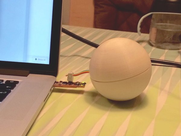
June 8 / I managed to control an RGB led coherently with the accelerometer data on the Arduino Uno, see the short video below. Here's the Arduino code I used for that.
Earlier, I tried to do this on the Fabduino but the accelerometer data I got was fluctuating all the way, making it impossible to map and translate to rgb values.
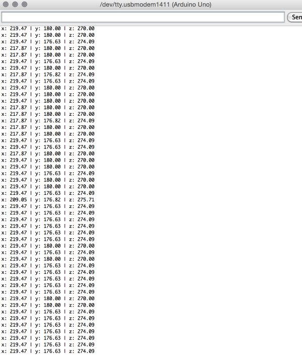
Here’s what I'm seeing in serial monitor with the ACCELEROMETER NOT MOVING, on FABDUINO (left screenshot, accelerometer vcc and gnd connected to my 9v-3.3v breakout board, the breakout board to a 9v battery, the other three accelerometer pins to the fabduino, ftid cable for the serial read.) And on ARDUINO UNO (right picture, accelerometer VCC connected to 3.3V on Arduino).
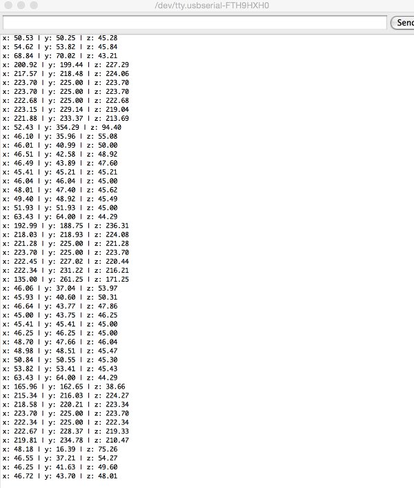
As always, troubleshooting takes time but I did find the cure: changing the battery :) I powered up the Fabduino with a fresh battery, stuffed everything inside my ball and started rolling and playing with it. A useful test, as I noticed that;
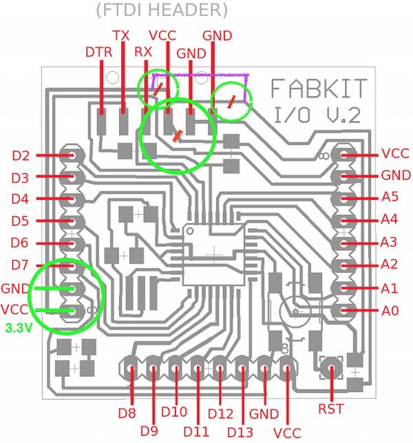
Zaerc taught me a simple trick how to fix (read: molest) the Fabduino so it doesn’t take 5v from the FTDI cable and is powered through battery/regulator with 3.3v alone. Earlier, I already changed the regulators on the breakout boards from 5V to 3.3V. The radio as well as the accelerometer might otherwise get damaged. We scratched and rerouted the traces leading from VCC in the FTDI header to the board.
In the mean time, I also unmolded my silicone cover-test, which turned out half really good! I tried cutting away the excess silicone in between the ‘threads’ and that was very easy. the second half of the cast was bad, still soft. i guess the last bit of ‘part b’ that was left in the flask had residue or something. anyway - I'll go by the Form-X store in the morning to pick up more silicone to make the two final casts I need. I also
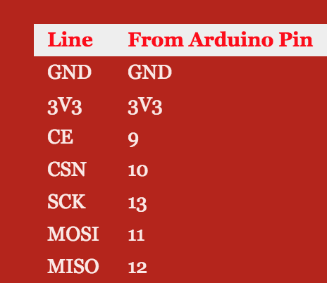
With the help of the NRF24I01 tutorials below, and Emma and Zaerc, I managed to create a radio connection between the two radio modules by afternoon.
maniacbug on getting started with the rf24,
this library from github,
tronixstuff on arduino and the spi bus
and
nRF24L01 2.4GHz Radio/Wireless Transceivers How-To.

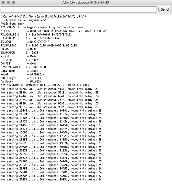
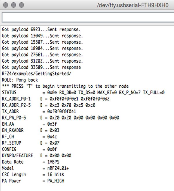
I first tested using this example code that was using the Arduino RF24 library, and communication was there (a ping and a response time). I made/assembled a transmitter and receiver sketch that is sending and printing the accelerometer data, but it gave me problems compiling and I didn't manage to fix it. Emma then suggested I tried the Mirf library instead. Using Mirf we also managed to get a successful payload sent, see screenshot on the right. Using this sketch I eventually managed to successfully send a message as well as a number.
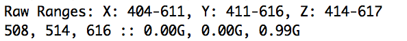
June 9 / A long night later, with lots of help from Zaerc, I got working: sending accelerometer data over radio, mapping it to rgb values that control the leds on the second microcontroller board. Amazing. To get the right values out, I found an excellent adafruit sketch with which to calibrate the accelerometer, since the range of numbers that could be sent was too wide and the effect in changing rgb colors too little. I arrived at this range;
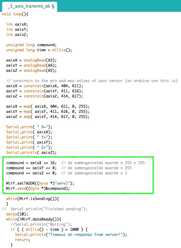
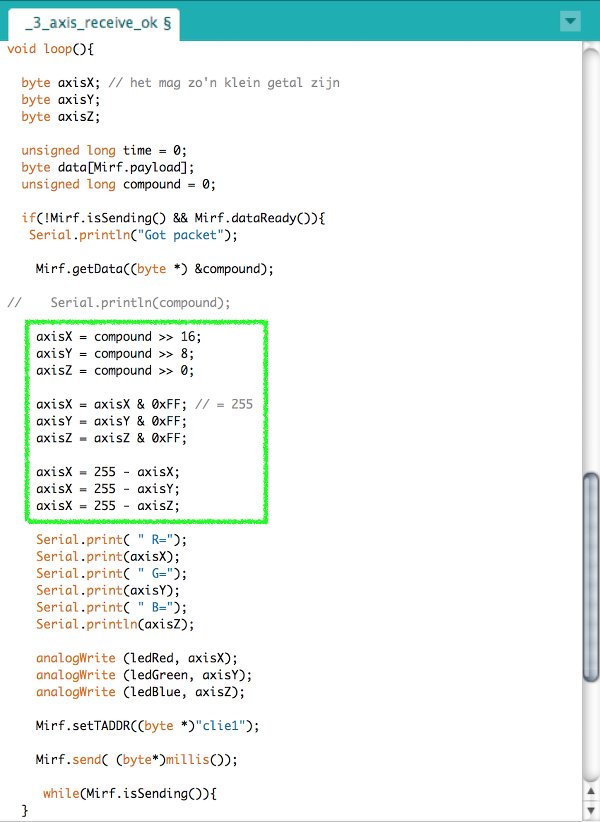
Coding together with Zaerc, I learned a couple of excellent tricks, such as how useful it is to have the serial monitor of the transmitting ball already print the mapped RGB values of the leds, instead of just the accelerometer data. But most of all, how to use math in order to be able to send three values within one byte. Basically by shifting the comma and thus multiplying each value by a multiple of 255 before adding them into one compound value that is sent over to the other radio module. The receiver sketch shifts the comma again and divides the compound to get the seperate values. I highlighted the code in the exerpts below here:
I assembled the balls and tested them, made this video of the working prototype, and went to bed a happy girl :)
Resources
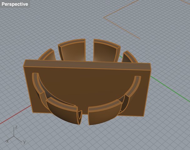
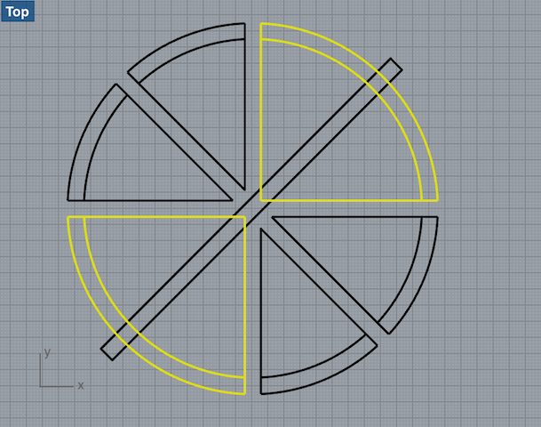
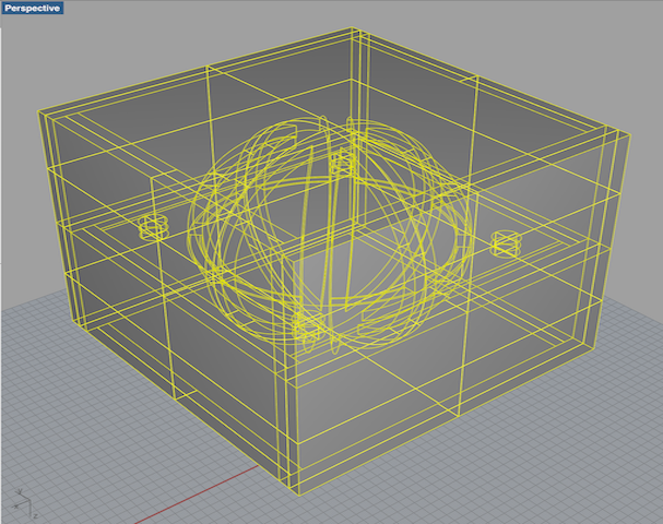
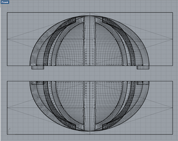
During this part of the assignment I really noticed how much I've improved in the art of Rhinoceros. In one afternoon I designed the mold for the two silicone ball covers. Not a commercial speed still, but great though! It obviously helped that this time I wasn't designing a mold for a mold, since the wax mold alone would be good enough to cast the silicone rubber.
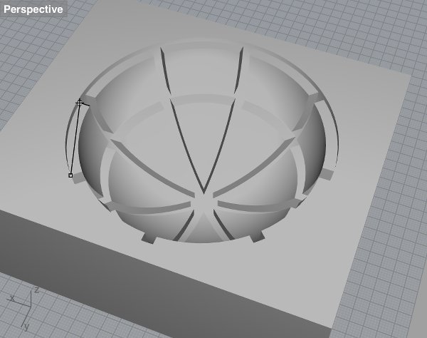
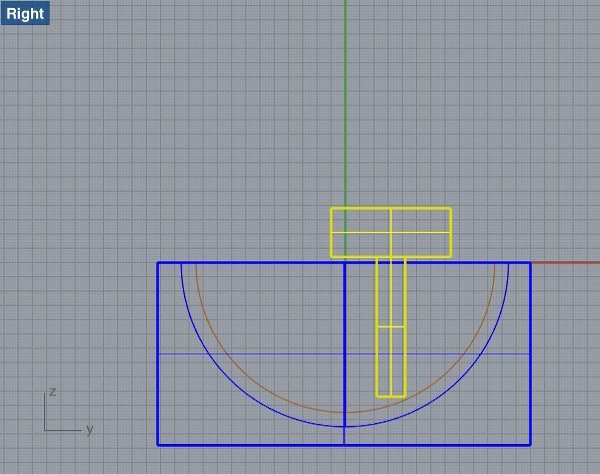
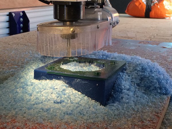
As you can see above, I measured to make sure the ball would never touch the ground when dropped and (nice tip from Joe) measured to make sure the end mill and collet would not run into the ide of the mold when milling.
Shopbot settings for the rough job;
Shopbot settings for the fine job;
OR SO I THOUGHT. Turns out that in the software I forgot to actively set the end mill size for the fine job, assuming that it would be the same as the rough one, unless you change it. But it wasn't - the fine job was milled with a 1/4" end mill in mind, which is 6.35mm. The machine actually had a 10mm bit, so I saw basically every hole was milled bigger and I realized my mistake. Now the situation was that I had already melted all scrap pieces of wax in the lab to make these two blocks for my mold, and there was basically not enough time to remelt and cool this piece and also have enough time to do one test and two casts that each take 24 hours to cure.
I realized that the biggest problem would be that the keys and holes I designed in the mold would not fit anymore. The fact that tha ball-hole was slightly bigger was no problem since I could easily cut away excess silicone. I discussed this within the lab and our brilliant volunteer Ruud came up with an elegant solution which I decided to try. So: I also milled the other part of the mold with the faulty settings, so that they would at least be the same.
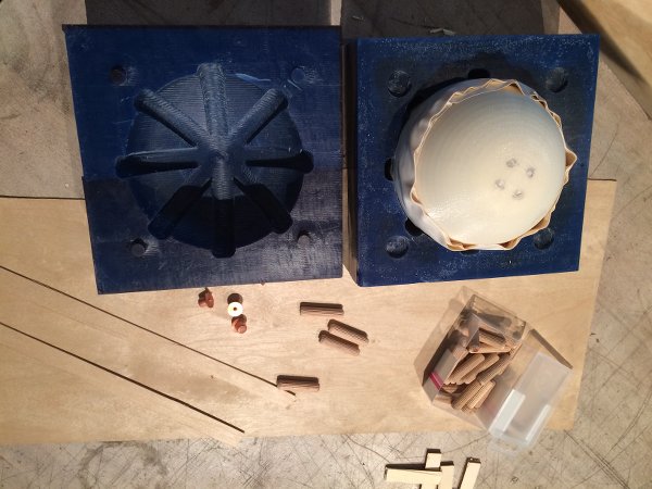
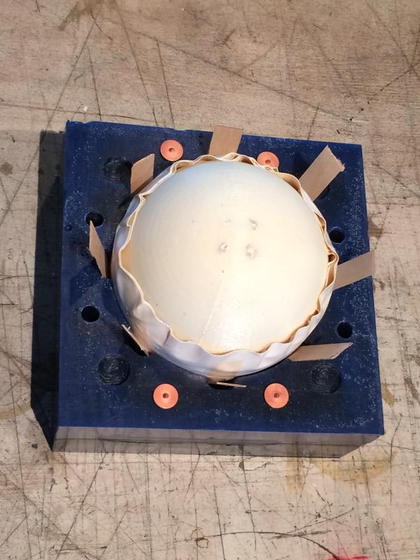
To determine the place of the new keys I placed one of my balls inside the mold and wrapped it in tape so that it would fit tightly. I lasered a bunch of thin, flexible pieces of wood the size of the 'threads' of my mold, drilled new holes in the bottom mold and placed pointy pegs in them, that would leave a mark on the other side, and carefully placed the top mold on it. Then I drilled holes where I saw the marks and placed wooden pegs in them to function as the new keys. With that done, I hand drilled a large pouring hole in the top mold and made a first test-cast of the silicone that was left from my casting assignment. It turned out to be not enough, but since it was a test cast (I wanted more transparant material for the final casts) I didn't mind that much. Now wait 24 hrs.
Resources
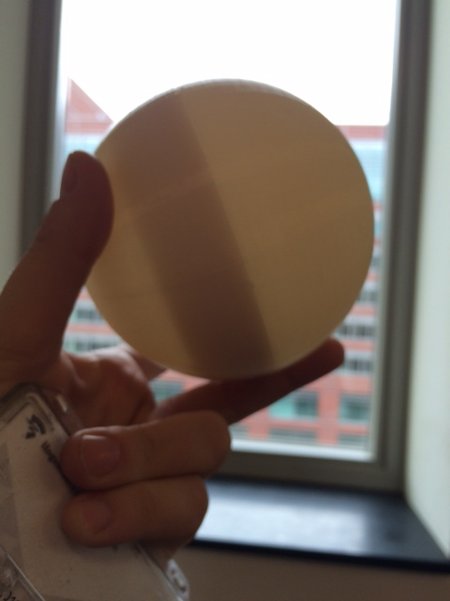
I printed a first small prototype of the balls I intended to use (two half spheres that screw together) already in the last week of April. After my failed attempts at designing my own screw threads in Rhino (see week 5), I looked for a design with screwthreads that I could adapt for my purpose. I found a really nice sphere screw box by Jamie Laing on Thingiverse, that I scaled to what I then thought would be about the right size. I printed the balls in ABS on the Dimension printer at Amsterdam University of Applied Science and started to experiment with sound, vibration and light inside the balls.
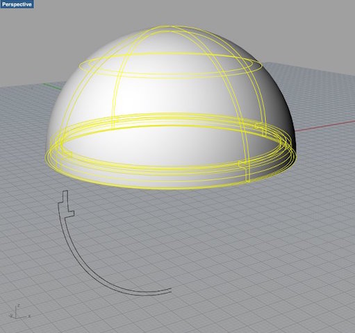
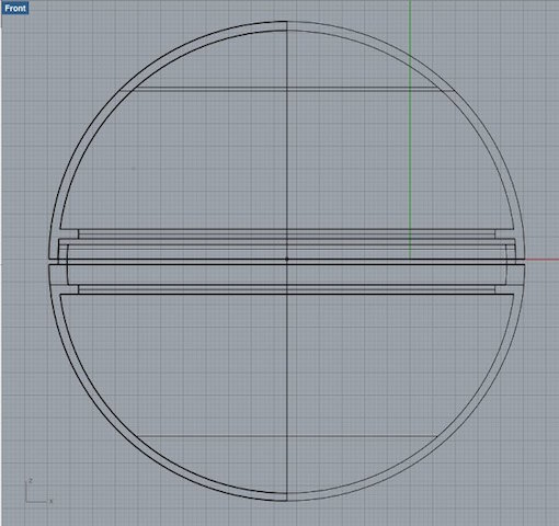
Doing this, I saw that in the way these balls were designed, the many double walls blocked the light in the tops and the sides of the ball (see left rhino screenshot below).
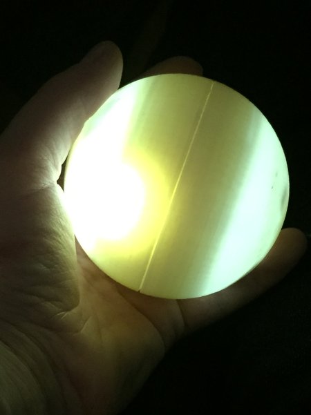
I adapted the design so that outside of the screwthreads, the ball was empty inside, with 1.5mm thin walls, which let a lot more light shine through (the middle screenshot).

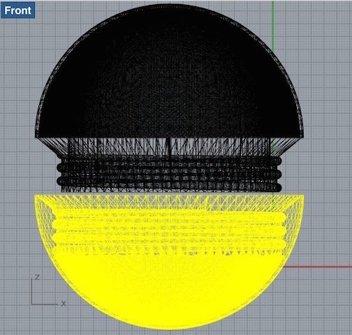
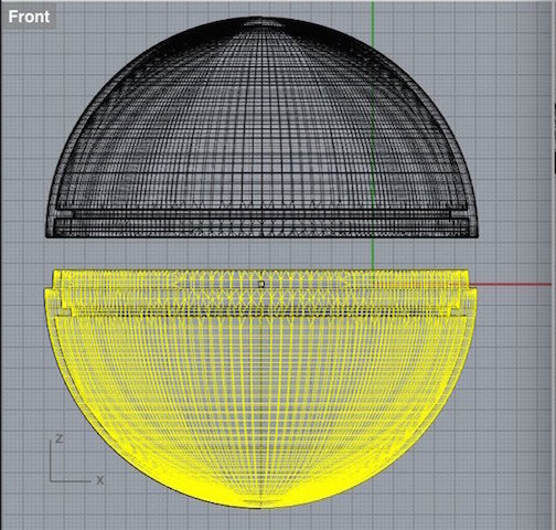
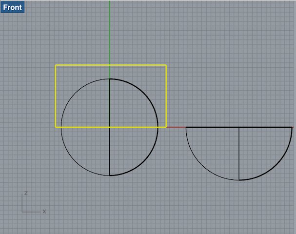
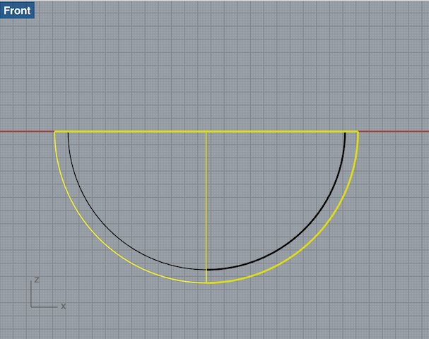
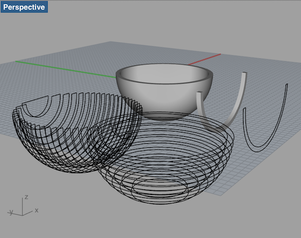
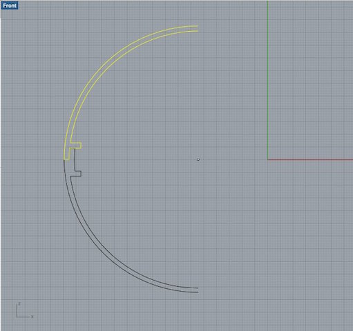
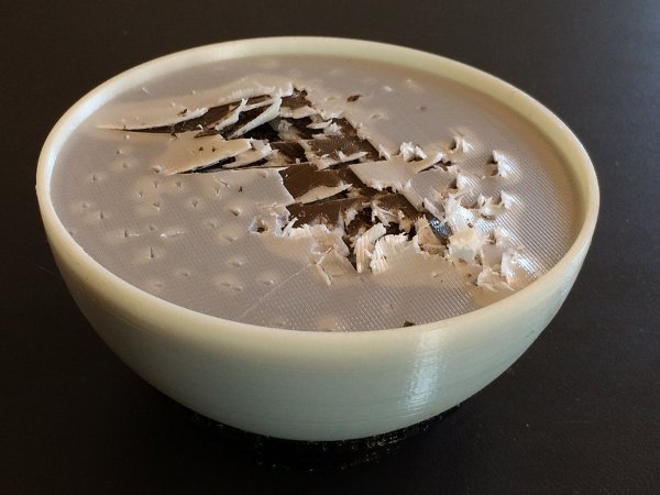
Eventually, in the last week of the project when I knew my silicone covers worked out, I started from scratch and designed a new ball without screw threads, just a thin edge that would make sure the top and bottom kept their position (right screenshot). I used a new technique though - drawing a quarter of the ball in 2d, and then using the 'revolve' command in Rhino to create a 3D shape.
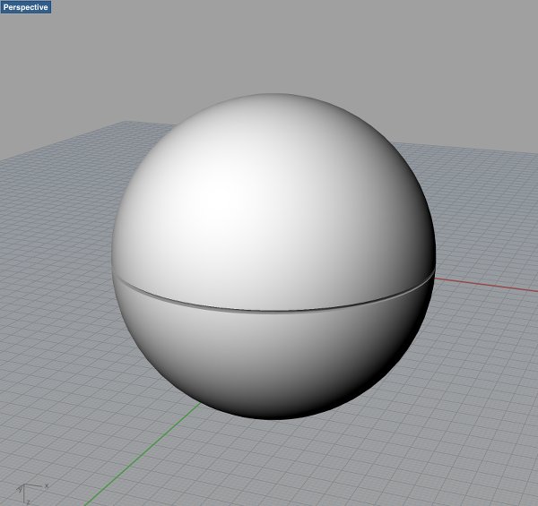
I did this for both halves, meshed them and checked the meshes in Netfabb. All looked fine. But when I removed the two halves from the printer, they were completely filled up with layers of support and ABS. I began to remove it but it was no use. Unfortunately, time was running out and I decided to go with the second (middle) version of my balls.
Resources
For each ball to be able to control the other, each ball needs at least 2 RGB leds, a speaker, an accelerometer, a radio module, a switch, voltage control and a 9V battery. I will make breakout boards to use with a Fabduino, since I need about 14 pins in total per ball. The accelerometer and the radio module come as breakout boards of their own. I decided to prepare the electronics for the most ideal situation described above here, but I do realize that programming this may take so much time that plan B is to reconsile with having one ball controlling the other over a radio connection.
| breakout boards to make | components | fabduino |
| RGB led breakout | RGB LED R: 2x 470 Ohm resistor G: 100 Ohm resistor B: 100 Ohm resistor |
6 PWM pins GND |
| speaker breakout | transistor 4 pin header 100Ohn resistor |
1 ADC pin GND VCC |
| 9V to 5V voltage regulation breakout |
switch 5V regulator 1A Schottky diode 2x 10uF capacitor 1uF capacitor |
FTDI header VCC and GND |
| existing boards |
fabduino |
| ADLX335 accelerometer | 3 analogue input pins GND VCC |
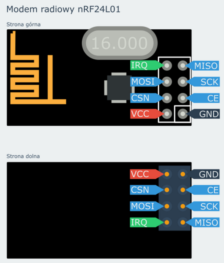
| NRF24l01 radio transceiver | 3,3V GND SCN SCK MOSI MISO (CE) (IRQ) |
| Fabkit i/o (aka Fabduino) |
Fabduino's
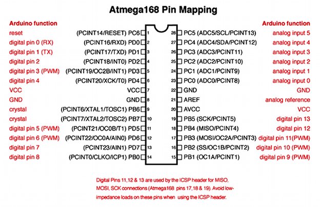
I decided to make MIT's Fabkit i/o (aka Fabduino), which has a ATmega168 microcontroller with enough pins for my purpose. This was the first time that I soldered such a many-legged, smd component. I started out in the way Neil suggested in one of the earlier lectures; soldering the pads first, then heating them up with the hot air gun while slowly lowering the component to the board with tweezers. The solder was supposed to 'grab onto' the legs and pull them in the right direction. I don't know what I did wrong exactly, but it didn't work well for me. After two attempts I found a way that suited me better - applying a bit too much solder on the legs, then removing the excess solder using the soldering iron and wick. I thoroughly tested the legs with a multimeter and found no shorts.
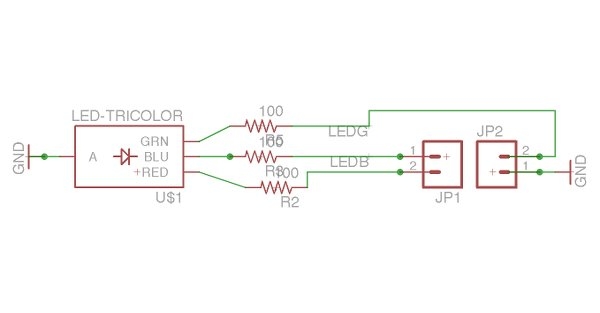
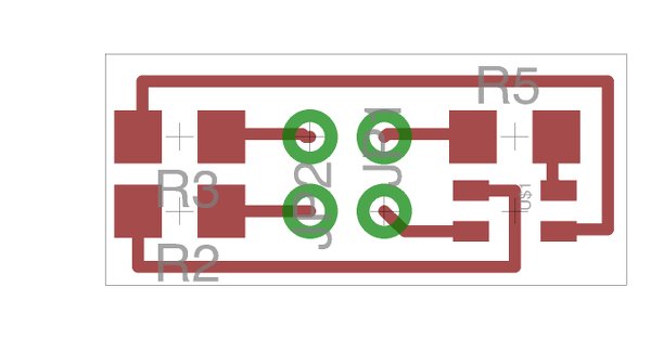
RGB breakout
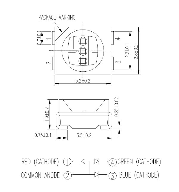
First off I checked the RGB LED datasheet from Digikey to determine the orientation of the LED and the connection of the seperate colors, and to determine forward voltage and current in order to determine the resistor values. LED current (current test) is 20mA. Forward voltage for the green and blue LEDs is 3.5V, for the red LED it's 2V. First I did the calculation for the blue and green LEDs. With a 5V supply from the Fabduino there will be 3.5V across the LEDs, so that means 1.5V across the resistor, at 20mA.
Ohms law: V = I * R
1.5 = 0.02 * R;
R(blue and green leds) = 1.5 / 0.02;
R(blue and green leds) = 75 Ohm.
For the red led there will be 2V across the LED and 3V across the resistor (5V supply, 20mA);
R(red led) = 3 / 0.02;
R(red led) = 150 Ohm.
These are the minimum values, so I decided to use a slightly higher resistance: 100 Ohm, for the green and blue LEDs and 200 for the red. Since I need the lights to be very bright I think this is enough insurance.
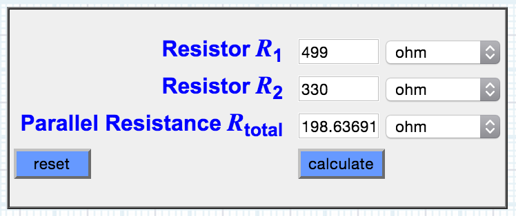
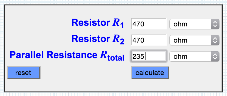
However. I designed and milled the RGB breakout boards before finding out that there is no 200 Ohm resistor in the lab inventory (about 200 ohms) wasn't available in only one component. Also, since the board was so tiny, I could't place two smaller resistors in series to solve the issue. The elegant solution now was to stack two resistors on the one pad (also cutely called 'piggyback'), and to determine their value in a parallel set up. I did that using this parallel resistance calculator. Unfortunately we were all out of a 330 Ohms resistors so I stacked two 470 Ohm ones that will deliver value of 235 Ohms. Hopefully this will not affect the brightness too much.
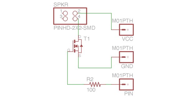
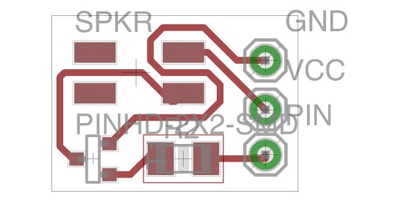
Speaker breakout
On the breakout board for the speaker I added a transistor to amplify the sound (as it will sit in a closed box) and a 100 Ohm resistor. It will be connected to VCC and ground of the Arduino.
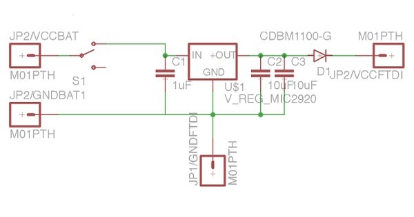
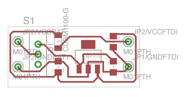
9V to 5V voltage regulating breakout
Finally, I made a voltage regulator that will allow the Fabduino to be powered by a 9V battery through the pins of the FTDI header. The board has a large on/off switch so I ca easily power off the balls if they're unused. Furthermore the board has a 5V regulator and a 1A Schottky diode on the 5 volt out-line to secure that no current will flow back into the regulator. Come to think of it now - I needed this diode when I was using a 3.3V regulator before and there was danger of 5V flowing back into the circuit via the ISP, but I guess it is less vital now. Well anyway - it's on there nonetheless :)
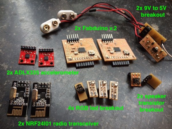
All the electronics for this assignment assembled:
Resources
1. What will it do?
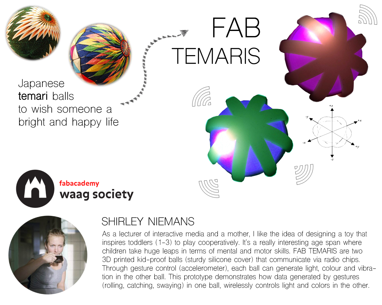
As a lecturer of interactive media and a mother, I like the idea of designing a toy that will inspire toddlers (1-3) to play cooperatively. It's a really interesting age span, in which children take huge leaps in terms of mental and motor skills. Pre-toddlers aged 1-1.5 are completely in awe of objects that produce light, sounds, colour. Motor skills are rough but shaking an object is something they usually master. Toddlers aged 2-3 have started to develop finer motor skills and are often keen to find out how stuff works.
The plan for my final project is to design and develop two kid-proof balls that communicate via radio chips. Through gesture control (accelerometer), each ball can generate light, colour and vibration in the other ball (RGB LEDs, speaker). For the youngest children, it will most likely be enough to see, feel, hear the ball that is changing color or vibrates, for the older toddlers it's possible to really find out which gesture generates which reaction, and play with that. I'm planning to 3D print the balls and add kid-proofness by designing a soft silicone cover that will keep it closed and shock-protect the electronics inside (to a certain extent).
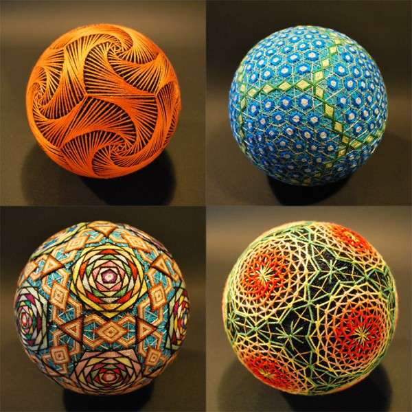
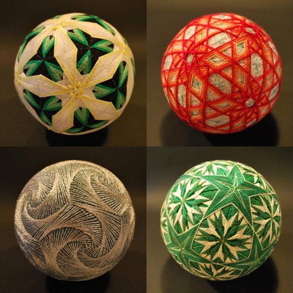
* "Temari (meaning handball), is a Japanese folk art form of embroidering balls for handball games or just plain decoration. Back in the day (around 7th century AD), the spheres were made from old kimono remnants that were wadded up into a ball and then wrapped with strips of fabric. Over time, the process of constructing one transitioned into an art form with the colors and threads meant to wish the recipient of the gift a bright and happy life." (makezine.com)
interaction scheme
At this point I'm not sure whether I'll manage to program all of this, but interaction is intended to work as described below. As long as ball 1 is being moved it is transmitting data and the ball 2 can only receive data. When ball 1 is unmoved for a certain period of time, ball 2 can start transmitting. I would like the shake movement to function as a wake up call for either of the balls to start transmission. I'm still unsure whether the transmitting ball should also light up in the same colours, or rather in a white pattern - This is something I need to test and feel the logic of.
| ball 1 | ball 2 |
| switched off no light |
no connection constant white light |
| switched on no movement |
ready for action glowing white light |
| shake wake up, start transmission |
vibrate random color flash |
| move over x axis | red colored light intensity defined by speed |
| move over y axis | green colored light intensity defined by speed |
| move over z axis | blue colored light intensity defined by speed |
2. Who's done what beforehand?
I've found (and been pointed towards; thanks Natalia, Loes!) several interesting projects online that are worth exploring for my final project. Some in terms of interaction, some in terms of hardware. None of the projects below are aimed at toddlers specifically, but I'd like to really optimize my ball game for this audience. Also, they are all one ball, communicating in most cases with an app.
MOTI http://leka.io
Moti is a robotic ball that is sensitive to its environment, moves on its own, and changes colours to emote feelings; specifically designed for children with special needs. All of its hardware and software is open souce and available on Github. Moti is made with Arduino and uses a bluetooth module to transfer data of the child's interaction with it to a server, where it gets analysed. The behaviour of the robot is then adjusted according to the child's needs. The Moti ball is quite large, about 20 cm in diameter, also - I'm guessing' to accomodate the wheels and motors that make it move around. here.
Things to learn from Moti;
I like the way the ball really invokes wonder with colors, sound and movement, even though the mechanism inside is totally visible.
HACKABALL http://www.hackaball.com/us
Hackaball is a successful 2015 Kickstarter project described as “a programmable ball for active and creative play”. The Hackaball target audience is six- to 10-year-old children who have started learning programming skills in primary school. The ball is fitted with many sensors to detect whether it’s still or moving, as well as whether it’s being dropped, bounced, kicked or shaken. Children can come up with games by modifying the ball’s behaviour through an iOS or OSX app.
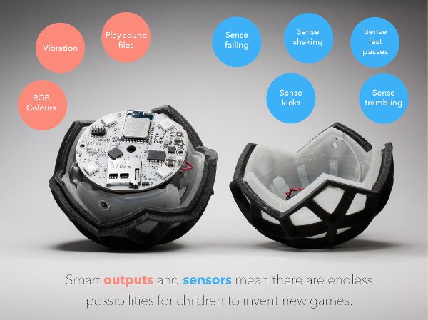
Things to learn from Hackaball;
I love the silicone 'netting' that keeps the parts together and even allows the ball to be kicked. I wouldn't go that far, but I am going to use the knowledge I gained from molding and casting to develop a flexible cover that I can stretch around the ball so that it is less vulnerable.
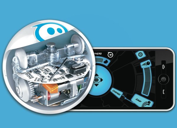
SPHEROhttp://www.gosphero.com
For both commercial products Hackaball and Sphero information on the exact technology used is hard to find. Both have enticing videos that promote the games you can play with the balls. Sphero can be remotely controlled to roll or 'drive' at 4.5 MpH. It has LEDs, is water tight, has a silicone cover and mentions a Bluetooth range of 30m. Sounds like a very cool toy for an age group a bit older than mine.
 ..................................................................................................................................................................................
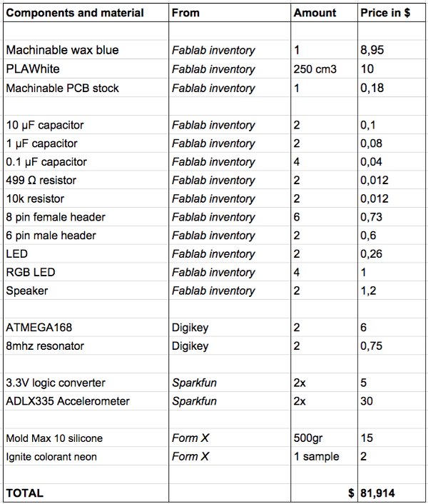
3. What materials and components will be required?
4. Where will they come from?
5. What do they cost?
 ..................................................................................................................................................................................
6. What parts and systems will be made?
7. What processes will be used?
8. What tasks need to be completed?
9. What questions need to be answered?
10. What is the schedule?
11. How will it be evaluated?
A functioning radio connection and gesture controlled light and vibration is vital for the project to facilitate cooperative play. Secondary evaluation points could be kid-proofness and the overall aesthetic value.
.................................................................................................................................................................................. .................................................................................................................................................................................. ..................................................................................................................................................................................Feb 2 / As a mother of two very young children and a teacher of interactive media, I'm challenged by the idea of designing a toy that will inspire my two kids to play cooperatively - as opposed to beside eachother. Also, at this age, they are often completely in awe of objects that emit light, sounds, colour. Thinking about a toy that could invoke cooperative play in very young children, I imagine two objects that 'know' their relative position to one another. Light, perhaps sound or colours change as the objects get closer and eventually even touch. The interaction and feedback should be simple enough for toddlers to understand that moving closer and changing position is what causes the change, and that it can be manipulated by them.
"Temari (meaning handball), is a Japanese folk art form of embroidering balls for handball games or just plain decoration. Back in the day (around 7th century AD), the spheres were made from old kimono remnants that were wadded up into a ball and then wrapped with strips of fabric. Over time, the process of constructing one transitioned into an art form with the colors and threads meant to wish the recipient of the gift a bright and happy life." (makezine.com)
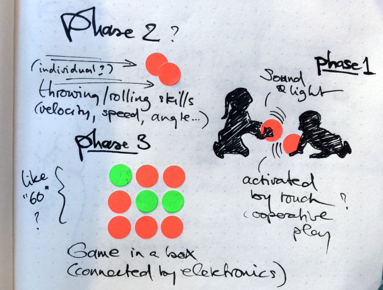
The idea of the Japanese temari as a wish for a 'bright and happy life' seems fitting to me, also because of the personal relationship Japanese tend to have with technology. I was initially thinking of the objects as boxes, but recently I realised that the interaction as well as the in and output can be programmed to evolve with the childs age. For now I came up with three 'phases' of the objects and the interaction that is possible with them;
Phase 1: Toddlers - cooperative play, wonder, experimentation. Two beautifully decorated wooden balls that emit patterns of sound and light depending on their distance to one another. The balls might be touch-activated, or have multiple touch-sensors that allow for cooperative play with one ball, too, and for other outcomes with two balls touching eachother. Beacons perhaps to sense distance from eachother?
Phase 2: Age 4-8 (?) - motor skills. A recent Kickstarter campaign features smart basketballs, that could track a players dribble, throwing speed, arc... this technology might be implemented in the fab temari-balls and used for skill-games, such as throwing a curve, rolling towards eachother, accuracy... perhaps with an app to determine who has won.
Phase 3: Age 8-12 (?) - mind skills. Let's imagine a larger set of - say - 9 fab temaris in a box that are connected by an electronic grid, position can be measured, logged. Kids can play board games with it (that still have to be designed - tic-tac-toe-like games but more challenging and fitting to their age.
Questions
Ofcourse, this idea is in its infant state, not tested against reality at all yet. I'm very curious as to how it will evolve in the coming months. Pragmatic questions I can think of to tackle are; Which sensors are relevant, what texture, material should the balls be made of, how to make them kid proof and kid safe, how small can they be, how to make toddlers understand intuitively what to do, can they be touch-activated...

This work is licensed under a Creative Commons Attribution-NonCommercial-ShareAlike 4.0 International License.