
Assignments
"read a microcontroller data sheet, program your board to do something, with as many different programming languages and programming environments as possible".
Reading the datasheet
March 15 / The data sheet of the Atmel Attiny 24, 44 and 84A processors is a 286 page document of technical details, some of which will come in handy for this week's assignment.
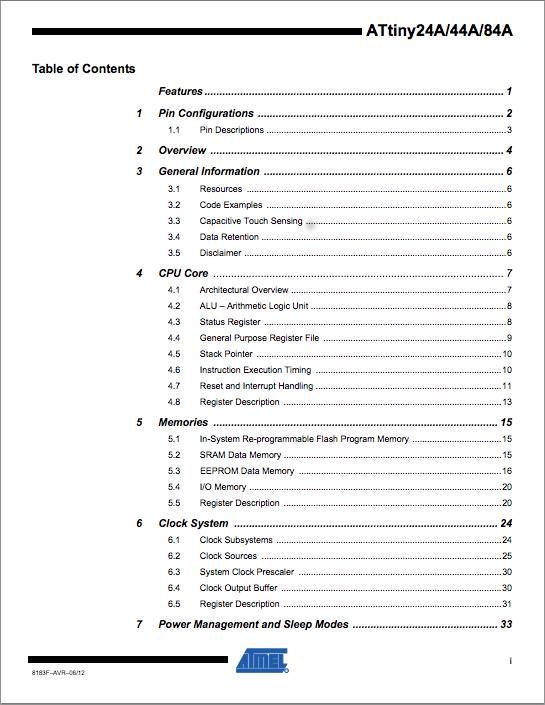
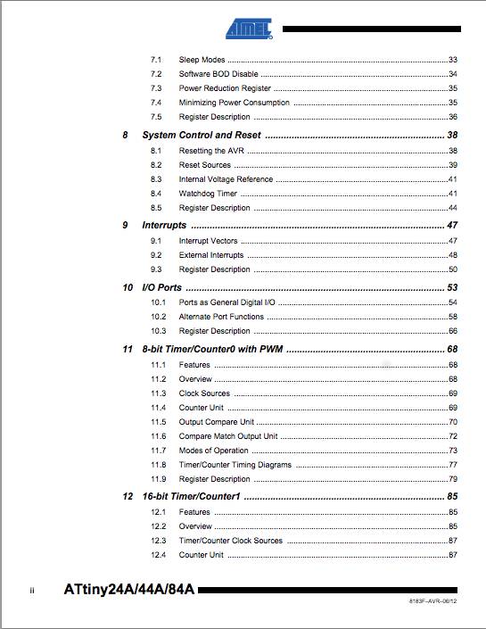
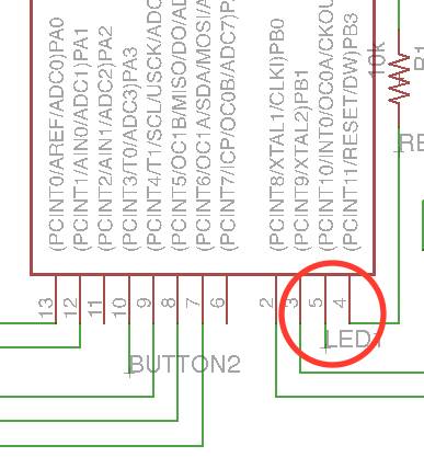
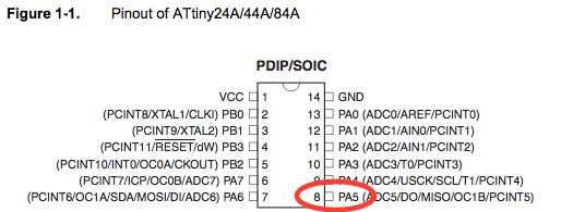
Several pieces of important data (that appeal to my current level of experience that is) are given right in the beginning of the document, among which: the pin configuration and pin functions such as ADC, PWM etc. In order to program the processor and blink a LED using the Arduino IDE, the correct pin number of that LED should be used. Unfortunately this is not the same number that we find in our schematics. I've tried to understand why this is the case, and how I might otherwise use logic to determine the right pin number, but Emma stopped me there and advised me to just accept it. In my case, it looks like this. In the schematic, I see that the LED is connected to pin 5. In the pinout from the Atmel datasheet, I see that this corresponds with pin 8 on the actual microcontroller. And so 8 will be the pinnumber I need for my first sketches in Arduino IDE - as you will see below.
I was surprised to notice that a simple blink sketch already takes up 25% of the tiny44's program storage space, which is only 4 bytes, or 8 in the tiny84 - will that be enough for my final project? But then again, C code is supposed to be much 'lighter' than Arduino code. Also, I tried to understand from the data sheet why the internal 8mhz clock is often bypassed by an external crystal, but I didn't find the answer there, rather more questions. At least now I have an overview of what is in the sheet and I will know where to look.
..................................................................................................................................................................................Programming the helloEcho board
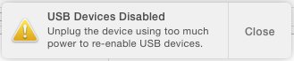
March 15 / Today I connected my Hello Echo board to the ISP (in system programmer) that I made in week 4. Following the excellent highlowtech tutorial, I updated my Arduino software to the latest version and added the Github library for the attiny44 microprocessor to the Arduino IDE sketchbook. I selected the 'attiny' board, the 'attiny44' processor and the usb port. Next, I uploaded the 'Blink' sketch to the board, saw a puff of smoke and smelt something burn. Then my Mac said;
Troubleshooting #1
March 16 / I'm at the Fablab now, debugging and trying to find out why my device is using too much power. On stackexchange, I found the default amount of current that a USB port will deliver, which is 100mA. Since we know that a USB port supplies a voltage of 5V to a device, this equals 500mW power. Before diving into these calculations, I decided to check all my physical solder joints first. This proved to be a good call as I found several mistakes. The most interesting one was this;
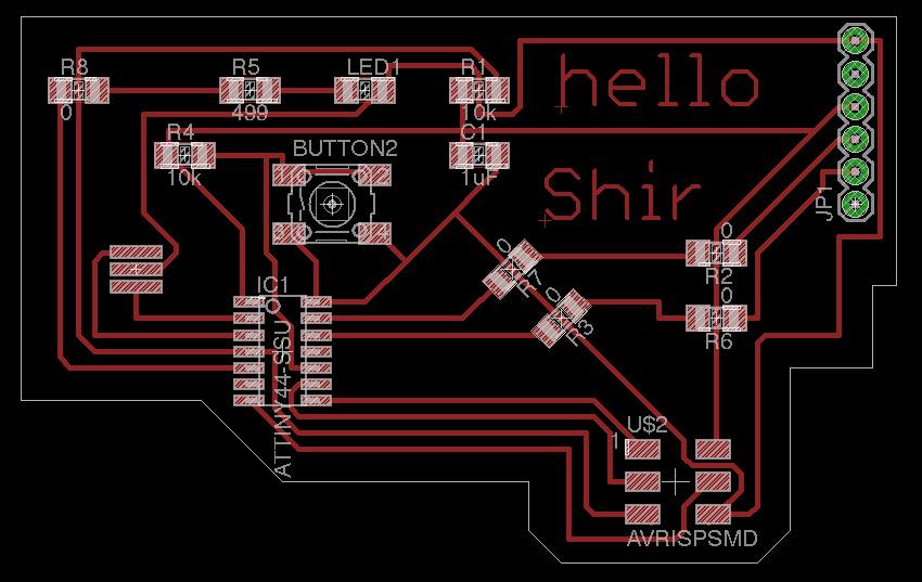
When making the .png file in Eagle for milling the traces on the helloEcho board, I forgot to add the layer 'pads', so the green circles that you see on the right side of the board (this is the footprint of the 6-pin header) did not get milled. That made it hard to solder the header to the board correctly, but impossible to solder a trace running beneath the header (Ground) to pin 1. After talking to Emma I found another place to connect Ground to pin one - with one of my beloved 0Ohm risistor bridges. Worked like a charm.
Troubleshooting #2
After checking with a multimeter that each and every connection on the board was soldered well, I connected the board and ISP to my MacBook, opened Arduino and tried to run the Blink sketch again. This time, it returned an error;
Then Loes proposed I use her ISP to check whether uploading the sketch would work. And it did so immediately. However, my ISP was also able to upload sketches to Loes' helloEcho board, via her laptop. Emma then tried several different combinations of laptops, boards and ISPs and suggested I replace the ISP's microcontroller. I will do so, but for now I'm using Emma's ISP to be able to continue with the assignment.
March 17 / Using the borrowed ISP, I managed to get the Arduino blink sketch working, and after that also the button sketch. However, the actual button pretty much did the opposite of what I told it to do.
 ..................................................................................................................................................................................
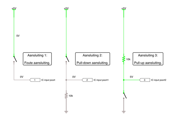
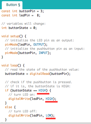
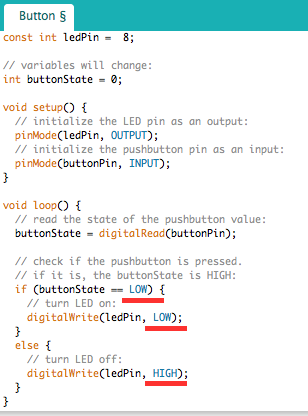
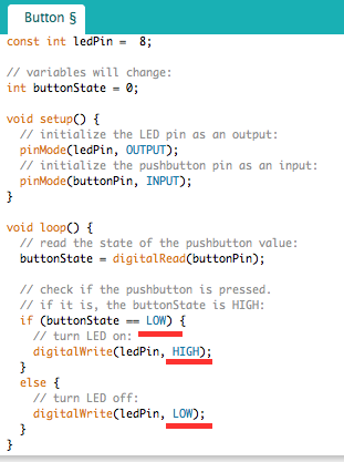
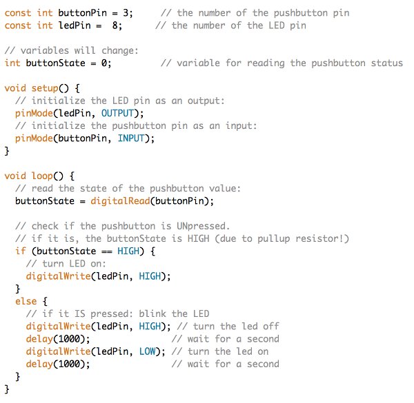
With the button unpressed, the LED was on, when I pressed the button, the LED went off. Although I liked the counter intuitiveness of it, I wanted to understand what happened. I found a topic on the Arduino Forum explaining that the wiring of the the button could cause this. If it has a pull-up resistor (a resistor connected between the button and VCC) the normal buttonstate would be HIGH (=unpressed) and low when pressed. I checked and this is actually the case on my board. I found this article on the pull-up risistor quite comprehensive. It is in Dutch though.
Lastly, I combined the blink and button code examples so that the light is on (HIGH) when the button is NOT pressed, but it starts to blink when it is pressed, and goes back to the contant-on state when released. Find executable code under 'resources'.
Programming in C
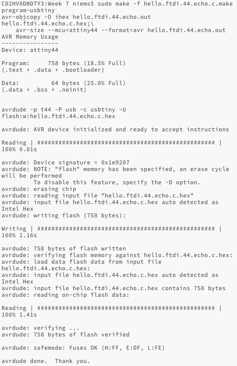
I downloaded the hello.ftdi.44.echo.c and the hello.ftdi.44.echo.c.make files that Neil points out in his C tutorial. I then ran sudo make -f hello.ftdi.44.echo.c.make program-usbtiny in terminal and got the right response.
However, when I opened the serial monitor in Arduino IDE to check whether the board was echo'ing my input, it did not return anything. Checked baud rate, but that was correct. Since programming in C is not required (but nice!) and time has run out for this week, I decided to leave it for now and come back to programming C later on.
..................................................................................................................................................................................Resources