
Assignment
"make the FabISP in-circuit programmer".
Feb 19 / The week started off early, with Waag Society's strong black coffee and a lecture on milling and soldering circuit boards by Emma Pareschi. Somewhere in the next couple of weeks we will learn to design our own circuit boards and program a micro-controller. To do that, we will need an in-system programmer (ISP), which is what we will be making today. The workflow will look something like this;
Choosing type of ISP
Within the Fablab community a couple of Fab-ISP designs have been made with slightly different properties, as (very) crudely drawn below. For elaborate specifics per maker, please see David A. Mellis, Andy Bardagjy and Valentin Heun.
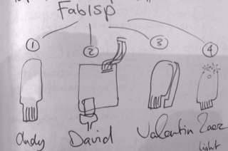
Aside from these three options, Waag Society's own Zaerc has also made an ISP: the FabTiny*ISP. Among other things, this ISP has a reset button and a set of LEDs that let you know when a program is running, and when the board is connected to power. Both these features as well as the fact that we like to support (and get support from) Zaerc, we all chose his design to work out today.
 ..................................................................................................................................................................................
Milling traces on the Roland Modela
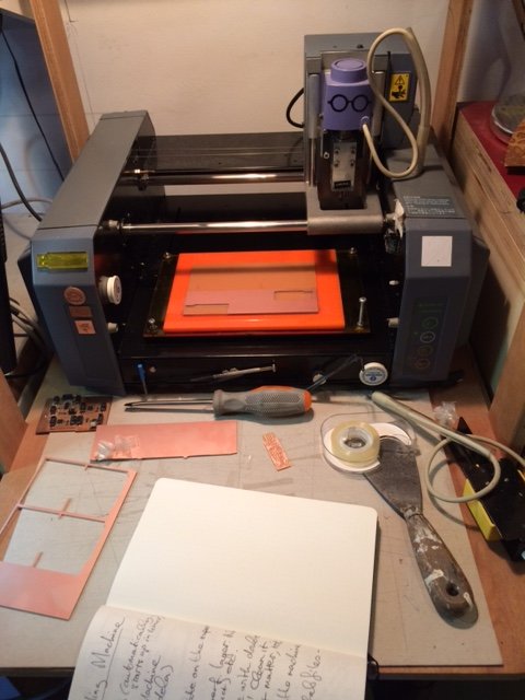
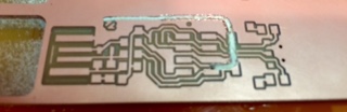
After Emma's explanation of the workings of the machine and software, I got to work on milling the traces of Zaercs design in copper (a copper coated FR1 plate) and then cutting out the board.
After giving in the origin points for the endmill (X, Y), I used the setting 0.1 for Z, which meant that I would be milling 0.1 mm deep. Halfway through, I paused the machine to take a look at the plate. The carved traces looked shiny, indicating that the mill didn't cut through the layer of copper completely.
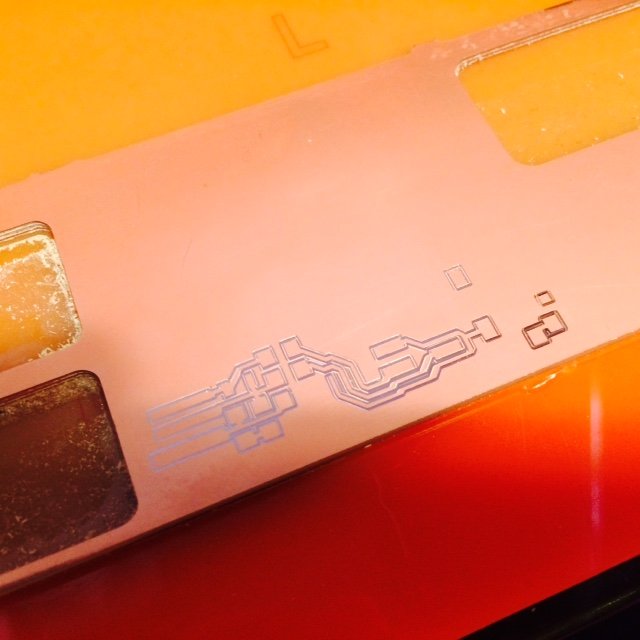
I did three more runs while gradually cranking up the Z value from 1 to 1.5mm, 1.5 to 2mm and finally even to 2.5mm, while - to my complete puzzlement - the copper stayed shiny and the machine seemed not to respond to the new values. Emma then pointed out that after each change of value I should select "make .path" again (as well as make .rml and send it - which I both did), or the machine will not get the new information. One less mystery! The next run - Z on 1.5mm again - the traces came out beautifully. Next step: Cutting out the board.
Cutting out the board
I now swapped endmills - 0.4mm is for carving and 0.8mm for cutting out - carefully minding to not screw it tight but "just snug", as Neil Gerschenfeld was clear to point out during his lecture this wednesday. I loaded the new .png, changed the values, made a new path and .rml and sent it to the Modela. Right after it went to work however, the machine made a terrible sound. The endmill suddenly turned from its path and cut right through my carefully milled traces. I paused the machine (knowing I broke it) and noticed that the endmill had come loose from the machine and was now stuck in the copper plate. With help from Emma I pried it loose and saw confirmed that my circuit board was ruined. Fortunately, the Modela still lived. So then I screwed the endmill in *real tight* and started off milling new traces and - succesfully this time - cutting the board out.
 ..................................................................................................................................................................................
Soldering
With the shiny new board in my pocket, Emma gave soldering instructions. I did some soldering many years ago - although never with parts this small - and liked it, so I was keen on getting into it again. I practised for a bit on a spare board and then set out to solder a microcontroller on mine. I learned how putting a tiny blob of solder on the place where you want the device to be makes it much easier to get it done without making a mess - tweezer with the tiny device in one hand and soldering iron in the other, heating up the blob and the device simultaneously. After that first step, you can let go of the tweezers and hold a piece of solder instead, to connect the other side of the device to the copper. It took a while but I managed to solder the whole board pretty neatly. Or so I thought, until Neil pointed out in the global review that my solder joints were not shiny, which in theory could affect the flow of current to and from the components.
Testing the board
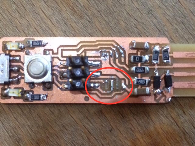
After soldering one each element I tested with a multi meter to see if it was correctly connected. This is why I didn't suspect anything to be wrong when I inserted the board into my Macbook USB port. Upon inserting though, I saw a puff of smoke and the LED indicating 'power' did not light up. Testing with the multimeter again did not solve the mystery, but careful comparison to the FabTiny*-layout did - I missed one capacitor! To be sure I replaced the LEDs and then I soldered the capacitor on. Now, both light came on - a state that shouldn't even be possible, and it even puzzled Zaerc for a while. Zaerc tested whether his laptop recognized the board, and it didn't. I tested each element with the multimeter again, but it all seemed connected. I almost gave up when Emma noticed that the microcontrolled was soldered on the wrong way around. It didn't occur to me until then that it was a directional element, but OFCOURSE it is! By now, it was the end of the day. Emma advised me to resolder it tomorrow, but I was so stoked on having a functional ISP TODAY that I went to work right away. Soldering a new microcontroller in between all the other elements was very difficult though. I messed up the solder and removed it again, but - frustrated and inpatient by now - I used a tiny bit of force and took part of the copper trace off with it. Ruined another board. Then, I went home.
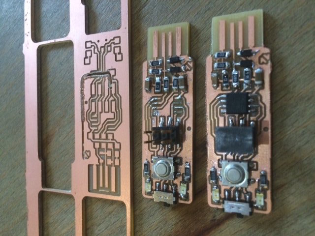
Making a new board
Feb 20 / Refreshed, I arrived at the Fablab this morning and milled, cut and soldered a new board in 2 hours! All good things come in threes - as we say in the Netherlands :)
 ..................................................................................................................................................................................
Programming the ISP
Feb 23 / Emma sent us a tutorial on how to program the FabTiny*ISP, using an Arduino as an ISP. I have an Arduino Uno at home, so I will try to do it myself today.
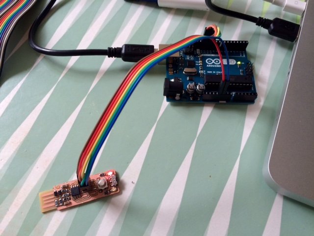
I connected the FabTiny*ISP to the Arduino. I didn't have a six-pin connector so I connected the Tiny* with separate wires according to the schema in Zaercs tutorial. I downloaded and installed the AVRDUDE software, the XCode developerspack and upgraded to the latest version of the Arduino software. Then I downloaded the firmware for the Tiny*, uploaded the ArduinoISP sketch to the Arduino and closed Arduino ISP. Finally... time to check if the board I made really works! I ran the command for programming the fuses, but got this error:
C02HV0DNDTY3:~ niems$ avrdude -c usbtiny -p t45 -V -U lfuse:w:0xe1:m -U hfuse:w:0xdd:m -U efuse:w:0xff:m
avrdude: Error: Could not find USBtiny device (0x1781/0xc9f)
avrdude done. Thank you.
C02HV0DNDTY3:~ niems$
I checked the solder joints, connections, cables, they seem to be allright. Tried it again with the switch flipped but that gave the same result. I then emailed Zaerc and explained the issue.
Feb 24 / It turned out to be a small mistake in the tutorial - the port wasn't specified correctly, a quick fix after which I could succesfully program the fuses. Soon after however, I ran into another problem which (consulting Zaerc) was fixed by adding and deleting a hashtag in the makefile. Step by slow step, I feel I'm reaching the end of the tutorial and the beginning of my life with FabTiny*ISP. One of the final steps is checking whether the computer recognizes the USBTiny device, by running the "lsusb" command mentioned in the tutorial. Unfortunately, this command doesn't exist in MacOSX, nor in Windows 8.1. Using a workaround that I found online: "system_profiler SPUSBDataType", I can get a list of USB-connected devices, but I can't detect the USBTiny in there. I will talk to Zaerc and Emma about that tomorrow at De Waag.
Today I tested the visibility of the ISP on Ubuntu, and also there it's not detected. On Emma's advice, I reprogrammed the device using a TinyUSB ISP instead of my Arduino. Again, all steps gave the correct response, but again, a "lsusb" command on Ubunto didn't show the device. Finally, on Emma's advice I replaced the microcontroller. That fixed it! Now I have a very precious, working ISP. I will try to make a box for it in class next week.
..................................................................................................................................................................................Some conclusions
This has been my most succesful week in terms of failure. I've learned tons, due to making tons of mistakes. Not the fastest way to get to the finish but I do think I have a deeper understanding and much less fear of dealing with the inner workings of a/my computer. With hindsight I can say that the loss of my laptop in week 1 and the problems I've had with getting the spare laptop to function, have also positively added to that understanding.
Resources