Conductive Spinning Frame, part of the Refil Project
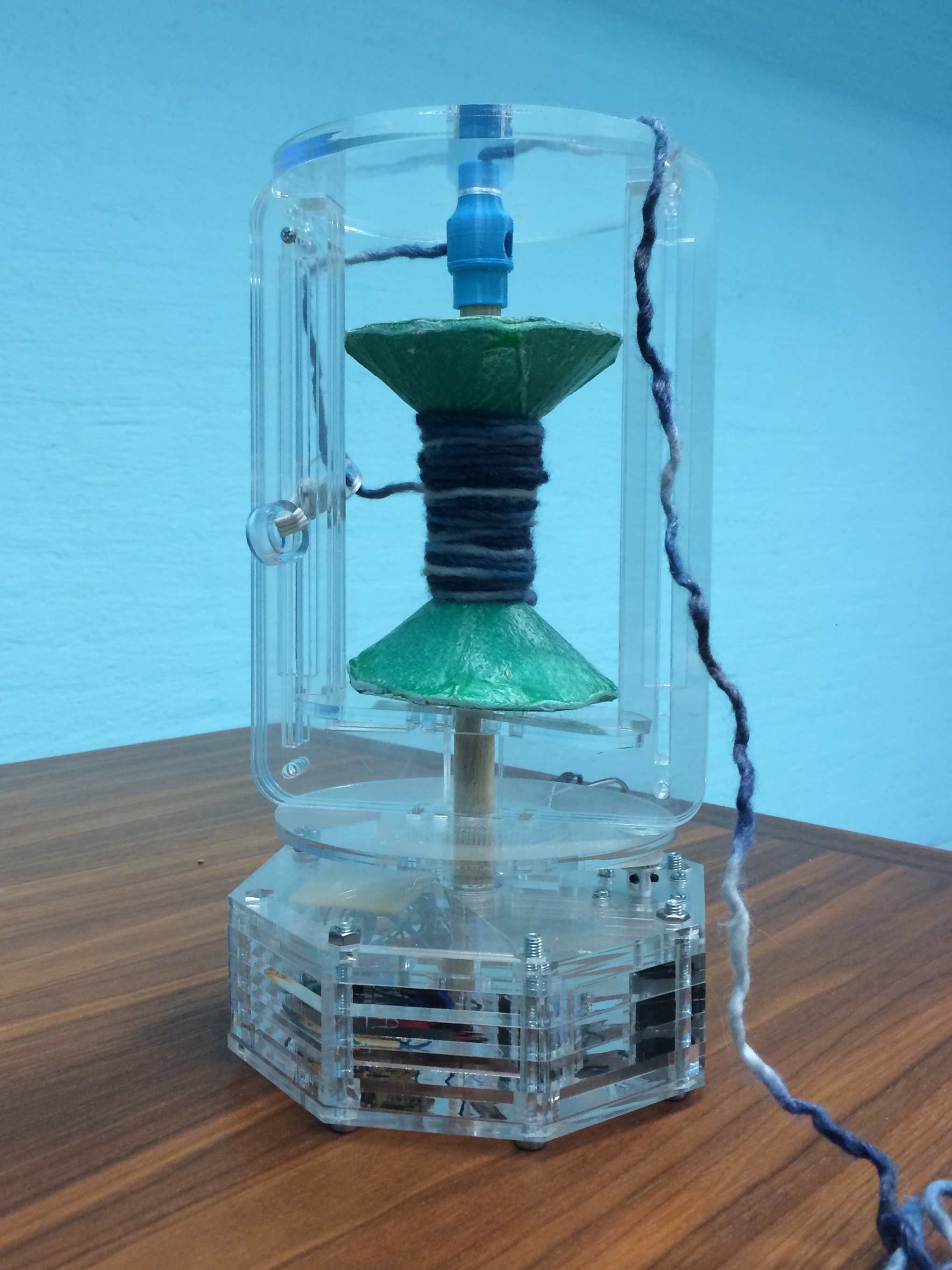
The Conductive Spinning Frame is used for the creation of spun/plyed yarns with varying amounts of twist along the yarn/ply to allow for the creation of pressure sensitive conductive “soft spots” when using conductive fiber such as Bekinox W12/18 by Bekaert.
With the Conductive Spinning Frame a user can twist fibers or ply already spun yarns including core spun yarns in a dynamic controlled manner that allows for the creation of sensor yarns that can be woven or knitted into clothes.

Conductive Spinning Frame by Troy Nachtigall is licensed under a Creative Commons Attribution-NonCommercial-ShareAlike 4.0 International License.
Based on a work at http://troykyo.github.io/Final.html.
The Conductive Spinning Frame requires the following materials:
- Acrylic 5mm 400mm x 700mm
- Acrylic 10mm 400mm x 700mm
- 15mm Wooden Dowel (38 cm)
- 20mm Tube (30 cm)
- Foam Insulation for Milling (80mm x 220mm x 50mm)
- Cotton Jersey (I used an old Apple T-shirt)
- Composite Release Film
- Composite Felt
- Composite Fiber Glass Cloth
- Composite Bag and Tape
- Thermochromic Pigment (not required, but totally awesome)
- M6 50mm Nut and Bolt x 8
- M3 16mm bolt x 4
- M3 30mm Bolt x 2
- GT2 Timing Pulley Gear
- Attiny44
- Hair Scrunchy
- Various Wire
- 35mm Stepper Motor
- Copper Circuit Board for milling
- Cable
- LM2940IMP–5.0/NOPB | Low Dropout Voltage Regulator, 1A, 5 V,
- 12v 1A Power Supply
- Filaflex 3D Printing Filament
- PLA Filament for Printing As the project develops updates are available from the Github Repository. Version 1 files are solidified for perpetuity in the Fab Academy Archive: Conductive Spinning Frame Source Files
Assembly
Here is what I did to put the Mark 1 together: 1. Laser cut the Frame Body 5mm and Frame Body 10mm in acrylic and All of the soft materials. 2. Cut the dowel to 48 mm and tube to 30mm using a Dremel 3. 3D print the Fiber Port in rigid Material. 4. 3D Print the G2 Timing Belt and Feet in Filaflex 5. Mill the Bobbin Ends 6. Lay up the Bobbin Ends and the soft materials with Composite Resin and place in Vacuum bag for the required amount of time (Follow the instructions for your resin of choice. I use Epoxy Resins Glue System | Bio Resin | Epoxy Adhesive in the hope they are a little more ecological). 7. Mill the Traces and Outlines 8. Set the fuses and program the board. 9. Assemble the Housing 10. Start Spinning
If you’re interested in making your own GT2 Timing Belt the Illustrator Brush I use is available here.
Final Project Plan
Conductive Spinning Wheel as a part of the Refil Project.
The original project plan proved to be to exspensive (700$+ in Pin board) and to much of a time commitment. Fiore helped me select one part to complete for Fab Academy; the Conductive spinning wheel. Unlike traditional wheels, this one will be controlled dynamically with a stepper motor.
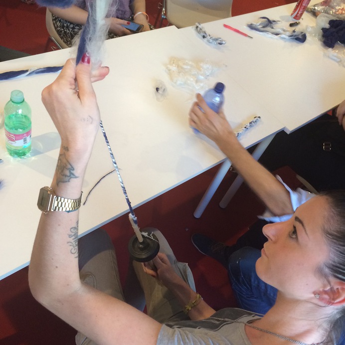
Last year at Maker Faire Rome I taught a course on Hand Spinning Conductive yarn. This Conductive Yarn Spinner will speed up the process and create dynamic control of twirl to control conductivity.
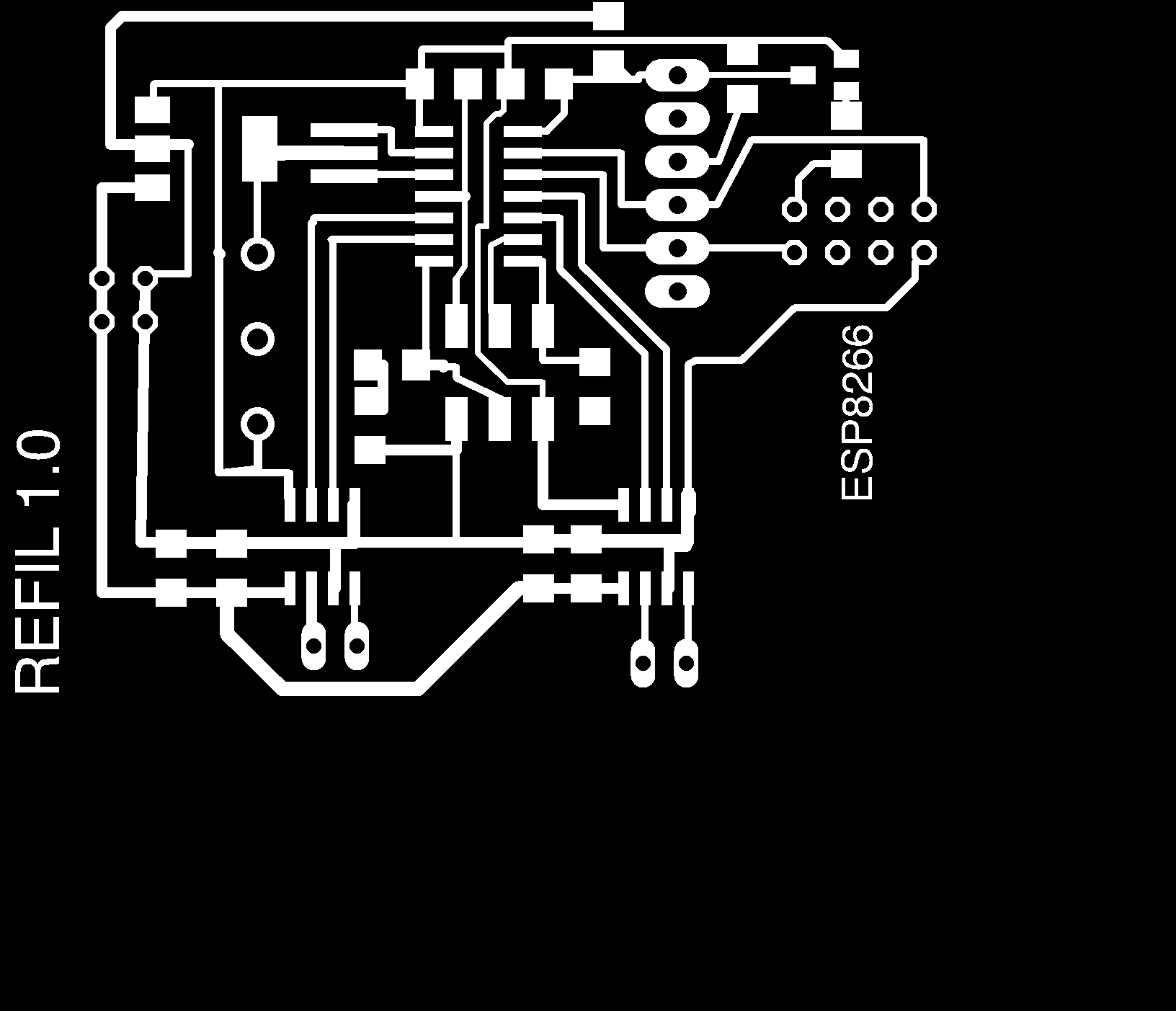
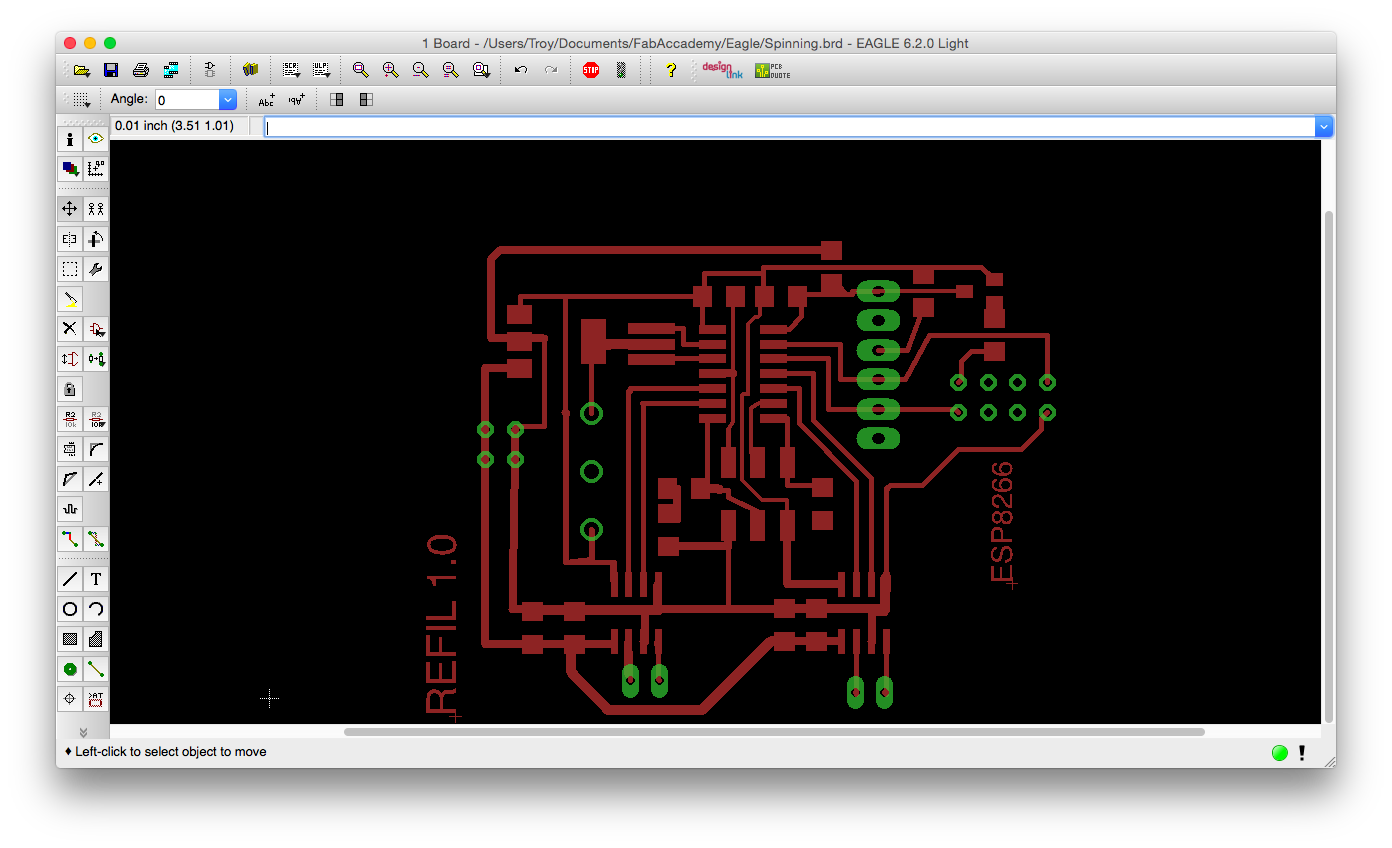
Electronics
I’ve learned to start with the hard part first so this week I am creating the electronics. I am designing the board in Eagle although the Stepper control board is not available. I found something similar and remapped the pins.

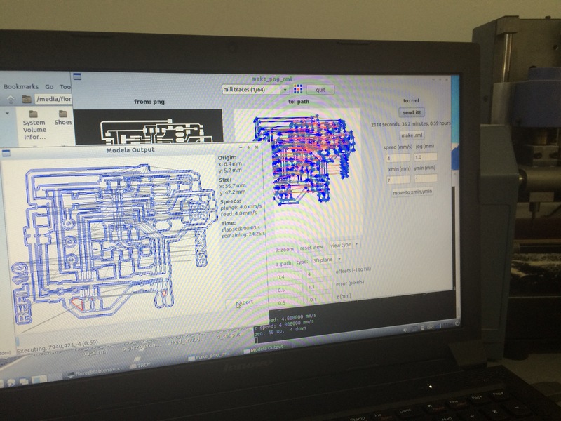
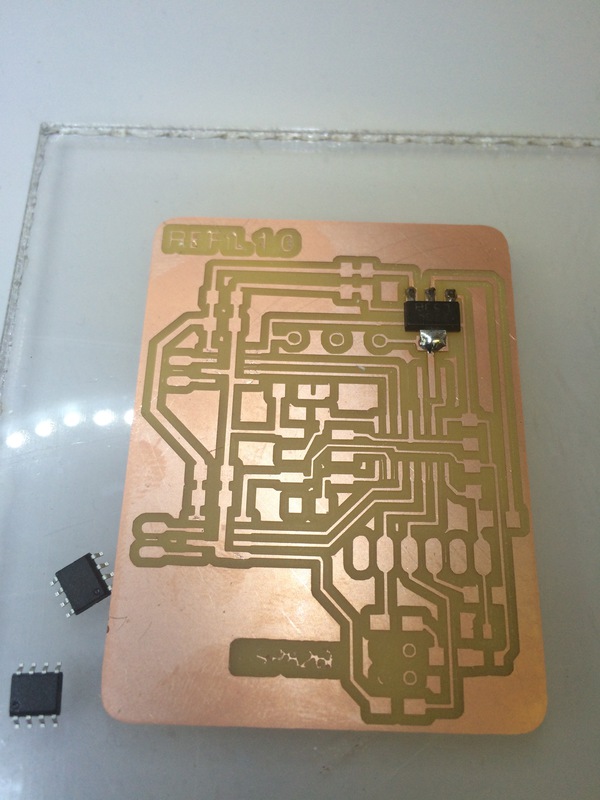
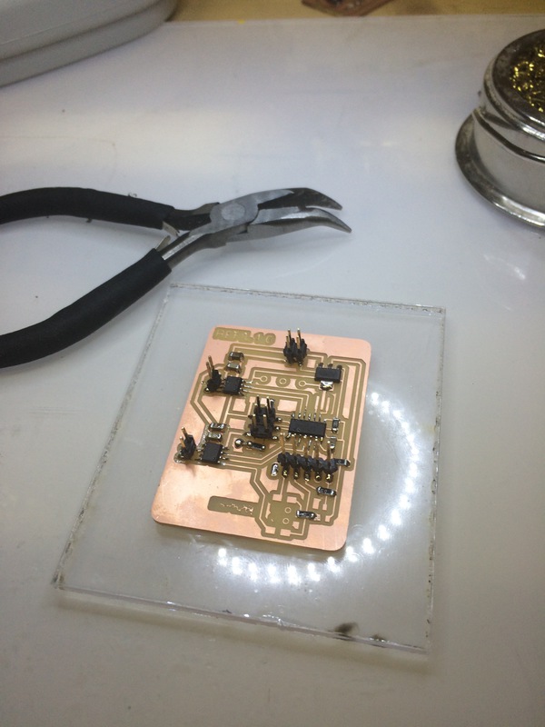
Milling and Stuffing took the better part of today. The Milling aborted strangely half way thru and I had to restart. Thankfully I wrote down the starting coordinates and just resent the job. It worked well. It took an age to stuff this board. We seem to have run out of Attiny44’s at my Fablab so I had to take a desoldered one. It did program so no loss there. Everything worked great except that the stepper ports ripped up and I had to super glue them down. The lesson learned is alway make pads long so that they stay.
what will it do?
The Refil Conductive Spinning Wheel allows the creation of conductive yarns by way of spinning and plying in a dynamically controlled manner.
Who has done what before?
Spinning dates back 16000 years, the goddess Athena is often depicted with a spinning whorl in her hand. Multiple advancements have been made. Most recently a kickstarter campaign made a version. Electric Eel Wheel - A Spinning Wheel for Fiber Lovers by Maurice Ribble — Kickstarter
what materials and components will be required?
- Frame
- Stepper motor
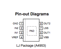
- Servo motor Datasheet A4953
- Control board EAGLE Regulator
- Wifi board
- Spool
- Power supply
where will they come from?
Fab Inventory
how much will it cost?
100$
what parts and systems will be made?
- Spool
- Spinning Whorl
- Bobbin Winder
- Frame
- Control Board
- Local website
what processes will be used?
- Laser cutting
- Milling
- Electronics Production
- Molding and Casting
- Interface and Applications
- Input Device
- Output Device
- 3D printing
what tasks need to be completed?
- Electronics Design and board milling. COMPLETED
- Stuffing board and testing. COMPLETED
- Bobbin and Whorl design COMPLETED
- Bobbin and Whorl milling and testing. COMPLETED
- Bobbin Winder design and mold milling COMPLETED
- Bobbin Winder casting and testing. COMPLETED
- Frame COMPLETED
- Web interface TO DO
- Reflection COMPLETED
what questions need to be answered?
- How do we wind the bobbin evenly?
- How can we keep proper tension?
- How can we tell if a thread or roving is broken?
- What are the extremes of whorl in terms of condutivity?
- How much yarn can be produced?
what is the schedule?
- Day 1 Electronics Design and board milling. COMPLETED
- Day 2 Stuffing board and testing. COMPLETED
- Day 3 Bobbin and Whorl design COMPLETED
- Day 4 Bobbin and Whorl milling and testing. TO DO
- Day 5 Bobbin Winder design and mold milling TO DO
- Day 6 Bobbin Winder casting and testing. TO DO
- Day 7 Reflection TO DO
- Day 8 Frame TO DO
- Day 9 Web interface TO DO
how will it be evaluated?
- Quality of spun yarn.
- Quality of spun thread.
- Quality of plied yarn.
- Conductivity.
- Device website.
- Quality of processes employed.