Fab[Valentin]ISP in-circuit programmer

Customizing Files
I choose to make a Valentin FabISP in-circuit programmer. It's peculiarity is to have a milled USB connection and “broke-able” jumper.Starting from the downloaded .png scheme, I customize the file inserting the ProdActive Landscapes logo. So I took-off the round hole from the cutout.png file and insert the logo in the ISP.png file, in the same position, by using Gimp.

Milling settings
In order to test the machine (Roland Modela MDX 20) I choose to send first a cutout path at 0 deep. So by using fab modules, 9,5 as x,y 0 position and z 0 position manually set, I send a first ride with 1/64 milling-bit discovering that the plan is not plan at all. So with Ferdinand,our tutor and saver, in order to save the milling-bit we choose to send the ISP path in different times starting from 0 and go increasing instead the usual 0,10mm.

During the first ride the machine stopped after at screen-saver starting, in doubt if the two things were related we took of the screen-saver setting and restart. In order to save time we chose to set 4 offset paths instead to cut off all the copper with a -1 setting.
After 2 more ride with 0,06 and 0,15 setting we finish to mil the board and we were able to pass to the cutout file setting 3 overlapped path to 0,35 mm.

Soldering
Based on the plan file I collect all the components necessary and start to solder them starting from internal and smaller. 2 hours later, after check, and change, diodes direction we made the first programming test.

Programming checking and try again
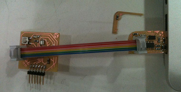
Connected to the AVRISP mkII programmer the board was looking working. Programmer's led was green and we start to programming procedure has explained. Get to the Make program we received back and Error message. Than we pass to check all solderer back and re-try. At the second time the programmer' led was blinking yellow. It took one day of research to find that a copper connection was broken in a corner. So we made a bypass with a cable and check if other copper collection were making short, than we retry to connect it to the programmer and the led comes green.


So I pass to the programming procedure. That didn't give any error message back! It FabISP should be working now. But after disconnect the programmer and re-connecting it back the FabISP wasn't recognize by any OS.
Checking a second time finally we found a that instead of a 499 Ohm resistor there was a 499E resistor. Once changes that component the FabISP was readable from the computer and ready to be “broke”.
I 'll test it in the Electronics design week