Week 14 - Networking and Communications

This week we are looking at how to get two seperate boards to talk to eachother wired or wirelessly. This will allow us to tie together what we have done so far in electronics and help us think more about what electronics we wish to include in our final projects.

Assignment:

design and build a wired and/or wireless network connecting at least two processors


29th April 2015 - Bluetooth and GPS!

For the benefot of my final project, I thought it would be appropriate to try and set up communication using two bluetooth modules. Then to top it off, use the readings from a GPS module as an input on one board and an RGB as an output on the other board. Pretty abitious but worth trying.

My next steps are to look up some tutorials and try to understanf how to set up such a communication.


30th April 2015 - This is gonna be tricky...

Today I started to look up some tutorials and usage examples of the modules I wish to include. I looked at this tutorial which described how to set up a connection between two HC-05 bluetooth modules. Sadly it isn't quite as simple as one would think and the tutorial assumes you want one module to be controlled by your computer. Therefore this didn't apply to what I wanted to do so much. But it was helpful in explaining how to set up the module as a master module (the default for these modules is slave).

I also found a handy project which makes use of a GPS module that they had at the lab. I was to make a GPS dog collar. The useful bits for me were the schematic and the code used. From this I can design my own scematic to suit my needs and then code it.

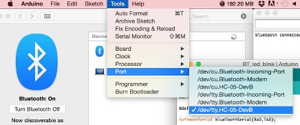
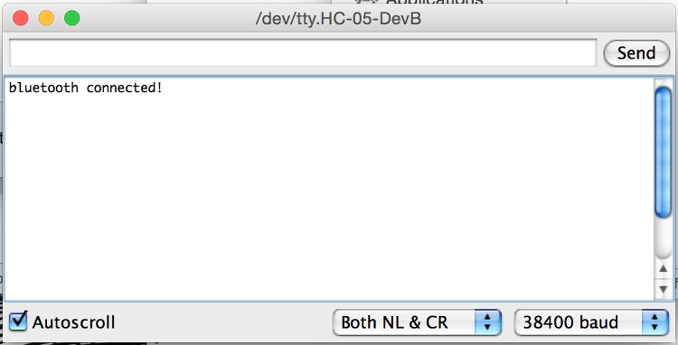
One last page I used was that of ex fabacademy student Keiichi Onishi. They attempted the same thing as I wish to attempt ie getting two bluetooth modules to communucate with each other. However, like I have found, it is very tricky to do so. Instead they connected one module to their computer and controlled the board from the terminal. There was also a very handy tutorial included, which would allow me to do this. It has a great example code which I will make use of.

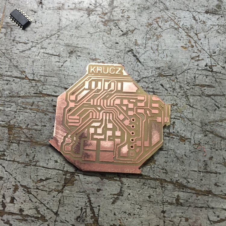
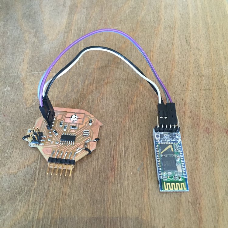
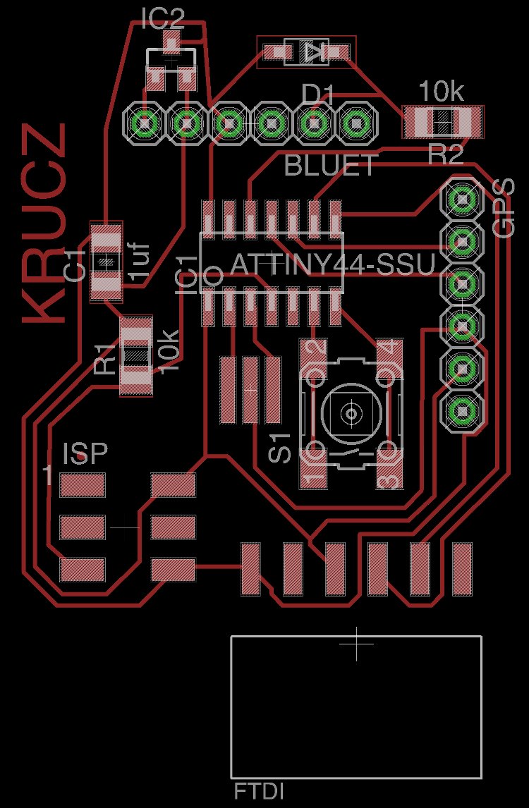
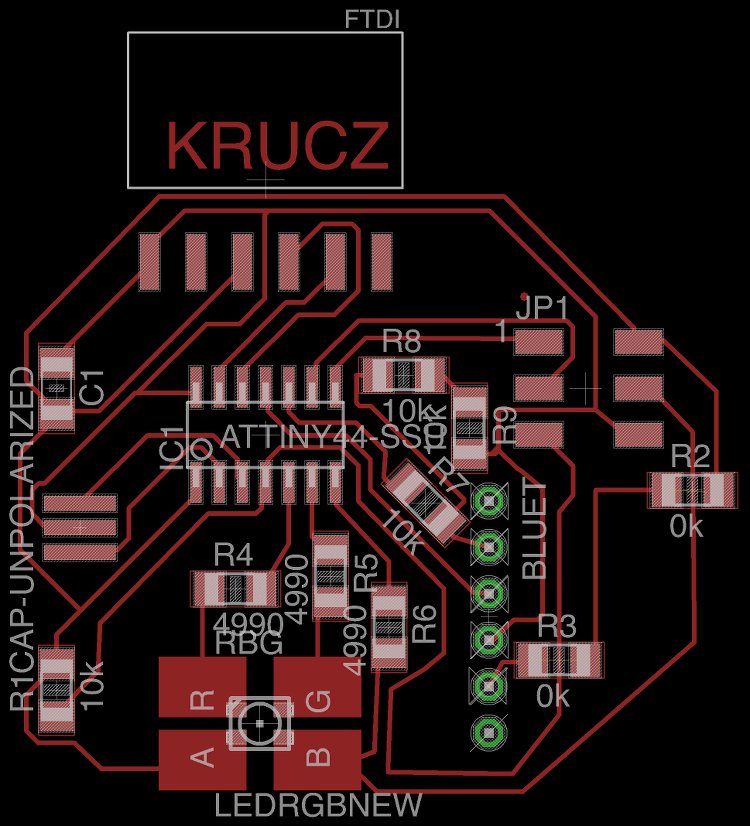
I went on to design two circuit boards. One with a GPS and Bluetooth module and the other with an RGB and Bluetooth module:


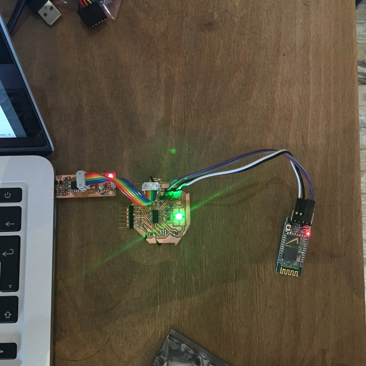
To ensure I finish the assignment this week, I will make the second board and get it to communicate with my computer. Then, if there is time, I will mill the second board and work on how to set up the communication between them.


3rd May 2015 - Milling my board

I milled out my board and made a stupid error. I changed the traces of my design and forgot to update the cut file. Hence some of the traces were cut away and I had to solder on two wires as jumpers.


To ensure that the board was working I uploaded the blink sketch from the arduino environment. This worked so I set on trying to connect the circuit to my computer. I took the code given in the tutorial used my the other fab academy student I mentioned and adjusted it accordingly:


#include  <SoftwareSerial.h>  //Software Serial Port
#define RxD 3
#define TxD 2

#define DEBUG_ENABLED  1
 
SoftwareSerial blueToothSerial(RxD,TxD);

int led1 = 7;
int led2 = 6;
int led3 = 8;
 
void setup() 
{ 
  pinMode(RxD, INPUT);
  pinMode(TxD, OUTPUT);
  setupBlueToothConnection();
  
  pinMode(led1,OUTPUT);
  pinMode(led2,OUTPUT);
  pinMode(led3,OUTPUT);
  digitalWrite(led1,LOW);
  digitalWrite(led2,HIGH);
  digitalWrite(led3,HIGH);
  
 
} 
 void setupBlueToothConnection()
{
  blueToothSerial.begin(9600); //Set BluetoothBee BaudRate to default baud rate 38400
  blueToothSerial.print("\r\n+STWMOD=0\r\n"); //set the bluetooth work in slave mode
  blueToothSerial.print("\r\n+STNA=HC-05\r\n"); //set the bluetooth name as "HC-05"
  blueToothSerial.print("\r\n+STOAUT=1\r\n"); // Permit Paired device to connect me
  blueToothSerial.print("\r\n+STAUTO=0\r\n"); // Auto-connection should be forbidden here
  
  delay(2000); // This delay is required.
  //blueToothSerial.print("\r\n+INQ=1\r\n"); //make the slave bluetooth inquirable 
  blueToothSerial.print("bluetooth connected!\n");
  
  delay(2000); // This delay is required.
  blueToothSerial.flush();
}
void loop() 
{ 
  char recvChar;
  while(1){
    //check if there's any data sent from the remote bluetooth shield
    if(blueToothSerial.available()){
      recvChar = blueToothSerial.read();
      
        if(recvChar == '1'){
          digitalWrite(led1,LOW); 
         
         delay (1000);
         
         
    }
        else{
          digitalWrite(led1,HIGH); 
        }
    }
  }
} 


I uploaded this and connected the bluetooth module to my computer as you would with any other device:


I then opened the serial communication window in the arduino environment. Ensure it is set to the correct port.


Now this is done you can open the serial communication window in arduino and talk to the board. In the code it should send a message to the window saying "bluetooth connected!". Unfortunately for me this wasn't the case. The message didn't appear and if I typed in the command to turn the LED on, nothing would happen.

The most probable cause was that I had assigned the wrong RX and TX ins in my code. I went back to my design file and double checked. I turns out they were the wrong way around. It is important to remember that the TX of the controller should be connected to the RX of the bluetooth module (and vice versa).

I corrected this, uploaded the code and voila! The serial window said "bluetooth connected!".


After many attepmts to send commands, I still wasn't able to control the LED. Time to sleep on it and come back to it tomorrow!


30th April 2015 - A mirage of a debug!

After another few hours of "debugging" I realised that I needed debugging.... It turns out that I was controlling the LED! But it would only turn on for a fraction of a second, hence making it almost impossible to notice!

To fix this (temporarily) I added a delay so that the LED will stay on for longer before turning off. This can be seen in the video below.

The green LED signifies the board has turned on and has set up the connection with the bluetooth module.

The red led shows that the bluetooth module is powered.

The blue LED shows when the board is being programmed.

In the video below you can see me upload two arduino files to the board. The first one makes the green LED blink once when you type "1". Then I uploaded another file which fades the Blue and Green LED depending on how many "1" characters you send to the module. One thing I am struggling to do is to keep the Green LED on. The only way I have been able to keep it on is by adding a delay. You can see me add it during the video.


That is the assignment completed for this week! Here is my design files and code. I will try to work out how to use the GPS module and pair two bluetooth modules if I can.