Week 13 |
Networking and Communications - April, 29th 2015
Designing The Boards |
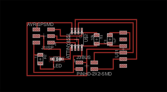
The assignment this week was to design and build a wired network and / or without connecting wire at least two processors. My choice was the safest possible: something that could actually work and make me understand its operation. The best way to achieve this for me, was to make asynchronous serial, meaning in practice a brigde with two nodes. Followed the same process for all boards: designed them in Eagle, made them ready for machining in Photoshop and milled at Roland SRM-20. At Eagle
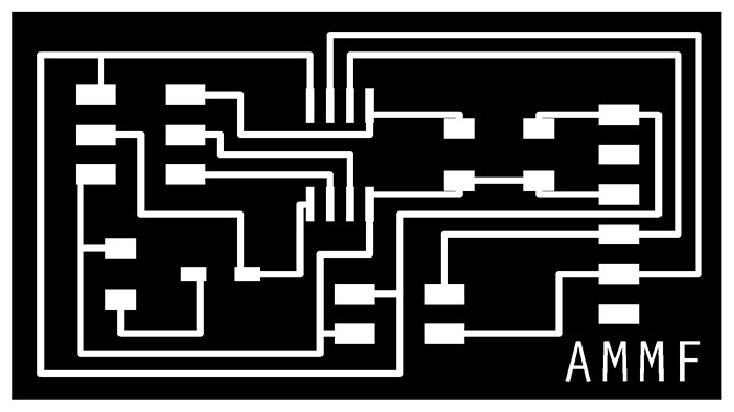
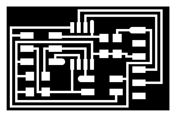
At Photoshop
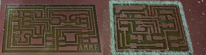
At Roland SRM-20
|
Fixing Errors |
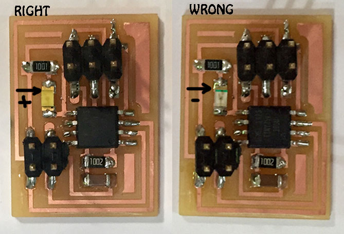
Next step was welding my boards, so I got all the components, they were exactly the same for the three boards, excepting for the bridge which also has a FTDI connector, which feeds the plates. When I had finished welding them, and I went into programming, I realized that the LEDs were not working, and looking more closely, I realized that I had put them in the wrong position: which was I connected cathode (-) to GND on both nodes. A Little Detail
|
Programming |
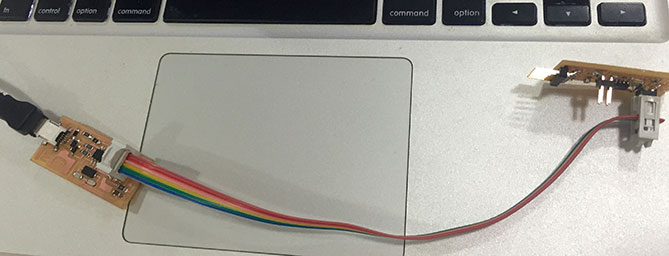
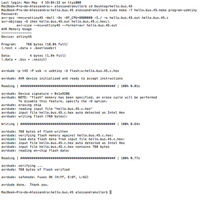
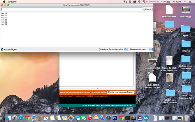
To program the boards I first used my ISP board following the tutorial. It was ready to make the second step of the process. Then immediately programmed the nodes 1 and 2 through the bridge. To test it I used Arduino and the leds were blinking after my command! ISP And Bridge
At Terminal
At Arduino
|