Dark blue spring sky
sitting high above my head
yet i can barely remember how
yellow the slide was where
I'd watch my parents sit and smoke
as my youth would flash down
into the dirt
Project outline
Franz is a mechanical wall- mounted toy, it's wondrous and a bit weird. The kind of toy that grownups keep to themselves. You really want to touch it but you're never allowed because it's too precious to really play with.
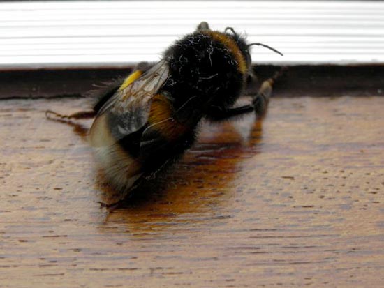
Franz is a bumblebee. He's a bit overweight and just sits in his little capsule, looking at the world. Although it looks impressive in size, you can't help but wonder if it's already dead or not, you just hear it buzzing a little bit sometimes. You can't touch him but you can blow at him to find out if he still has some life in him.
Materials and components
The body
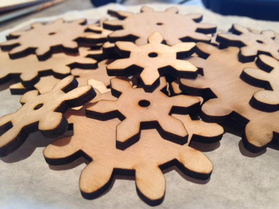
Franz's body and wings are 3D printed. The hinges are also 3D printed and screwed into the body. The bell glass encasing is made of an acrylic sheet made with free dome blowing technique. The wooden frame is made with the shopbot (3D, onesided). His eyes are small incandescent light bulbs. Gears are cut with the lasercutter.
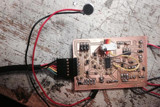
Electronics and mechanics
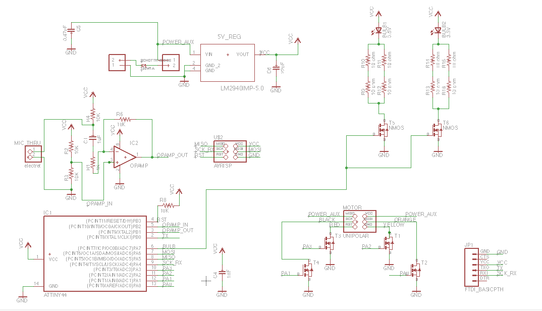
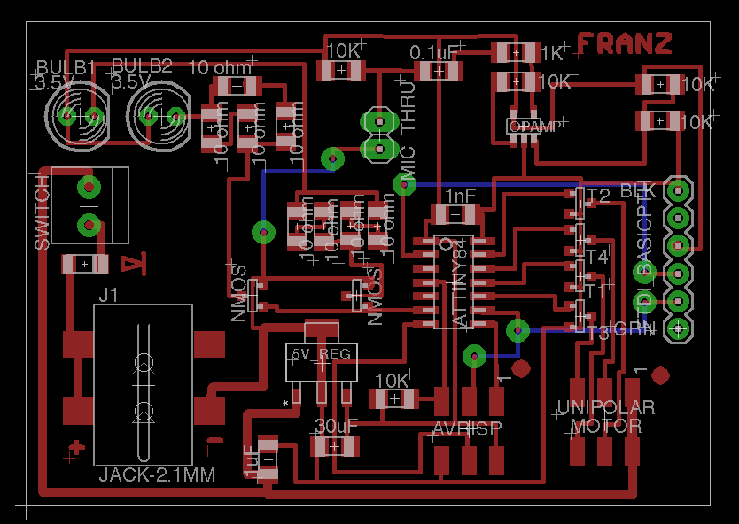
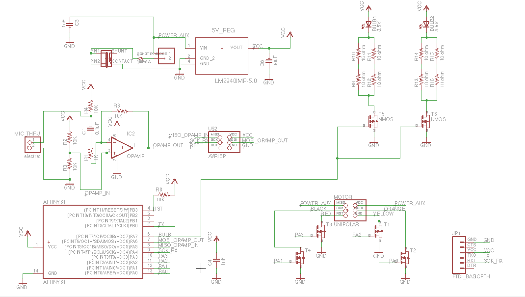
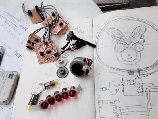
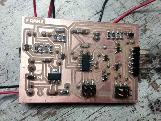
The electronic circuit is a milled board consisting of an attiny44, interfacing an microphone/opamp combination as input, and a unipolar stepper motor as output. The microphone is encapsulated inside the wooden frame, outside the bell glass. The motor drives acrylic gears and two cams (lasercutter) to move the wings. The axes are cut to size and given a thread. Fastening of the gears is done by creating a flat box made of transparent acrylic or wood with cutouts to hold the axes in place on both ends (lasercutter). Power supply is a repurposed laptop adapter.
Sources of inspiration, building on others
A great source of inspiration are have been automata from back in the day, but also more contemporary examples. Moving things somehow are still a source of wonder. The book Making Things Move by Dustyn Roberts has been really helpful in understanding some of the basics. This BBC documentary is a nice account of the history of automata:
And Kazuaki Harada's work really embodies the simple joy of making moving apparatuses that are a bit non-sensical but very joyful at the same time. His automata - even when they're complex systems - have a very simple aesthetic and a sense of transparency that shows the beauty of the mechanics inside.
Finally there's loads of other examples in the domain of kinetic arts that have been hugely inspiring. Some of them are below. I suppose the challenge in these works is to achieve the right aesthetic in materials, forms and movements. The following examples are quite advanced, but having studied a range of examples for a first project, it seems that an interesting aesthetic can often also be achieved without necessarily creating very complex systems.
Jennifer Townley's "Bussola"
"Denizen" by Potts Sculpture
Then definitely worth mentioning are Ralph Steiner's Mechanical Principles videos from the 1930s. They show a wide range of beautiful ways to transfer movement.
Where do the materials come from & costs
Cost estimation is largely based on the Fablab inventory list and/or on prices at local/alternative suppliers. I've made a very rough prototype to figure out some of the sizing and dimensions to make an informed estimation for the cost. Some of the estimations are based on previous assignments. Total as listed below amounts to a total of $ 110.32 (or $ 149.54 when all materials that I already had or found are accounted for).
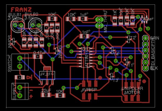
My circuit board design requires an electret microphone as input, and a unipolar stepper motor and 2 incandescent light bulbs as output. I decided to put it on one board because:
The motor alone already needs a lot of pins, so attiny44 is preferred over 45
But the TinyWire lib is not supported, so communication with a master/slave setup (I've done I2C) will be difficult. One board will be easier in that sense
There's not that much on this board so it should be ok
Electronics issues to be resolved
Improve current flow
During the output devices week I found that the unipolar stepper draws a lot of current that the board I'd made could hardly supply (battery died quickly). So I needed to improve that by replacing the regulator with one that could give more amps, and do the same for diodes and power supply. Because there's no datasheet for the stepper, we measured the resistance on the coils to find out the current it requires. Each coil takes 250mA, so at least 500mA should be accounted for in replacing the parts mentioned above.
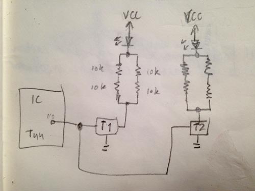
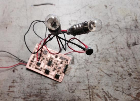
Incandescent light bulbs
Then I had to find a way to put the beautiful and challenging incandescent bulbs in there. They're 3.5V and 200mA, which is also a lot. I could do with less and get a faint bulb, but let's optimize. Because the I/O pins of the attiny can only supply 40mA, I had to add an N-mosfet on an I/O pin for each bulb and connect them directly to VCC. In order to end up with a lot of Watts on the bulbs, I had to add two parallel pairs of 10K resistors in series for each bulb.
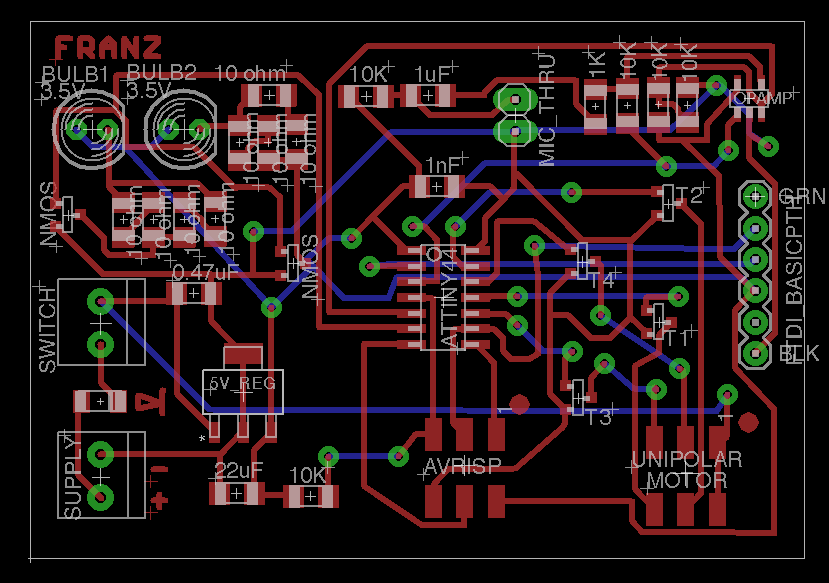
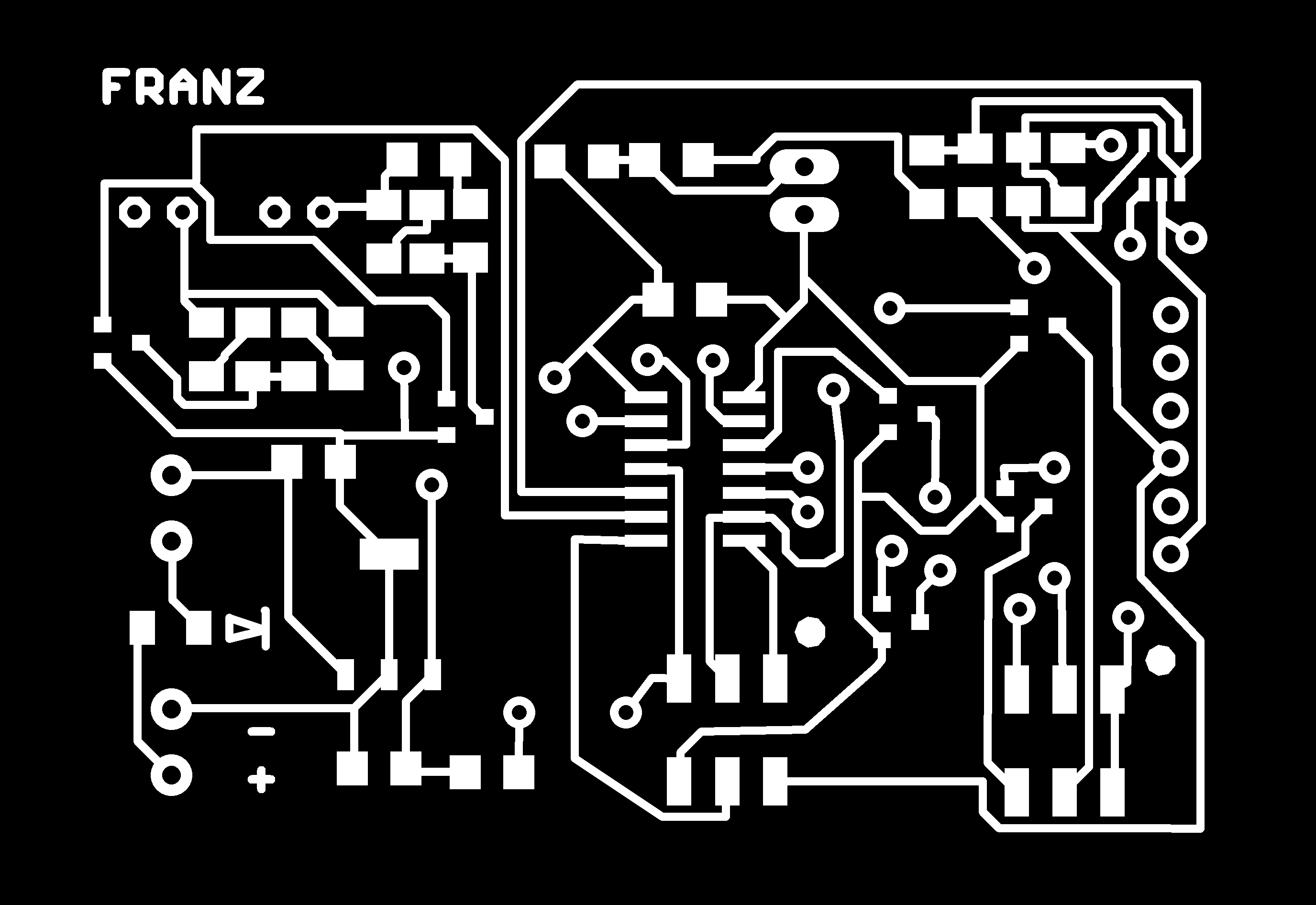
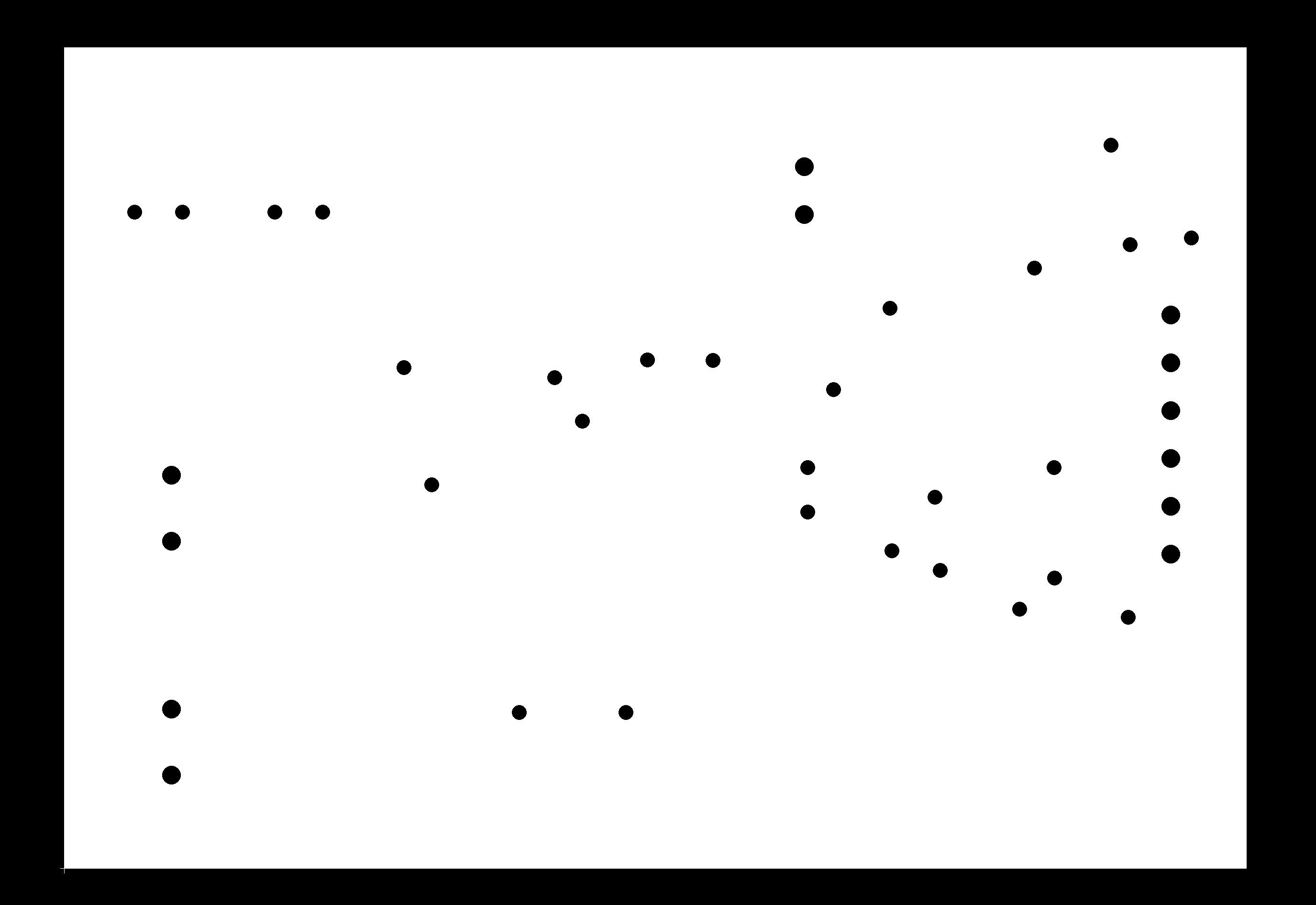
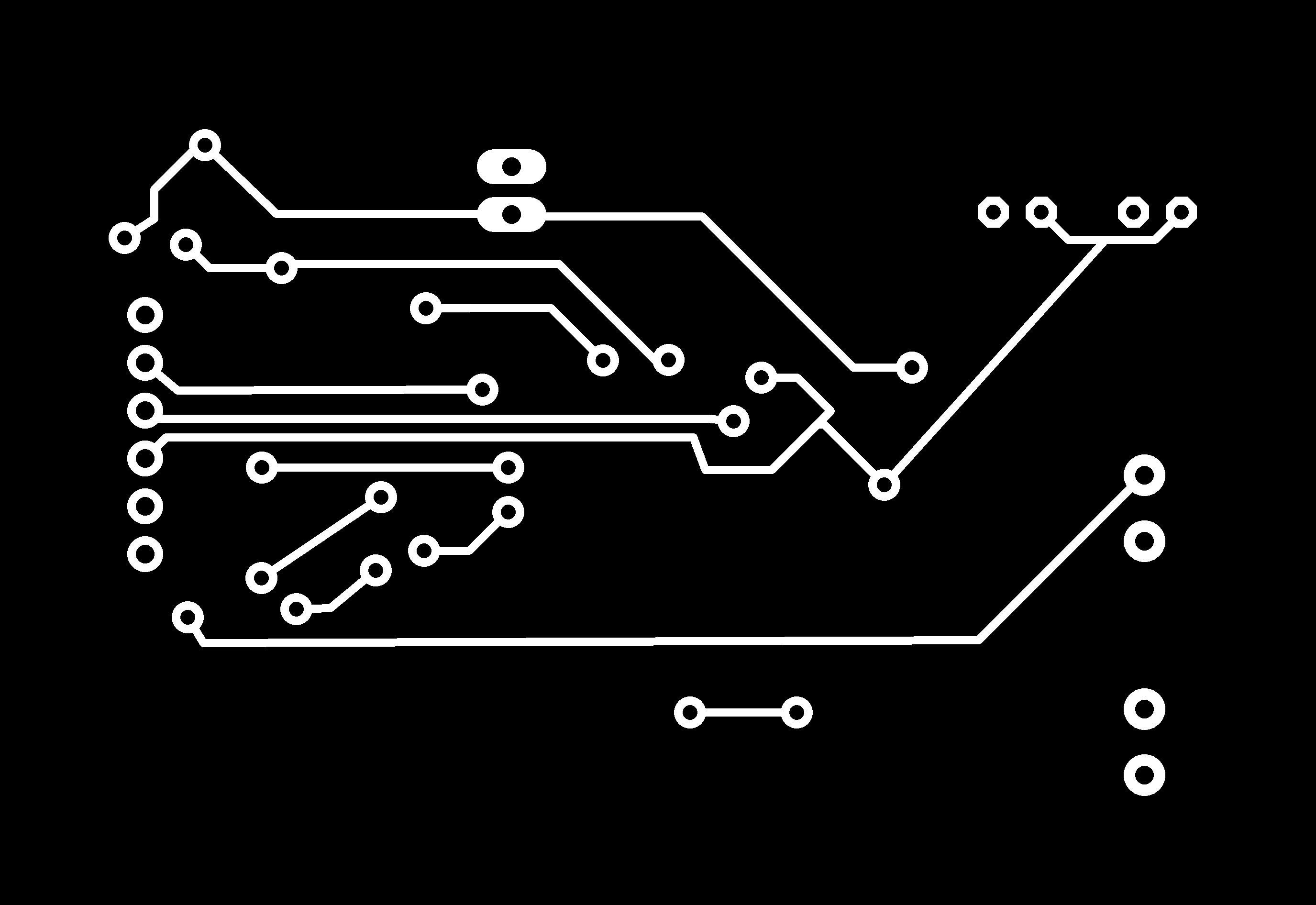
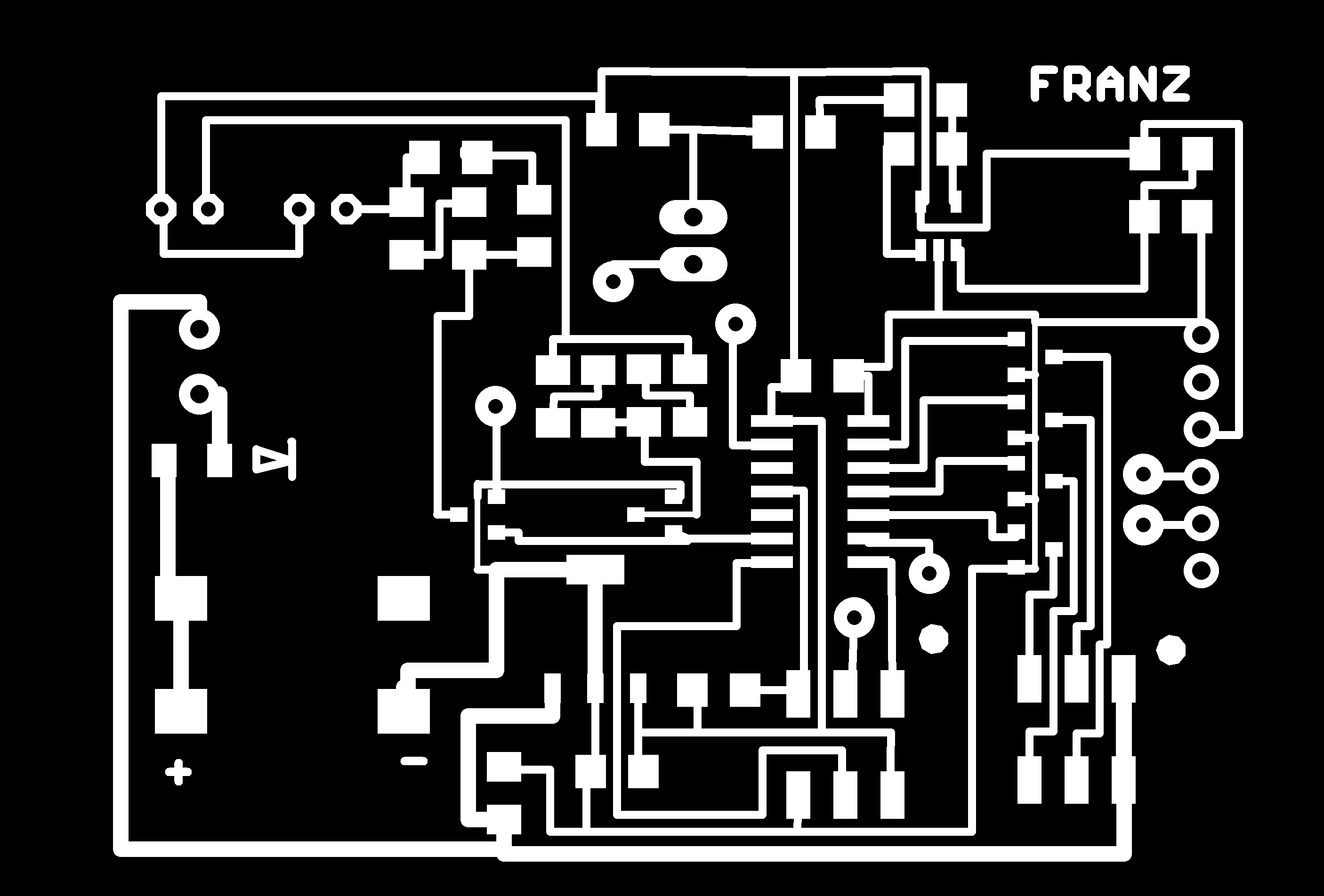
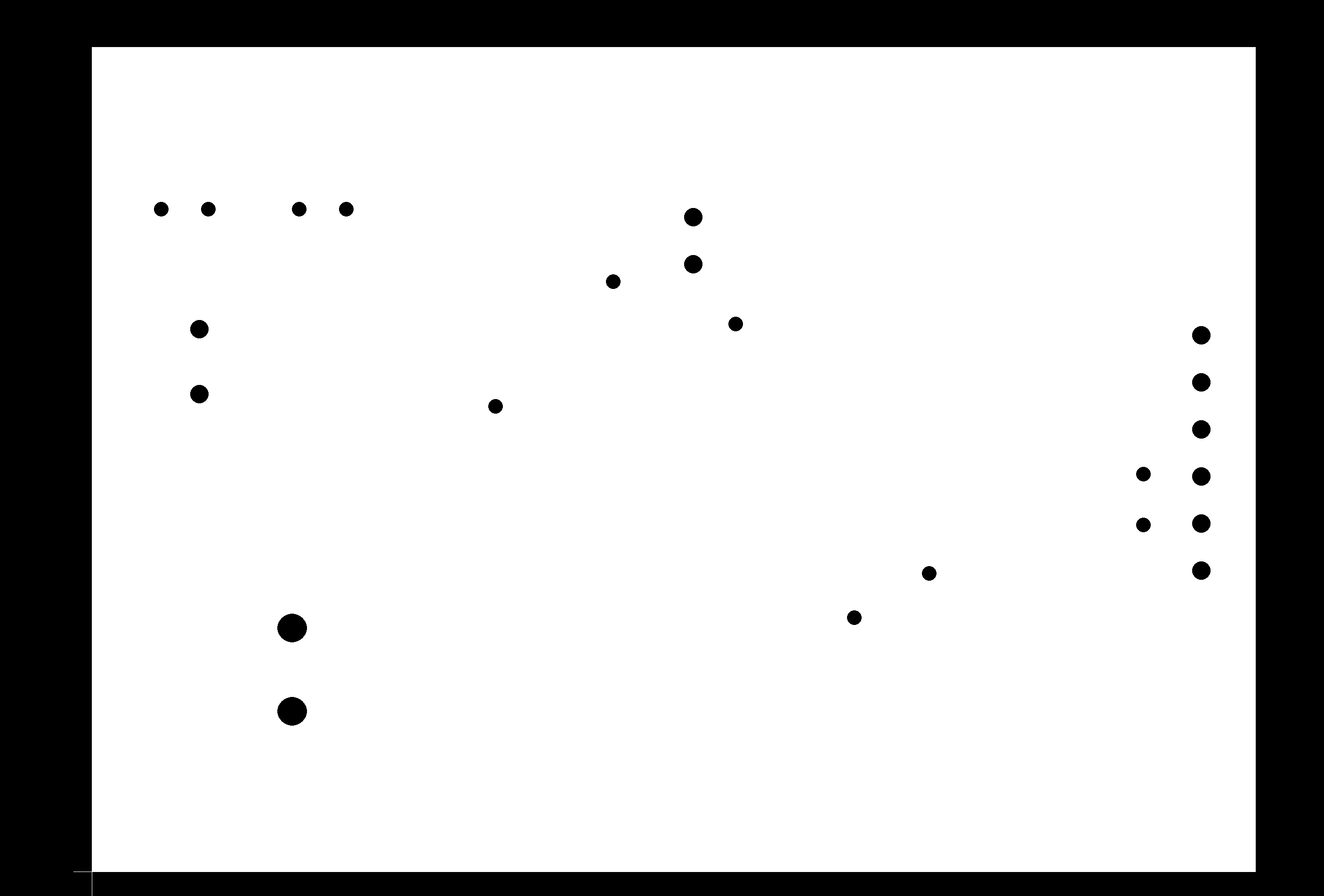
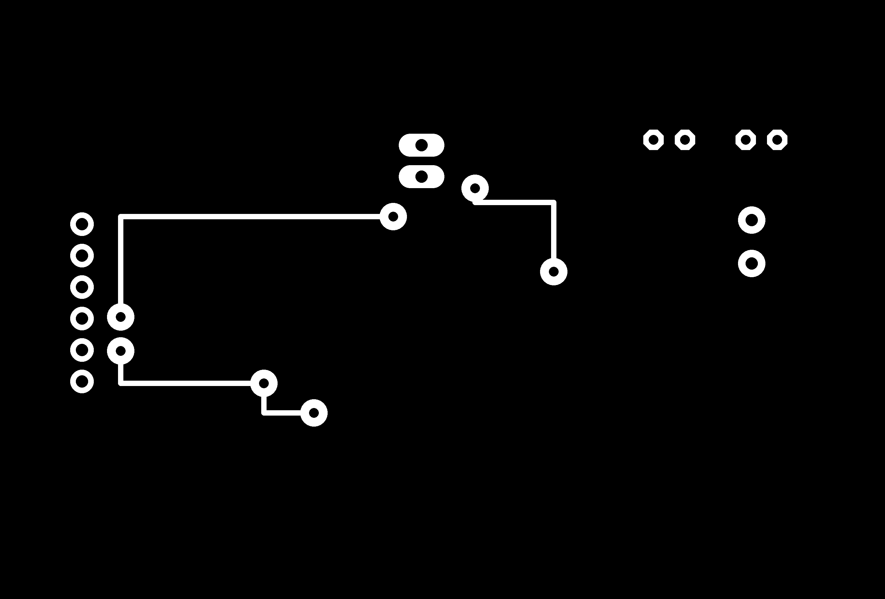
I went on to make the schematic and design the board layout. One sided was going to be very messy so I opted for double sided. Workflow:
Use top and bottom with autorouter
symmetrical board shape = easiest (eg rectangle or circle
Fix bad positioning of vias and thickness if necessary
3) sand off the square edge of the corner that will be in x,y 0,0 when you flip the board (or make a dogtooth in your design if you're smarter than me
stick it as tightly in the corner as possible
5) -1/32 inch on x & y to compensate for diameter of milling bit4) mill BOTTOM
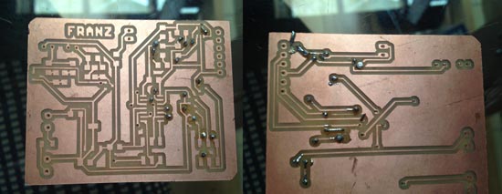
The first attempt failed because the autorouter had put vias underneath the IC and very close to legs of other components, which made it near impossible to surface mount solder them.
Also the via's traces were way too small. Because there's always some misaligment when flipping the board to mill the back traces, the mill also went through them. Tearing them off during stuffing was unavoidable. So I made a new board with better spacing and thicker via traces.
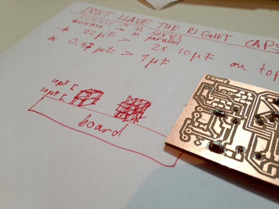
Soldering the vias of the second board was a lot better and I could do it without problems. As I was stuffing the board I noticed that I had to capacitors on the board that we didn't have in the inventory: 22uF and 0,47uF. The 22uF on the input of the regulator could be solved by stacking two 10uF caps on top of one another in series. And I replaced the 0,47uF with a 1uF cap for the output of the 5V regulator. The original numbers were based on suggestions in the datasheet, but they're safe for up to 1A and I'm not nearly using that much (more aroung 500mA). So the informed guess is that this will be safe.
Electronics debugging
I stuffed the board to find out that the 2-pin terminals couldn*t be soldered onto the traces because there were some traces on the bottom and some on the top. You have to solder these through-hole terminals on the side where the traces are, and it can be only on one side. I solved it for now by just soldering the supply wires to the board and closing the switch with a jumper.
So I closed the switch port with a jumper for now (will be working with the desktop power supply for debugging so can turn it on/off easily). And I just soldered a + and a - wire to the board rather than using a terminal so I can supply the circuit. I can solder the laptop adaptor to the board at a later stage, or create another board for the supply and connect it to the main board. the biggest challenge I encountered was that some components acted as a via as well, so I had to solder some throughhole components rather uncomfortably on two sides to connect top and bottom as a via.
Programming
When the electronics were all ready to go I started working on the electronics:
Workflow
Re-burn 8mHz bootloader to be sure
found out I connected the FTDI traces weirdly: plug cable in upside down!
Find RX/TX pins on pin, (swap for the code). Schematic on chip: RX = 9/PA4 (arduino > pin 4), TX = 2/PB0 (arduino > pin 10). So in the code they will be swapped: RX = 10, TX = 4).
Do calibration of the clock with Zaerc's script. Add OSCCAL= 0x91; // is calibrated clock value using tinyOscalTempt44
delay(1); to void setup.
check serial communication with basic serial code. Looks good.
get blink and fading sketch to turn bulbs on. The mosfet is controlled with IC pins, but need external supply to get the bulbs to go on. Didn't work. Found mistake in values of resistors before bulb (10K instead of 10 ohm). Replaced them and adjusted schematic for later reference
Get mic to send values to board.
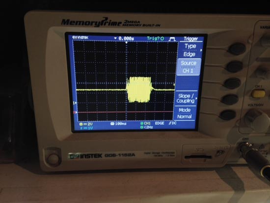
There were some issues....When I look at oscilloscope there's a very clear signal when blowing into mic. It's just not coming through to computer. Realized I*d put the opamp pins in the PB register (no ADC...!) (Analog to Digital converter) that you need to translate the values. OK great, clear problem. Made a second connector with ribbon for the ISP header, and to repurpose the MISO and MOSI pins. Solder wires to opamp. Alternate between headers for programming and execution.
I fixed this problem by making another 6-pin connector for the ISP header and put a wire into the MOSI and MISO slots of the header. I soldered the ends of the brown and yellow wire to the opamp_in and opamp_out pins on the attiny on the board. Changed the pins in the code and voila, absolutely beautiful values from 0-512.
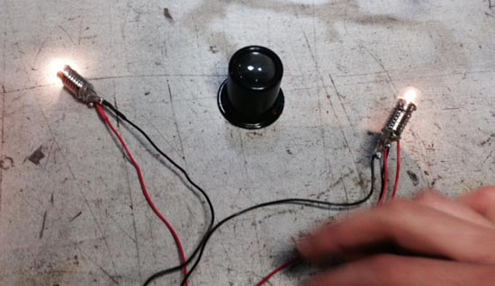
Also made a mistake in the capacitors on Opamp circuit: changed 1uF cap to 0.1uF cap (see Neil's layout) and changed it in schematic for later reference. But.....the mic and the bulbs are now working together like a team: disco!l
Turn motor on and off: no problems there
First I combined the MIC input and the bulbs. I was a bit worried because I noticed that I was running out of sketch space realllllly quickly. But we'll see how it goes when I start working with the motor. I could change the 44 for a 84 ATTiny which has more flash space. I did that when I burned the chip and mosfets when working with the supplies. Did the whole workflow again for the ATTiny84. Turning the motor on and off was relatively simple with the Arduino Stepper library.
Get external supply to power the board
Everything works fine with FTDI or ISP as supply, but it doesn't work with the big DC power supply. We found out that the regulator is unstable, so nothing is behaving, lights are going on and off. On the oscilloscope you can see the signals flailing. We're going to add another 10uF capacitor to the stack at the output of the regulator to stabilize this. Success!
Combine all functions, do finetuning for aesthetics etc
Thennnnnn a matter of putting it all together! What I wanted was to keep the flickering bulbs while you blow into the microphone, and I'd want the motor to keep running a little while after you stop blowing and then for it to slowly come to a halt. Like so!
Problems with stepper library and power consumption of stepper in static mode
I found that the motor is consuming a lot of power when it's not turning: even up to 800mA. This is so much that eventually any motor will burn. The way to avoid this is to write a timeout function in the code where all the motor pins are turned low when it's not turning.
But them there also seemed to be an inefficiency in the stepper library. For some reason the stepper will ask for up to 900mA on its own when using the Arduino stepper library, where one would expect 500mA max (250 per coil). I wrote similar code to control the stepper without a library and then it doesn*t consume more than 500mA on its own. Together with the light bulbs and mic it will ask up to 700-800mA but that's still fine for a circuit that is designed to take up to 1mA. However, with the stepper library the circuit is asking up to 1.3mA which burns the regulator. I haven*t gone into great depths to understand what it is in the library that causes this, but avoiding the library is a way to do it.
Oh and the command avrdude -c usbtiny -p t84 is my bestest friend now. Use it if you want to check whether the computer can still see your board. It happened many times that I couldn't upload it, but when you can see it again in terminal with this command it is ready to receive instructions.
Material choices
I had a few non-negotiables in terms of materials:
Fastenings: I wanted to use brass capped nuts with copperplated shafts where possible (I could use this for the longers ones, really short ones are dangerous to cut and thread by hands so for those I used screws
Filament for the bug: the nature of the design required me to do an ABS print at work that builds soluble support structures that you can wash away. Only off-white is available for rapid prototyping and that was fine by me. I also wanted ABS because it allows for a nice polish.
Wood for either gears and/or encasing
no LEDs! I want incandescent light bulbs because they're sooooo pretty
As for the gears and encaseing. I really didn't have so many wishes because I needed to work out what works well in terms of mechanics. Turned out that acrylic was by far the easiest to work with for the gears. And I found a wonderful 6mm thick tan brown color acrylic in the leftover box. I had to be really careful because there were no second chances with this small amount of material. I chose some wood with the same pinkish undertones for the encasing. and transparent acrylic for the top layer. I'm quite happy with this combination and dropped the idea of an additional frame and half glass dome because I think that would be too much.
Mechanical design and casing
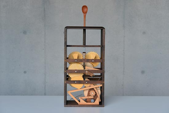
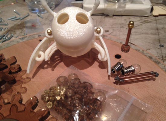
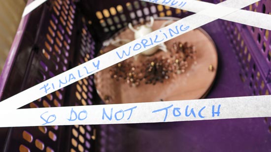
Designing mechanics was really the most daunting to me. I had measured all my bits and bobs already so I could take sizing into account in the designs as much as possible. I'd made many naive mistakes by making just a simple prototype (see picture on the top) which helped. What I needed to do was:
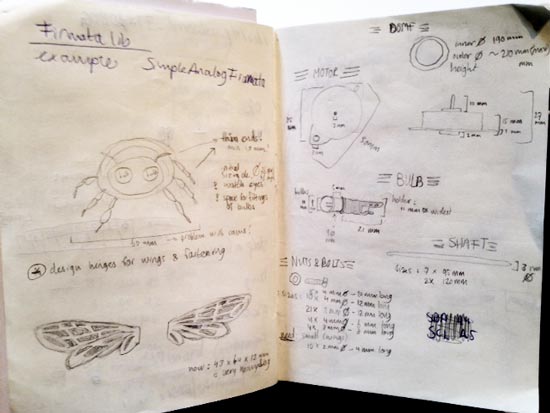
design the body of the bug with enough space for lightbulb eyes & wires. Check wall thickness for printing. Design fastenings to back of wall monunt
design 3D mold for the wings to do a lay-up composite. Make sure body and wings fit into dome
design fastening and hinges to assemble body & wings. Make sure it can move smoothly, make sure it fits in the dome
design gears to drive the wings up and down. Be aware of appropriate sizing and distance (see notes on gears in Making Things Move
design stages to get the gears at the right height (make sure shaft can rotate within)
design box to hold shafts, motor and gears into place, fit within dome. Account for wiring
design frame for dome and back of the dome. Allow for electronics to fit between.
And finally do 2D designed cutouts to lasercut the textiles for the composites
I found myself switching constantly between these tasks because everything is interconnected in that sense. I would just start with something. And constantly try to reference it with the other things to see if it would all fit and work.
Gears design
The most important things to make gears mesh is:
the diametral pitch should be thesame for all meshing gears
1/2 the pitch diameter of the first gears + 1/2 the pitch diameter of the second gear = the correct distance (p38 of Making Things Move)
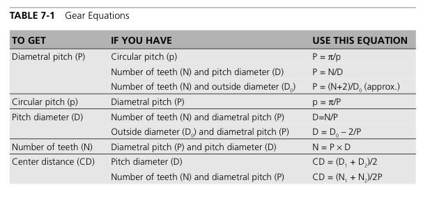
Inkscape has a gear generator under > Extensions > Render > Gear. That allows you to specify these parameters : number of teeth (N), circular pitch or tooth size (p), pressure angle and hole diameter for shaft. With N and p you can calculate diametral pitch (P) and D (pitch diameter) to work out spacing and sizing with the conversion table below)
The constant for my gears is that the circular pitch (p) = 12.0. I can change the sizes by varying number of teet (N) in the generator.
I ran a materials test with my shafts to see how big the holes should be to have a very tight fit of gears on the shafts. And also how big the holes should be to allow them to move. And then I tested out the distance formula mentioned above to locate where holes for the shafts should be. The calculations seemed to work, but the gears get stuck occasionally.
Sizes: 3mm shafts need a 2.85mm hole to rotate smoothly, the motor shaft needs a 1.80mm hole in the gear to be snapfit (but add glue anyway). This test was done with 3mm acrylic sheets cut at power 100, speed 0.7 so can vary at a later stage. The gears were a bit tight the first time around. So I gave the outside paths of the gears an offset of -0.3mm so there would be some more space between them. Bingo!
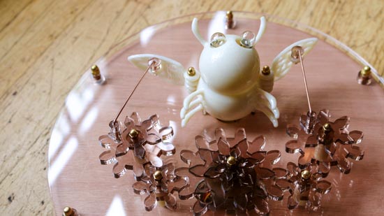
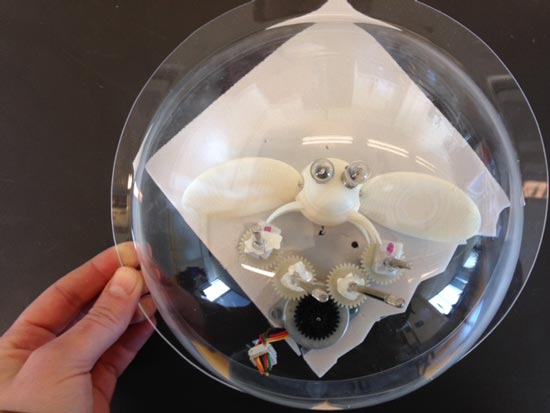
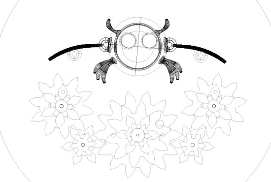
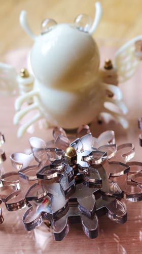
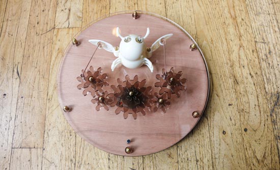
Then I worked on their aesthetics a bit more: I layered the gears with decorative gears so that they look like flowers. And I started putting things together, adding solutions for the cams and making cutouts for wiring and fastening of the bug and motor.
I tested it and was told that it's really vital to have everything superfastened. So I will have to make a thicker bottom plate to attach everything to reduce wobbling shafts. I need to have rounder teeth and as little clearance tolerance as possible for the active gears. Decorate the hell out of the top ones, not the active ones.
Then I found out that transporting the gears from the generator in inkscape to illustrator (for the laser) had changed the sizings with a factor of 1,24425802247923? ? so I had to adjust for that... The gears still didn't work so I manually changed them to make them rounder. I made the teeth 0,1mm wider and a bit shorter because that's where the gears kept blocking.
This also didn't work. By this time I'd gone through a lot of iterations of gears: rounder, thicker, shorter teeth, thicker material, with offsets, with different shafts, in wood, in acrylic, you name it. The gears still kept blocking and I'd quadruple checked distances between the shafts, but they were correct. I found that the laser hadn't cut my 6mm acrylic gears straight. This apparently is something that the laser always does but it shows more with thicker materials than with thinner ones. With bare eyes you could see that the bottom was wider than the top in some places. This would of course cause a lot of friction and pushing between the gears. This can be improved by focusing the layer on the middle of the material rather than on the top of the material, but I didn't have enough acrylic left to do this. While I was thinking of ways to fix this (shopbot them? give a generous offset? something?) I decided to go back to my original idea to keep the motor on top of the surface layer, and put the gears on a little cylinder to give them the appropriate height compared to the motor gear. This makes the entire thing REALLY wobbly, but it turned out that that's exactly the kind of play the uneven gears needed to work. And I suppose it takes away the factor of surface tension to a great extent. So I decided to go for that and keep the gears because I was also running out of material.
Design of the bug
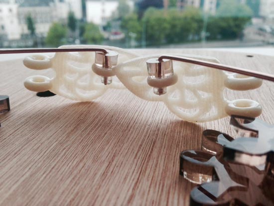
The bug has gone through a few stages by now. It wasn't necesarily so hard to design it, but it was hard to get it right, and to make it fit with all the other elements. It started making sense when I started combining all the parts in a single rhino file so I could always see where everything had to be and where the problems would arise.
The second iteration (above) was a lot nicer, with thicker legs etcetera, and chamfers on the corners to make the whole thing sturdier. I'd made a mistake, I hadn't given hinges clearance to actually move around, which I fixed in the second version. Now the wings can be assembled and moved supersmoothly.
To finish I polished the ABS prints with aceton vapor.
Design of the frame
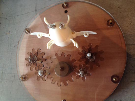
Initially I had planned to make a nice wooden frame with the shopbot, that would enclose a half dome to surround the bug. As I was working on the assembly of the mechanics and the encasing however, I actually felt that the choice of materials worked so well that I didn't want to add these extras anymore. I really like to look of the combination of the wood with the golden fastenings, copper shafts, the transparent acrylic and the tan acrylic. So instead I kept it really simple. Below a work in progress pic to get an idea.
Putting it all together
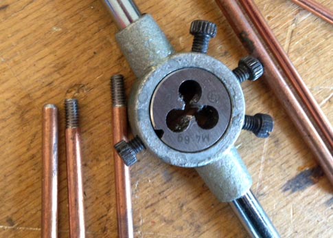
Threading shafts
I'd asked a colleague to teach me how to thread shafts so I could make my own to fasten everything. I'm using copper plated 3mm shafts. You prepare the shafts by making the ends flat and chamfered. Then you add some oil and wind in a thread manually with this tool.
I used this technique for the fastenings but had to use proper screws for everything around the mechanics, because they needed to be really straight.
I'd made a few mistakes with the casing because it's quite easy to forget something (like a wire that needs to go somewhere to be out of sight for example.
Assembly
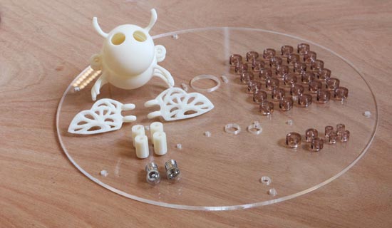
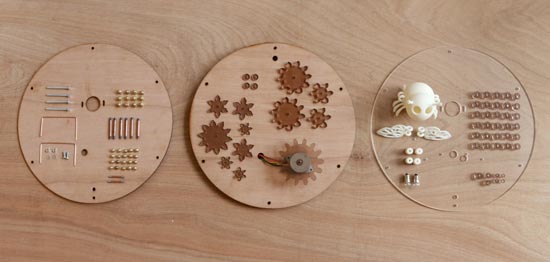
I still had to make some quick changes in the assembly, when I had some details unaccounted for. The camshafts for example needed to be elevated a bit more, so I had to laser and glue some extra beads there. Before I assembled I took a pic of everything to see what I had in the end (excluding the electronics).
For example, I had to keep the camshafts from falling out somehow. I wanted to just bend it, but I could never get it tight enough the way it had to be assembled. So on the fly I made some stops from a tube of acrylic. Cut a hole in them with a 1.5mm drill (same diameter as the shaft) and pushed it on for a good snapfit.
I also really thought about the order before I started assembling because there was some glueing involved. Workflow:
Glue moving parts on the end effector gears together, don't glue cam gear to the bottom gear yet.
Glue decorations to center gear
Polish the bug
Glue elevations to wing rings
Bend and assemble cam shafts
Assemble cam shafts, wings and end gears. Glue end gears to bottom gear, take care that the orientation is the same on left and right
Screw motor onto transparent bottom plate
Screw gears into transparent bottom plate
Test before continuing. Potentionally fasten the screws in the gears on the back of transparent bottom layer
Place bulbs in eyes and mic in hole, fasten with tape
Lead wires through holes in the bottom layers, add connector to motor wires
Fasten board with tape
Fasten bug to bottom layer
Screw backlayers together with beads in the middle
Hang on wall
Power it
It's ALIVE!
Here's a realllllly short clip to demonstrate how (and the fact that) it works :) I will make a nicer one at a later stage.
I improved some of the workfiles based on the mistakes I found (all mentioned above), and added a DC power supply jack connector found on many regular supply adapters. I haven't actually tried these out yet but they are improved versions of the ones listed above.

 The by-nc-sa licence explained