Assignment: Make something big! (Like big bird snapfitkits)
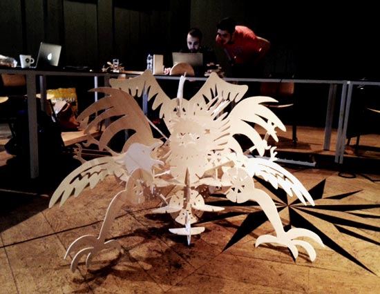
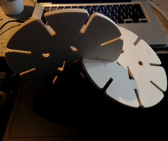
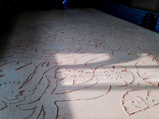
the final product
Big bird kit: preparing the design
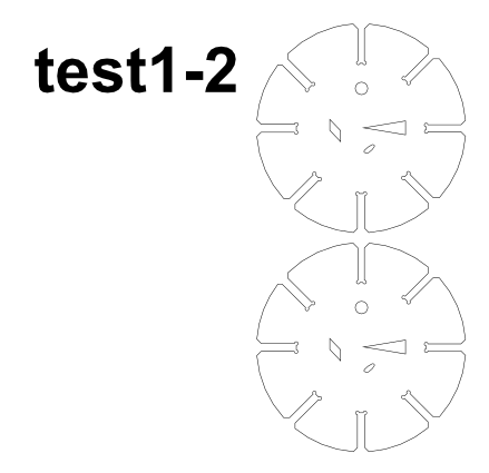
For this week I decided to scale up my bird kit from the Computer Controlled Cutting week into a big bird kit. Here are the steps I took to prepare for the milling job.
I took the original drawing (the one I'd saved before differencing the snapfit notches) and scaled it up to fit into 1220x2440mm sheet. I wanted to keep the relative sizing in check: making the notches thinner, but still going into the parts equally deep relative to their new size. This determines the look of the construction to a large extent.
Then I decided what wood to use based on scrapwood at my fablab: my construction elements would be roughly 18cm diameter circles, so I went for a 6mm plywood. It's light enough to carry elements in the air, it's easy to carry with my ladyhands too. I didn't needlessly want to use a lot of thick wood so I went with the minimum that I found aesthetically pleasing.
Went to get the wood at Schmidt : they cut the sheet so I would have 90 degree angles, which meant it became slightly smaller, I measured to be exact: it's 1218mm x 2346mm.
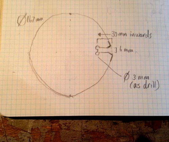
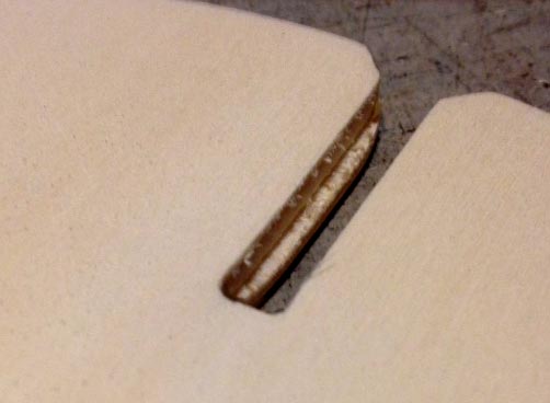
I made test connections with notches between 5.2mm wide to 6.6mm wide to find best fit. I expected that exactly 6.0mm would be best, and it was. But it never hurts to check. I made nice chamfers, and added the dogbones with a diameter of 3mm in the inside corners of the notches.
I chose the 3mm drilling bit, beforehand. This would be workable to make the +/- 6mm notches for snapfitting and is reasonable size to fillet sharper the corners with (the dogbones on the inside corners of the notches.
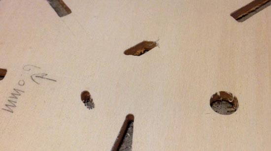
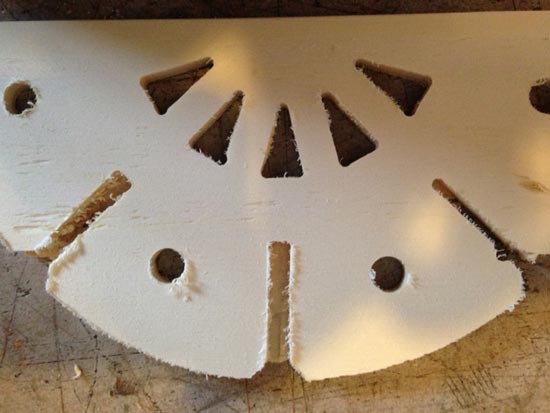
I kept some sharp decorative paths in the test file to see how the machine deals with really sharp corners with a bit that actually has too wide a diameter to make a very sharp corner.
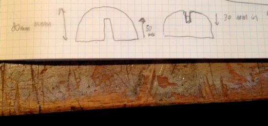
I also calculated the sizing of the feet because they really have to fit neatly and both stand on the ground if they're connected together. *Note: the numbers in the picture are not correct*.
Fastening the material
Because I had a large sheet of plywood, that never stays entirely flat, I did a drilling job to make 12 holes in the sheet where I could drill them to the sacrificial layer. The bonus is that the machine then always knows where they are so you can avoid them easily in your design.
I had to take extra care because there already are screws in the sacrifical layer and the bed itself. I made sure I stayed clear from them for my drilling job, and for extra care I measured their depth. The shallowest one is at least 3mm deep, 3mm and a bit actually. So if I never go more than 1mm into the sacrificial layer for my jobs I should be fine.
I drew circles on my canvas that are big enough to see (10mm diameter) so I was sure not to miss them when doing the layouts for my design. You choose not "surfacing" or "profile" job but a "drill job" in the PathWorks v2 software. This kind of job runs only the center of the circle (not its profile).
After the test job I would notice that the plywood needed to be fastened more so I added 9 more screwholes to keep it down securely for the final job.
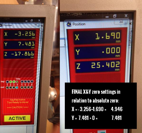
I saved the settings of the X,Y zero relative to the absolute zero. I had set it but then decided to move it in more so I had to take 2 pics and add up the numbers for future reference. I wouldn't be able to finish my final job today as my drawing needs a lot more work. Because there's drill holes for fastening, I can know for sure that my plywood will be in exactly the same place later.
Preparing the machine and test files
Then I imported my files to the file with the drilling job already in it (you want to see them both so you can avoid the screws. I had some problems with the .DXF files I exported from inkscape. It was adding weird open lines where it wasn't supposed to, so the machine gave errors when I tried to run it. solution: import .svg into illustrator, and export as .dxf from there. After that I had no problems.
Then settings:
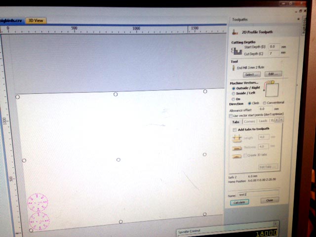
I made a 2D profile toolpath for the test circles
cut depth = 7mm (6mm wood, 1 mm into sacrificial layer
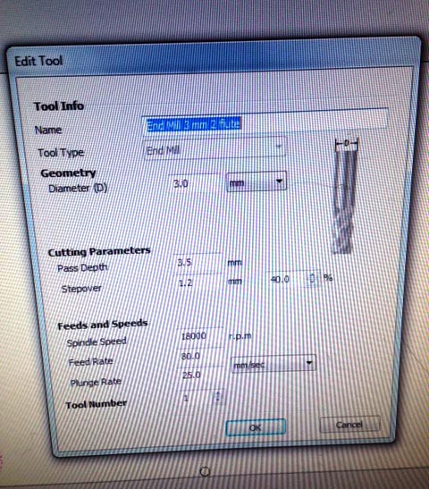
end mill 3mm, 2 flutes
diameter = 3mm
pass depth = 3.5mm > total depth is 7mm, so need exactly 2 runs
stepover is not important for profiling jobs
spindle speed = 18.000 (set manually on hardware dial)
feed rate = 80 mm/s
plunge rate = 25 mm/s
machine vectors = outside. > I chose this because the notches had to be exactly the size I'd set for them in the design in order to define a snapfit size. The drill had to stay outside the vector line. note: the inside decorations will be calculated as such, and they will be cut as if set to inside machine vector, the machine is smart like that.
direction = climb, I'm not sure why but it seemed smart, though I think this is mostly important for pocketing/surfacing jobs.
allowance = 0, didn't touch that
i didn't use tabs
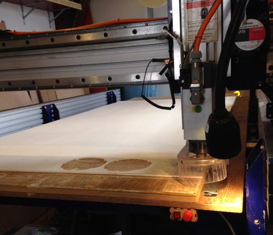
Things I learned from running the test pieces
The perfect snapfit sits at 6.0mm (surprise surprise!)
The sheet was pulled upwards and bulging a bit too much to my liking, reason 1 to add more screwholes for fastening, which I did
The last leg of the job, was an inside notch, that didn't go through correctly. I will run another test job next time, with better fastening and I expect that it will go through properly then. Otherwise adding tabs might help.
Be prepared for a LOT of sanding...and the results will be great, especially the insides will be tough to sand, but the end result will be smooth as a baby butt.
the dogbone of 3mm on the inside corners of the notches disappear beautifully in the design. You can't even see they're there.
Well that was a lot of fun! Now I have to go back into my drawing, add 6mm notches all around and fit as much as I can into my sheet. To be continued.....
Running the entire design job
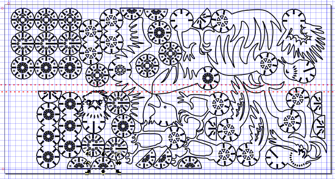
I redid my design with the new measurements to fill the entire sheet of plywood. I used 30mm margins on the outsides, where most of the screws are, and drew a thick bar somewhere in the middle that I tried to avoid. I'll have to rearrange some stuff probably to avoid screws, but I can't do that until I'm in the shopbot software where I saved my drilling path. I gave all the paths a 6mm stroke (= basically 3mm outwards from the actual vector path, and 3mm inwards to be sure I'd have enough spacing between the separate elements.
I was lucky enough to find the shopbot free for some time as the others had already finished or were still working on their designs. I ran the job in about 2 hours (same time it takes roughly to do a similar job on cardboard in the lasercutter :))
I took these steps:
Zero-ed the X,Y and did an airjob of the drill job I'd done before to check for reference. The machine wanted to drill right above the screws so bingo. Safe to go.
Then I tested one element to see if the extra screws fastened the material well enough to avoid getting a faulty cut on the last notch as I'd seen in the previous test. It didn't help at all...
Then ran another element but with two tabs to see if that held enough to make a clean cut including the last notches. Success, this worked. Although not all the tabs held, 3 or 4 per element would have been better.
Then I reshuffled the elements a bit to be sure none of the screws would be in the path of the mill. And selected all & deselected circles of the drilling job. Added tabs and ran the job. Apparently it made a very content sound (I can't distinguish that yet though haha, but here it is for reference.
Fails
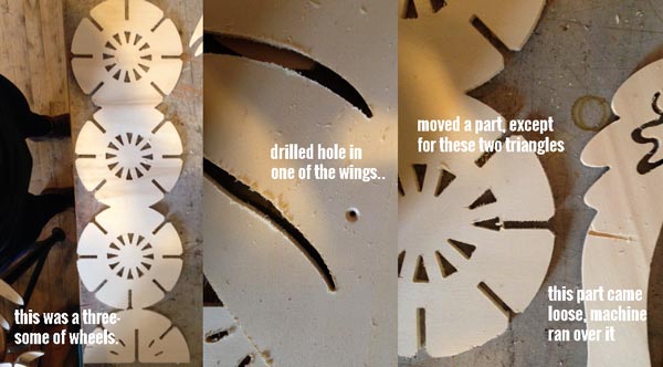
So two tabs weren't enough to hold all the pieces, sometimes it worked, sometimes it didn't, more or stronger ones would have been better (mine were 4 mm long, 3.5 (on run) high. When the tabs break, often the piece had one bad notch because it wouldn't run the last leg of the job properly.
When the pieces come loose it's easy to run over it unintentionaly, ruining the element
One of the screws of the drilling job turned up inside a design element, leaving a hole in one of the wings....
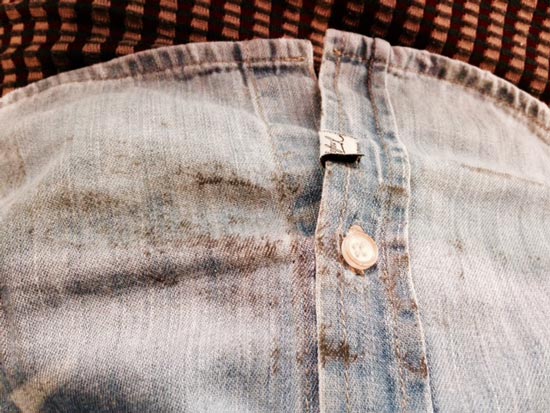
I totally smudged my shirt on the greasy edge of the machine, regardless of Ismael's warnings meh...
If I'd had a copy of the drilling job I could have done a more efficient layout...I guess it could be smart to design the drilling job into your design before going to the machine. And can I say that I just love the way the sacrifical layer looks now :D
Other than that, sanding took forever but I did it with love. The size of this configuration? Bounding box would be something like 100x100cm.
All the things to think of when working with the Shopbot
Some ground rules:
No metals! We don't have a lubrication system to cool it properly
No guessing!Measure twice, and always ask if unsure
Be 100% sure the ventilation is on and on high enough switch 1 = on cupboard, switch 2 and dial on the machine front
Listen and smellThe machine screams if it doesn't like your settings or your material, and it smells when it's burning. Usually burn means feed rate is too slow.
Some terms and concepts
drilling vs milling : drilling = only up and down, milling = down AND sideways
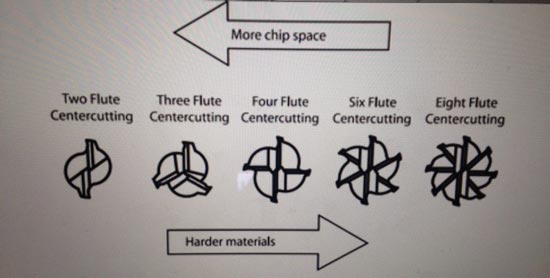
flutes : are legs on a milling/drilling bit. Less flutes = more efficient removal of waste. More flutes = finer jobs, but go slower!
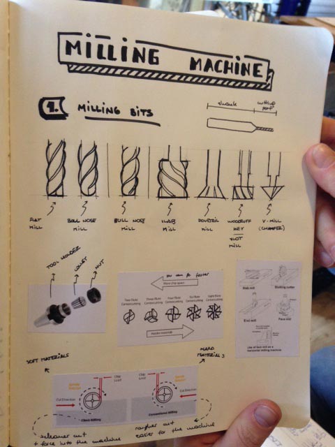
different milling bits
"ball" bits leave a round fillet, flat ends leave sharp corners. Also check out this drawing by Ismael (who has been awesome and patient throughout the learning process by the way, many thanks!)
Overall general tip: do a rough job with a rough job with bigger mill, then refined job with smaller mill.
color of the mill bit Look at the color of the milling bit, if it has weird colors: it's busted, not sharp, and potentially dangerous to use.
conventional vs climbing use conventional for metals. Use climbing for softer materials, nicer finish. This is mostly important for rastering.
upspiral vs. downspiral upspiral efficiently removes waste, but has rough finish on top, you have to sand that off, it pulls your material upwards, so be sure to fasten it. Downspiral: compresses the waste chips, gives smoother finish, but is less efficient in removing waste, easier to burn.
materials: more density = finer detail
High density foam : great for test jobs!
polycarbonate (acrylic)
polyethylene
MDF and MDO
Chemical wood
Other woods
wax : great for very fine 3D modelling jobs
aluminium : has to be manually lubricated to cool! take care
Rules to work safely and efficiently
Fasten your material! Use screws, make sure you avoid them in your job. Do a drilling job to dill holes and let machine remember where they are
double sided tape works for wax because it's so soft
make sure it's at a straigh angle, parallel to the bed
for fine jobs: it's better to keep the bed still and move only the head from left to right, requires less power and is more stable. Rotate your material and drawing if necessary.
pull your long hair up
don't wear clothes with loose hanging or wide bits that can fly into machine
wear hearing protection
wear goggles
Attaching the milling bit
Choose the right collet, make sure there's no play, but don't force it in either. If you squeeze the collet it should hold the mill bit tight.
Your nut should never touch the material! It will burn straight away. Carefully measure that your milling bit is sticking out enough to avoid this
Choose a milling bit that is long enough to go through the material.
Choose the right milling bit: only a sharp end is for drilling. A bit that is sharp all along the grooves is for milling.
Some collets indicate on the inside how far it should go in at least. Check that
use the perplex plate under the machine to measure how far the milling bit is sticking out.
Measure the thickness of your material. Exactly. Set the settings so that the max cut depth goes 1mm (no more) into sacrificial layer.
Lower skirt in the back of the head. Take care of your fingers when unscrewing the milling bits with the wrenches.
make super sure that the milling bit is sitting tight!
The Software
First start the machine, then the software. Disobey and it will give you trouble. And vice versa. When finished: stop software then turn off machine.
PartWorks to prepare paths for 2D and 2.5D : prepare .DXF files for it (don't export from inkscape. Open SVG in Illustrator and export as dxf from there.
for 3D and running the job: use shopbot 3
1. Start in Shopbot 3
Open shopbot 3.
hit the XY on the top menu to go to the "absolute" x,y zero of the machine.
Hit "K" to open control to move the head
arrows for X,Y axes
pg up & pg down for Z axis
hold ctrl to go faster
toggle "fixed" to make smaller movements
HIT SPACE ANYTIME TO PULL HEAD UP FROM MATERIAL, also when running. It will keep spinning though.
use arrows to move along X,Y axis, go to the place where you want your origin. Take a picture of x,y values!
Go to menu > Zero > Zero axes X & Y to set your new origin
set the Z: Get the metal ruler out of the head, and make sure the alligator is connected. Touch the milling bit of the metal ruler, a green ball should appear to show it's sensing the metal to the drill bit.
put ruler on the material before milling, or put it on a higher object to run an airjob first.
Find the Z button in the top menu bar, OK. The mill will come down to touch the metal twice. Your Z zero is set.
hit "K", input zero for X and Y and hit GO TO, to go to your origin.
start the spindle to warm up the gears using the key.
2. PartWorks
Open new file in PartWorks
Set dimensions of your material
import your DXF vectors, or draw a drilling job if necessary.
settings: find the right milling/drilling bit in the drill settings
revolutions: is the spindle speed. Don't set it in software but on the bottom of the machine itself. 18000 RPM is max, use for softer materials, go slower for hard materials. Go slower with milling bits that have big surface.
feed rate: how fast the head avances over material in mm/s, 80mm/s is good starting point for plywood. Listen to the machine to be sure! If it cries, change it. Hit space bar > insert command > change top left value > enter > esc > resume
plunge rate: in mm/s: how fast mill approaches material the first time it comes in. Max 1/1 relationship to diameter of the mill.
stepover (for rastering/surfacing/pocketing): how much one trace overlaps with the previous trace. 48% is a good starting point. The lower the stepover, the more rounds you need
ramp: if you're using bigger bits (lots of surface touching the material), come in at a ramp of 25-45 degrees. To make sure bit doesn't break.
put orientation on bottom left (grey cross on canvas
rotate and move around the vectors.
create a milling job for each kind of job: profile (lines), pockets (surfaces) or drilling jobs (holes). You do this by selecting the paths that belong together in thesame job, then generate toolpaths for each group
For pockering: if you want to surface down an area (make the thickness of the wood thinner for an area, might be easy to draw a rectangle to specify it. Is easier than polylines
Settings in PartWorks
select your vectors
toolpath: choose the right job
give info about the milling bit you chose
start depth = 0 (where you start relative to Z)
cut depth: how deep it should go in total. Go 1 mm deeper than material
ETCETERA (see concepts above for explanation)
finally: give it a clear name and hit CALCULATE
review the 3D job to check
save toolpath in your project folder
3. Go back to Shopbot software
file > load OR import your newly created toolpath
turn on dust collection!1) on cupboard 2) on machine
first turn on the spindle!
then run your job
stay with it at all times. Hit space to pause (bathroom break.
Run airjobs first, always
Done? Turn off spindle. Turn off software. Then turn off machine. Clean up your shit and vacuum the bed.


