BAMBOCO
An off-the-grid vertical herb garden
For the final project, I want to make a hydroponic herb garden for my balcony.
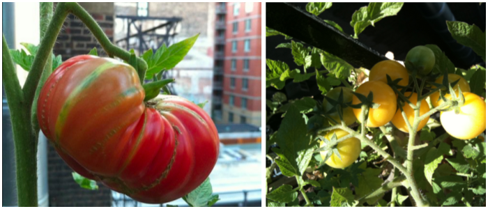
Six years ago, I grew my first hydroponic herbs and tomatoes on a New York firescape with great success.
Last year, I made another vertical garden, by hanging plastic gutters filled with soil on the fence of my backyard in Lisbon. This time I used soil and was again growing all sorts of herbs.
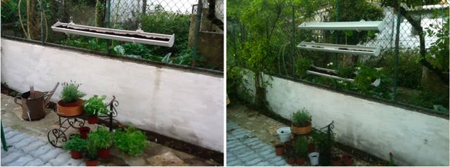
Everything was going swell until spring time arrived and temperatures started to rise. Since I was unable to water it everyday, all my herbs were dead within a month.
So this year, I decided to use Fab Academy to design a new version of a herb garden (aka, one where plants can stay alive) – this time i'll combine hydroponics with a vertical system made with natural/recycled materials and will power it with a solar panel. A small DC air pump will bring the water up to the top level; a ph and a water level sensor will help control the nutrients that feed the plants.
The system will be off-the-grid -- veggies and herbs will grow in a small space, without the need for electricity/water sources.
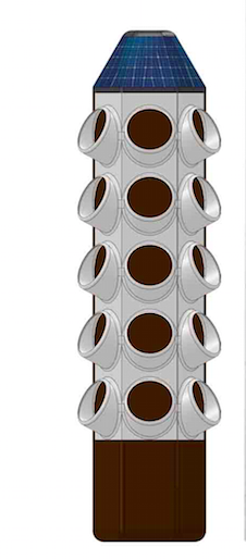
This is the model that inspired me, designed by the hydroponics master João Henriques from Biovivos:
And here are some bambu gardens -- which made me believe I could make a more eco-friendly version of the original model.
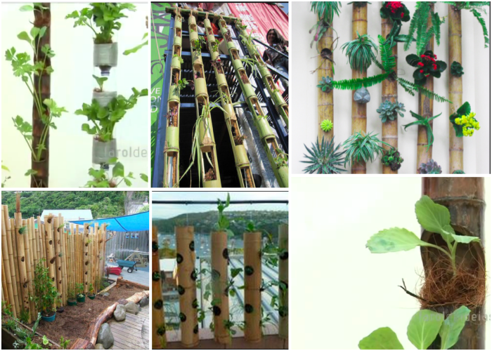
GROW TUBES
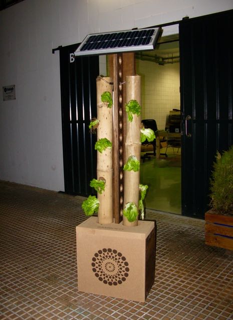
I used two bambu tubes -- 10cm diameter, 110cm lenght. I cut five 60mm holes with a cranian saw to create "windows" out of which the plants can grow. The tubes will be parallel to each other, and their weight is supported by the thick cork slab at the top of the water container. I stuffed the tube with a mesh of coconut fiber which I throughly washed with water (coconut fiber often has excess salts which are prejudicial to the plant's growth).
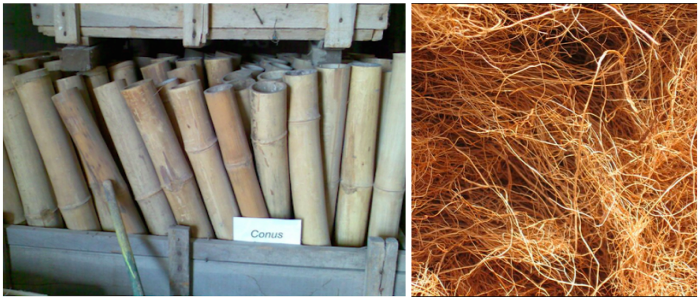
WATER CONTAINER
I've got a 30 liter water container that is 37cm high. This is the minimum height needed to make the water rise up to 130cm.
The water container is then covered by a 40mm layer of cork, so the water stays cool inside.
Initially I planned on making the container out of recycled HDPE. I made a small test melting and molding plastic bottle caps in an oven (about 25min at 175ºC) and it worked quite well. However, when I realized that I needed quite a big container for the system, I decided to just go buy a plastic bucket with the right shape.
This is the small bowl I made to test the melted plastic:
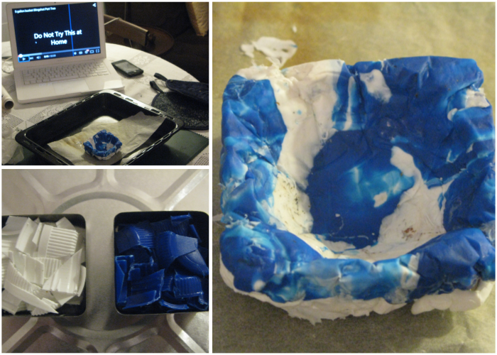
And here is a great youtube video to learn how to melt plastic:
MAIN STRUCTURE
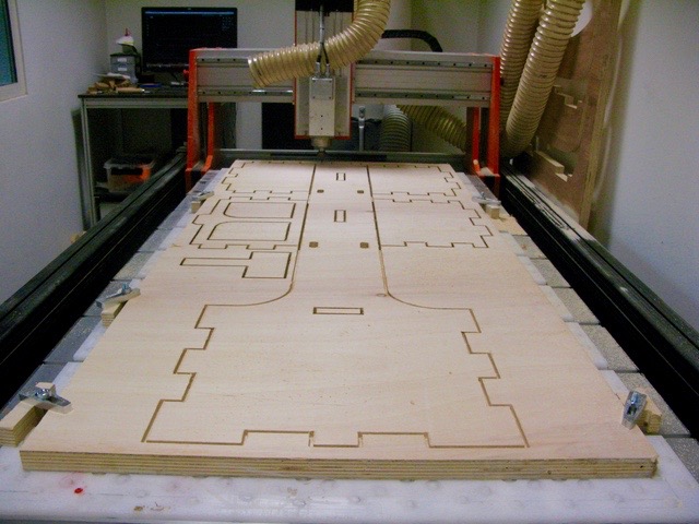
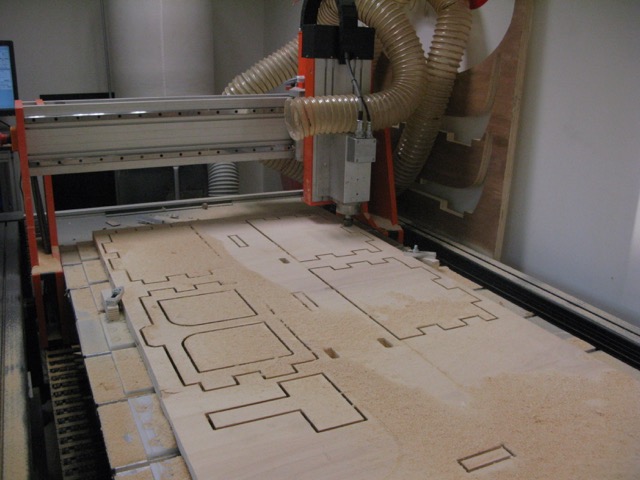
The structure for the vertical garden was milled off a 30mm plywood sheet. At the top, the base for the solar panel was lasercut MDF, which I covered with acryclic paint.
FIRST PROTOTYPE
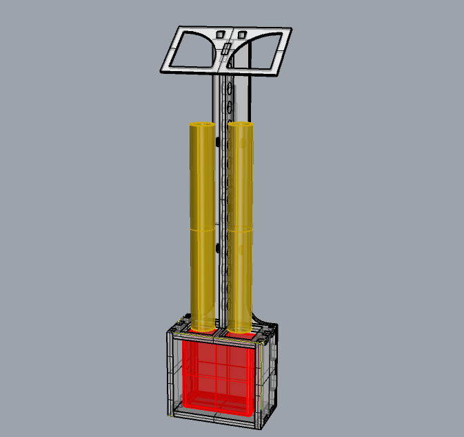
This was the first sketch I made of the system:
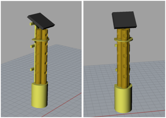
And the first real-size prototype made with bambu and cardboard:
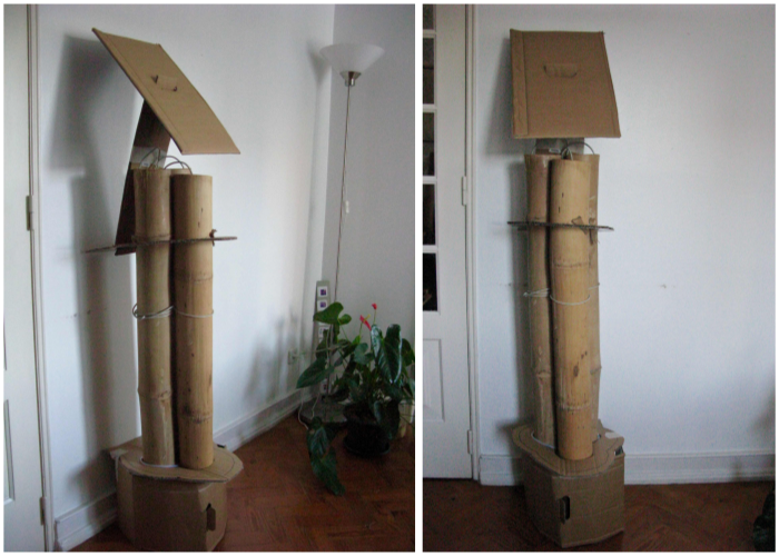
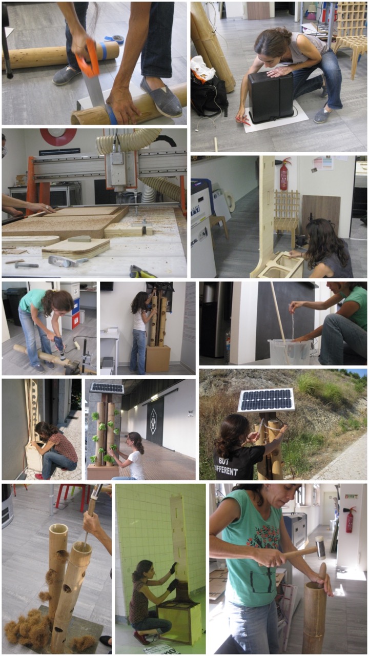
Here are some photos showing the making of the structure:
USEFUL RESOURCES:
GardenBot, is an entire gardening network that monitors the soil and creates charts that allow you to see the world the way your plants do.
Windowfarms, an open source community developing hydroponic edible gardens for urban windows.
3D ponics - A great source of ready-to-3Dprint parts for hydroponic systems.
And some useful instructables:
Vertical hydroponic farm Solar hydroponic system with pumpFINAL LIST OF MATERIALS
ph sensor
sonar sensor
fabkit
2x 600 farat supercapacitors
DC air pump
solar panel 20W, 12V - solar panel specs
water pipes and joints (4mm, 8mm, 16mm)
2x bambu tubes 120cmx10cm
500g of coconut fiber
1x 30mm sheet of plywood
1x 3mm MDF piece (to lasercut the base of the solar pannel)
1x 40mm cork slab (to serve as cooler to the water container)
DIGITAL FABRICATION SKILLS USED
CNC Milling
PCB milling
Vinyl cutting
Laser cutting
3D printing
Programming: Input/output devices (2 sensors)
SOME PHOTOS OF THE FABRICATION PROCESS
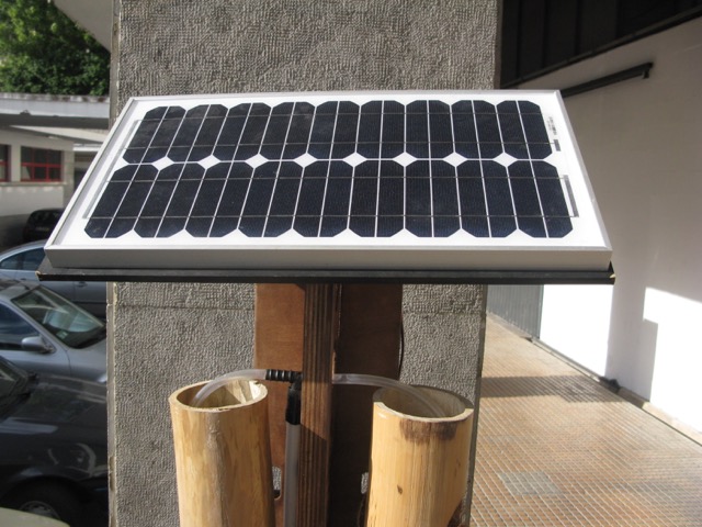
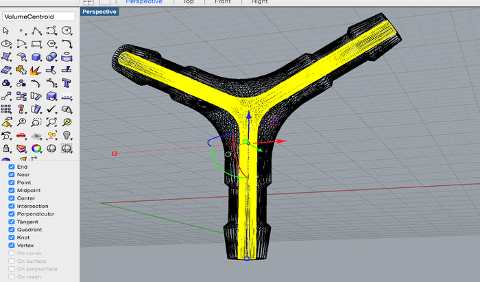

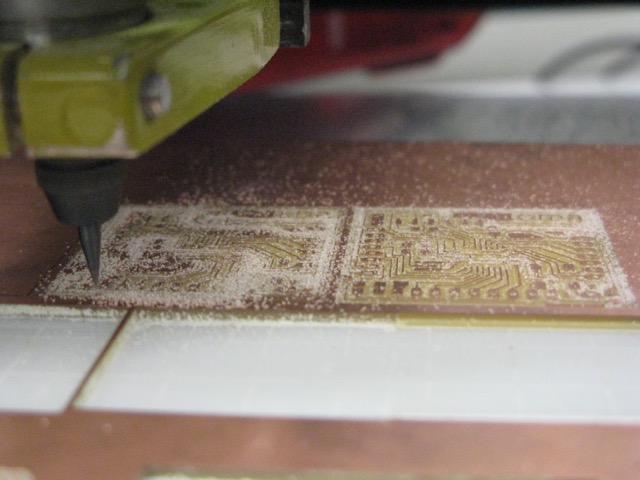
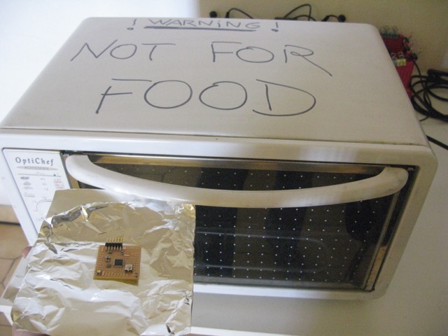
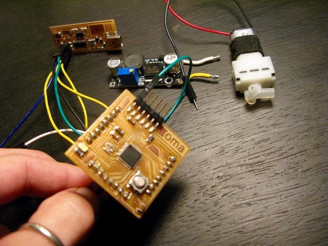
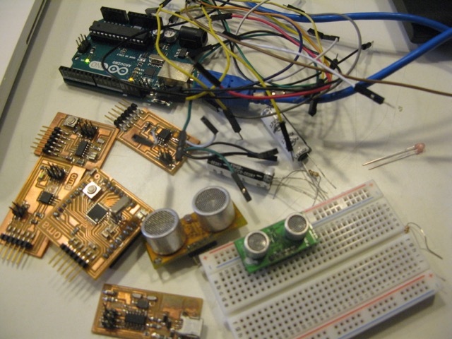
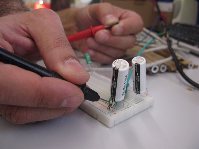
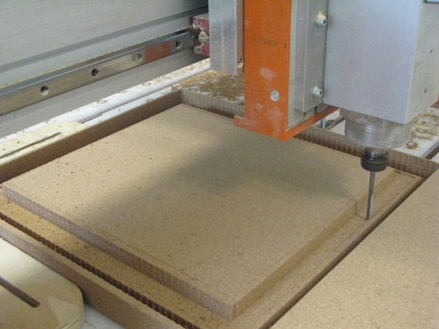
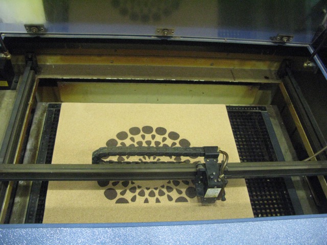
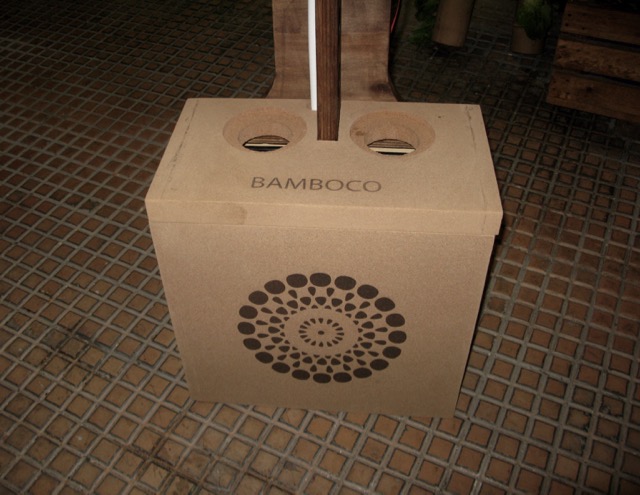
And here is the finalized vertical garden:
MORE ABOUT THE PROJECT
COCO FIBER
Its reusable, sustainable, easy-to-use and a by-product of another industry
As a hydroponic medium, coconut fiber not only boasts some great ecological qualities but it also has outstanding water and air holding capacity. It can hold eight to nine times its own weight in water without becoming anaerobic-even when saturated it can still hold on to around 22% air-beating even rockwool (around 10% air holding capacity.) Coco coir is therefore a forgiving hydroponic medium, allowing roots access to enough oxygen even when watered a little too enthusiastically with a warm nutrient solution. This makes it the ideal choice for beginners.
Coco coir also boasts antifungal and root promoting properties and can suppress and protect plants from dreaded root diseases such as pythium and phytophthora.
Slowly but surely, grow rooms the world over are converting to one of the few completely organic growing media available to hydroponic growers. It may even soon surpass rockwool as the most popular medium used by hydroponic growers because of its higher environmental friendliness and excellent water and oxygen retention.
Good quality, hydroponic grade coco coir will not have a high salt content, but you should always flush it through with a low EC nutrient solution before use until no more tannins are coming out. Tannins can easily be seen as they stain or color the water brown.
After rinsing for the first time, coco coir has the tendency to clump together. To make sure that your roots will receive all the oxygen that they need, break it apart with your hands before placing it in your hydroponic system.
CHOOSING THE PUMP
What I needed -- an affordable quality pump that provides a reasonable water flow at 125cm head and with the lowest energy consumption possible. The options were a submersible water pump or an air pump (coupled with an airlift system)
A)WATER PUMP
Step 1: Determining Desired Flow Rate
Most ponics systems flow through a single loop allowing a single pump. A flow rate near 100 GPH is sufficient for grow beds loop up to 120 feet. If you have multiple grow-bed loops, then 100 GPH is needed for each loop. Flood/drain beds needs 2 to 4 cycles per hour.
Step 2: Calculating System Head
Measure the vertical distance from the "top" of the water in the pump tank to the pump discharge pipe. A typical requirement is 100 GPH @ 3 feet.
Step 3: Pump Selection Considerations
• Continuous vs. intermittent pump duty cycle increases pump life, plus no need for a timer or level control.
• A rule of thumb is that an average pump will last 2-4 times the stated warranty period.
• Best to buy a backup.
Step 4: Is A Foam Filter Needed?
The objective of a filter is to keep objects/grit out of the pump.
• While great for ponds, a foam filter in "ponics" systems is a maintenance headache as good place for algae to grow.
• If you endeavor to have clear water... you will likely need a separate pre-filter, so a foam filter is redundant.
• Green water algaponics systems require a vortex pre-filter; a foam filter would only clog with desirable algae.
• Micro-algae will not hurt a pump unless it stops water flow.
ATTENTION
"Maximum Flow Rate" is meaningless because it is at ZERO head.
"Maximum Head/Lift" is meaningless because the flow at that height is only a trickle.
B) AIR PUMP
At the end, I decided to abandon the water pump idea, as I wasn't keen on keeping any part inside the water all the time. The airpump seemed like a more durable system with less energy consumption.
From the Hydroponic Window Farm Experience
The founders of windowfarms.org spent a fortune on water pumps early on in the project and they broke down and could not cope with the nutrients and junk clogging them up. They require much bigger reservoirs and pump the water much quicker than airpumps.
"An air pump is cheap and easily available and, with an airlift, it can pump to either 1 ft high or 10 ft with only tiny adjustments and tiny reservoirs. The electricity requirement is small too. Another thing is that the air pump can be far away from the plants."
AIRLIFT SYSTEM
An airlift is obtained by introducing compressed air at the bottom of a pipe partially submerged in the liquid. It generates a vertical movement of the fluid (often water but sometimes a mixture of liquids and solids). The principle is that the presence of gas bubbles decreases the average gas-liquid density and creates the driving force of the pump.
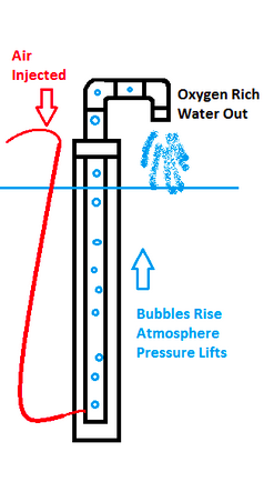
• The only energy required is provided by compressed air
• This air is usually compressed by a compressor or a blower
• The air is injected in the lower part of a pipe that transports a liquid
• It usually bubbles into another larger diameter pipe
• By buoyancy the air, which has a lower density than the liquid, rises quickly
• By fluid pressure, the liquid is taken in the ascendant air flow and moves in the same direction as the air
"What is excellent about the air lift system (once working) over the water pump system is the reduced cost of the setup, simplistic design and setup eliminating the top reservoir and having to seal and water proof the system, virtually noise free (no loud water pump), not having to worry about running the pump dry and damaging the unit, and the reduced operational cost (water pump consumes 80.5Watts versus air pump at 3.5Watts). Not only this, but the water pump system also suggests using an air pump in addition to the water pump to aerate the water so it does not become stagnant and reduces mold/algae from standing water in the bottom reservoir."
"Our bottom reservoir is a glass cylinder measuring only 4” diameter, however, the container stands 13.5” tall. When this is filled to 9.5” the max lift we recorded was 5’ 4”. When filled full at 13.25” we achieve an 8’ 3” lift, though 7’ 3” appears to be the optimal level for this water depth. Also as others have stated, keeping the air lift tube as straight as possible, especially into the reservoir helps achieve better lift.
DC AIR PUMPS
These were not very easy to find, unless you have a month to wait until they arrive from China. I scouted several pet shops in Lisbon to try to fin one of these, but I could only find AC pumps for aquariums.
I then found a few for sale on Amazon in the UK and Germany which could arrive in Lisbon fast enough.
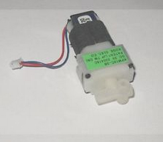
At the end, I chose a little 3V, 440mA air pump , which cost a mere 7 euros.
SOLAR PANEL
I am using a 20W, 12V solar panel.
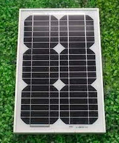
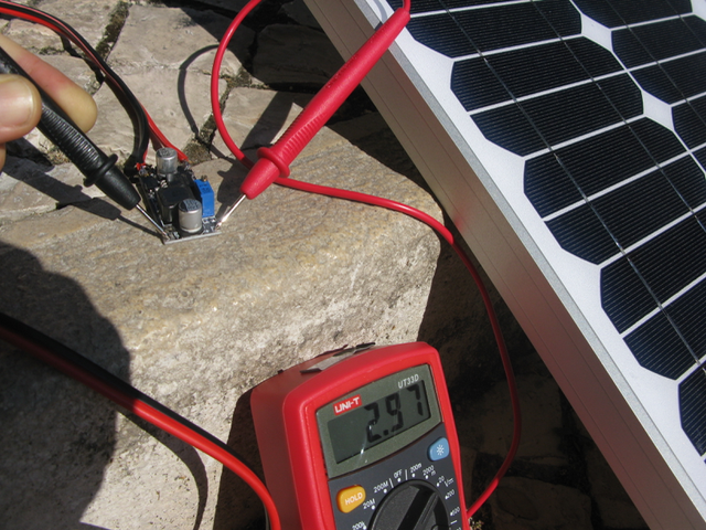
I connected it to a DC to DC converter, which turns the 12V panel into the 3V the air pump needs.
ENERGY STORAGE: SUPERCAPACITORS vs BATTERIES
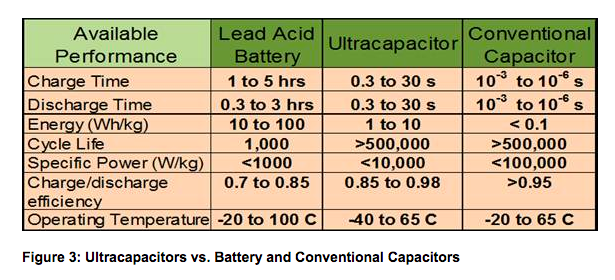
There are fundamental differences in the characteristics between ultracapacitors and batteries with regard to energy density (WattHours) and power density (Kilowatts):
- Batteries can store a lot of energy, but are limited in terms of power density and response (ability to discharge and charge quickly).
- Supercapacitors have the opposite characteristics: limited in terms of total energy storage, but “power dense”, with an ability to discharge high levels of power quickly and re-charge rapidly. In fact, they charge/discharge at least 100 times faster than batteries.
A) BATTERIES
Batteries are the "weakest link" in a modern solar system. They're heavy, full of lead and sulfuric acid, require regular maintenance, and will wear out sooner than any other component. Most complaints on older systems are due to old batteries.
I will try to stay away from batteries and focus on making the air pump work a few hours per night with the help of supercapacitors.
B) SUPERCAPACITORS
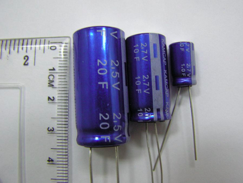
Supercaps, bridge the gap between conventional capacitors and rechargeable batteries, offer performance characteristics that are well suited for energy-harvesting environments. They can provide capacitance values up to 10,000 times that of conventional electrolytic capacitors. Moreover, while in the past supercaps could only provide about 10 percent of the energy storage density of chemical batteries, new supercap chemistries and architectures are yielding higher-density energy sources that can be charged relatively quickly.
FUNCTIONS:
Secure power - Provide reliable interim power, even if the primary source fails or fluctuates
Energy storage - Store energy from low power sources, enabling support for high power loads
Pulse power - Supply peak power to the load while drawing average power from the source
BENEFITS
Reduces the size & weight of the battery / power source required
Improves run-time & battery life, particularly at cold temperatures
Enables more power-hungry features, being used more often
Can remove the need for a battery & harvest energy from clean sources
Protects against accidental power loss or fluctuations/interruptions
Doesn’t need to be replaced like batteries (unlimited discharge cycles)
Environmentally friendly & safe
USEFUL LINKS ON SUPERCAPS:
I saw this video showing a 2600 farad supercap powering a small DC motor for 24h. And this is when I started to believe there was a chance my small air pump would work for a few hours during night time.
DC motor run by supercapThis instructable is a great resource for building a supercap charging circuit:
Measuring a supercap's storing capacity
Amp-hours, as used in describing battery capacity, does not apply to capacitors. A battery has a relatively flat discharge curve. That is, with a constant load on the battery there is a time period when the output voltage changes very little. Then as the battery is running out of charge the output voltage drops quickly. In very round numbers, a battery's amp-hour rating describes how long the output will be in that slowly changing flat spot.
In a similar situation, a capacitor does not have that flat spot. Depending on the type of load, the discharge curve usually is either a downward sloped straight line or exponential curve. As above, you can calculate the total energy in a cap and relate it to the total energy in a battery, but the discharge characteristics are so different that "amp-hours" does not apply meaningfully to a cap.
What you can do is determine the minimum capacitor voltage you need to run your circuit and work from there. For example, if you have 5 V on the cap and you are running a circuit that will function down to 3 V, like most CMOS logic chips, and you know the current the circuit draws, you can calculate how long it will take the cap to discharge from 5 V to 3 V.
Ok, so how many supercapacitors do I need then?
To determine how many cells are required in series, divide the maximum application voltage, Vmax, by the maximum allowable cell voltage. The maximum allowable cell voltage is determined by life and temperature considerations. Nominally, this can be assumed to be 2.5 volts per cell.
Here is a useful supercapacitor online calculator that helps you estimate the operating time for each cell:
Capacitors - series/parallel connection
Organic electrolyte supercapacitors are rated in the range 2.3V - 2.7V cell. Since in most applications the required voltage is above 2.7V multiple cells will need to be placed in series.
Series connection - When placing cells in series the overall voltage is increased directly by the number of cells in series.
Example: 4 cells (rated at 2.7V each) connected in series will have a maximum voltage of 10.8V.
Depending on the required energy there could be a need to then place multiple cells in parallel.
Parallel connection - Placing cells in parallel will not affect the voltage.
Example: 4 cells (rated at 2.7V each) connected in parallel will have a maximum voltage of 2.7V.
Parameters for sizing the right super capacitor:
Maximum Charged Voltage (Vmax), if different from Working Voltage then also (Vw)
Minimum Voltage (Vmin)
Required Power (W) or Current (I)
Duration of Discharge (td)
Parameters for life degradation:
Duty Cycle
Required Life
Average Operating Temperature
More at:
http://www.linear.com/solutions/Supercapacitor_Charging
http://www.printedelectronicsworld.com/articles/1921/using-a-supercapacitor-to-manage-your-power
FABKIT - version 0.4
I made a Fabkit v0.4 to control the sensor system: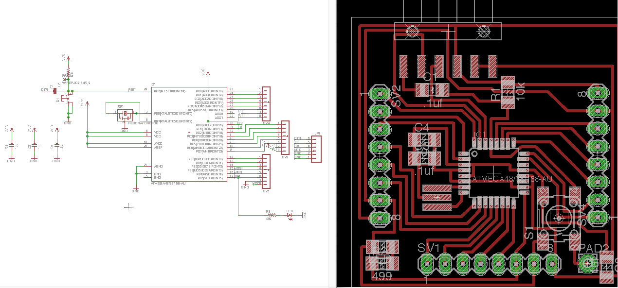
SENSORS
1) A sonar sensor to measure the container's water level. When it is too low, an LED will blink.
2) A ph sensor measuring once a day will control the nutrient status in the water container.When ph goes under 5, a LED will blink (at a slower pace).