Once in fair at village I was enjoying bull race. But suddenly an accident took place near by me. I was so much scared Bull suddenly became
uncontrollable.Also many times that bulls unable to stop themself even after crossing end line. I was safe but I lost in thinking that if it is
possible to controll bull remotly? But I was just 15, was in school. At that time I was in school and I didnt know about FabLab. Now then years
have been passed. Now it is not imagination only.Im trying to make it almost possible.
Project Idea
I want to make such device that will able to controll bull. The idea behind this, I decided to use DC motor thas has low starting tourq and speed
also. Then remote circuit, I thought to use RF module initially. That means Rf module will able to communicate between two boards. This will operate
motors that I will attache to the rein of bull.

Once It works, I have to install it on neck of bull. So if bull became uncontrollable using remote one can turn ON and OFF motors so that rein get
pull as done by manually. This is application area.I decided to use Decoder and Encoder IC. Initially it looks very easy because i have made wirwless
circuit for home appliance but on through hole PCB. This is first time I am going to use SMD.
Mainly I have to work on circuits more than machanical part which is quite easy. It is just fixing the motors and attaching it to rein.electronics
circuit till now I was ussing through hole componants. During fab academy i used smd. componants. For final project I thought of the use encoder and
decoder IC. Which eshtablished wireless communication, transistor circuit and relay circuit. The thought behind that was I will operate DC motor by
transister circuit to operate relay and Decoder and Encoder ICs for remote communication. I made block diagram for the electronic concept I though
about
Also study the theoratically how it will implement. I study the datasheets for ICs and for transistor. Because for designing electronics circuit using
smd componants need to know pakages. I decide to used transistor as switch to oprate relat that further connect supply to motors connected to it. Now I got clear idea about electronics design. I try this circuit on breadboard and then went to design on EAGLE.
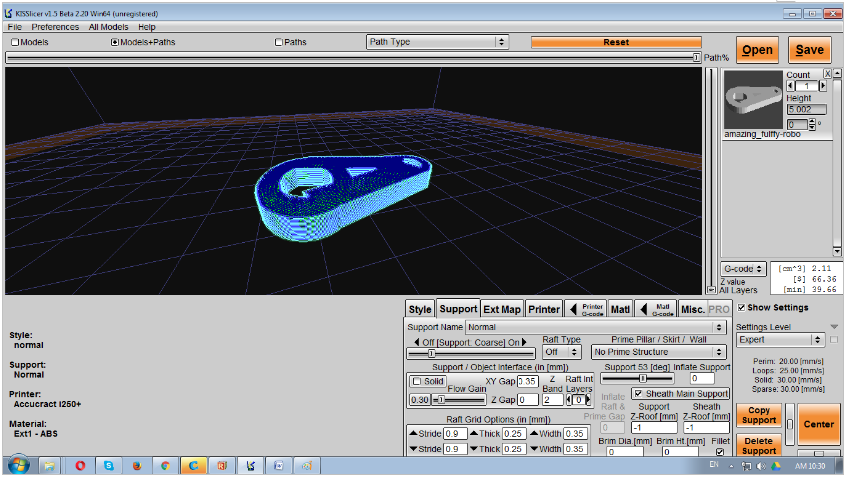
Electronic Design
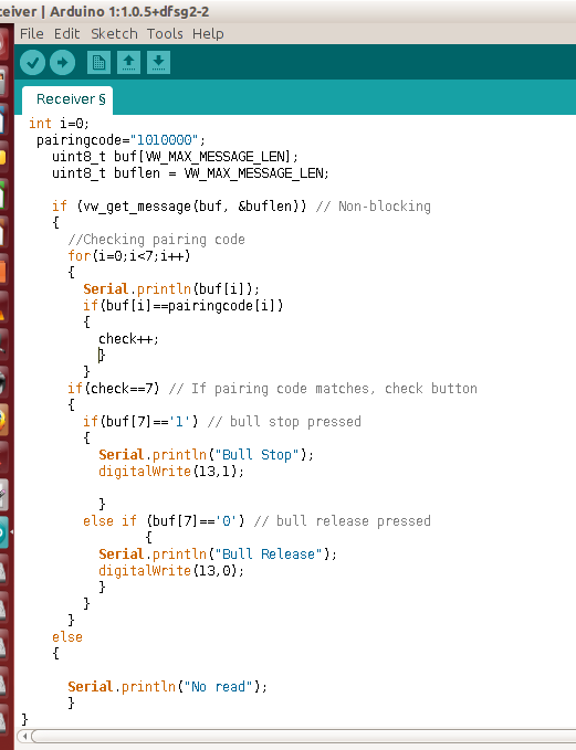
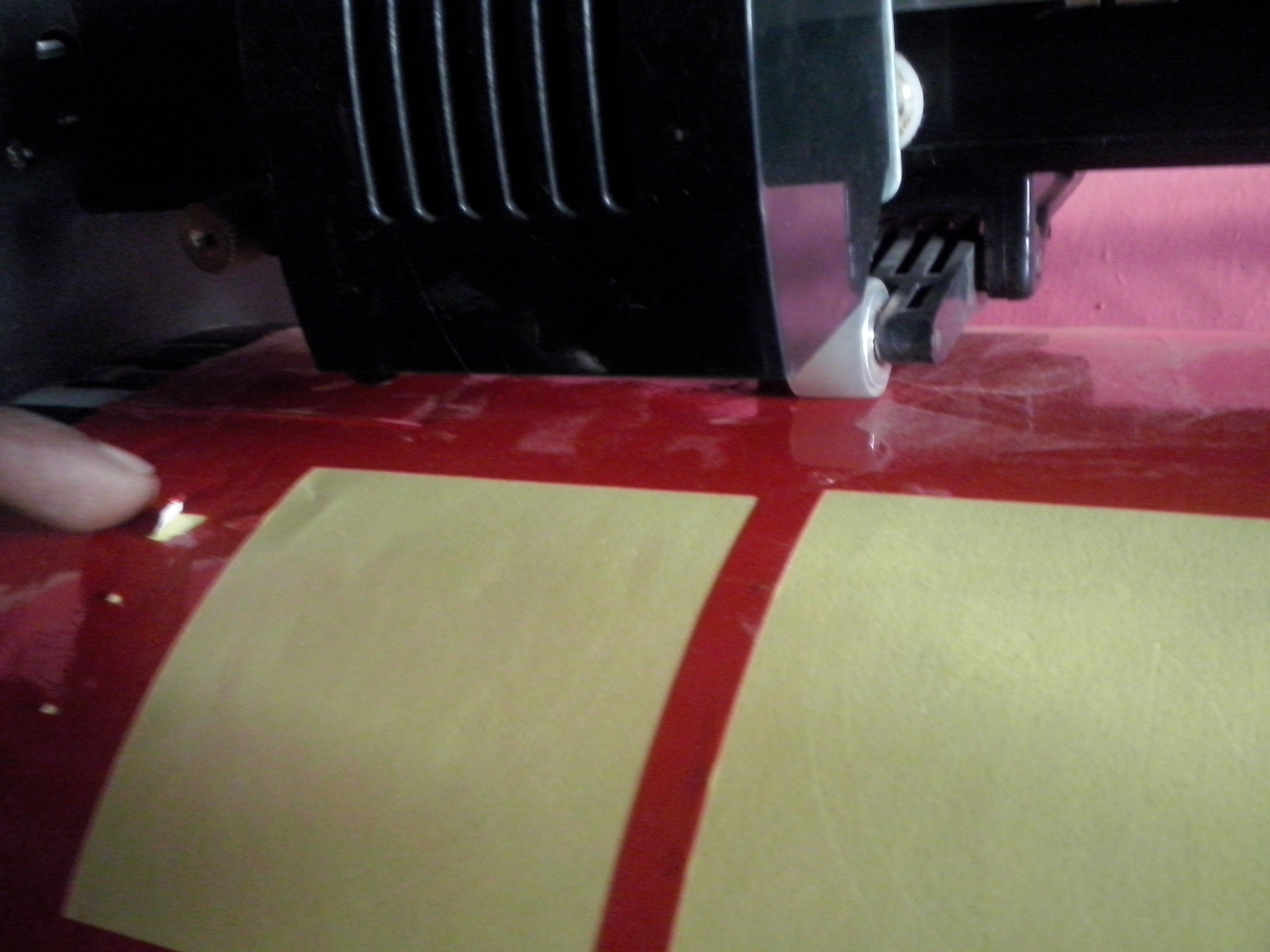
In Electronic Design I learnt to use Eagle software using that I designed transmitter board and receiver board.here one can get EAGLE FILES for board design. I milled the board on modela and implement the board.
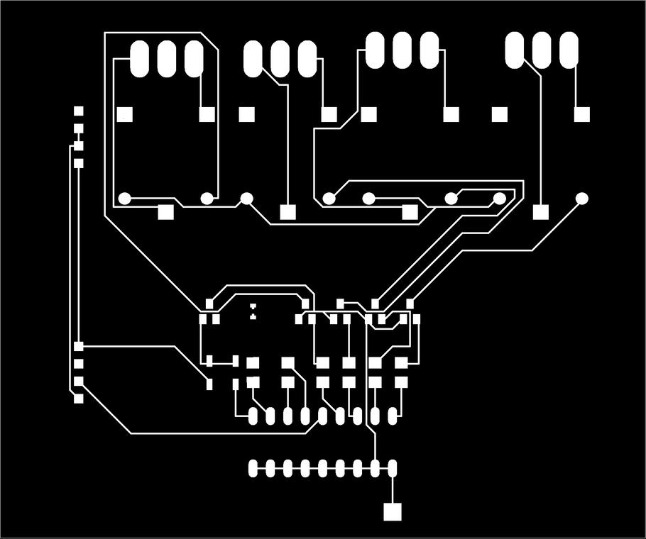

I have soldered componants on it. But problem is, it does not work at all. I took tryels and trying to fix it many times. But it still not working at
all. I encountered a problem that receiver is receiving a signales. Red light in above circuit indicates valid communication between two boards. I
though its done but it was not like that. somthing is missing there and Im working on that from so long time but not able to fix it. I trash the board
while working on it so long. So made new board.Once was installing solar system at Vigyan Ashram with service engineer, at once at evening time I talk
to him about problem in circuit board. He guide me tell me to check componants pakages I have used. So as per his advice I checked whole board
starting with circuit design, check all componants datasheets.
Checked the all componants ance again. Whole things were ok except that transisters I have ordered was wrong. So I need to replace it with
right one. I changed that IC finally it works. I am so happy with that now felt that my final project is under coverage. Until then I damage the
board.
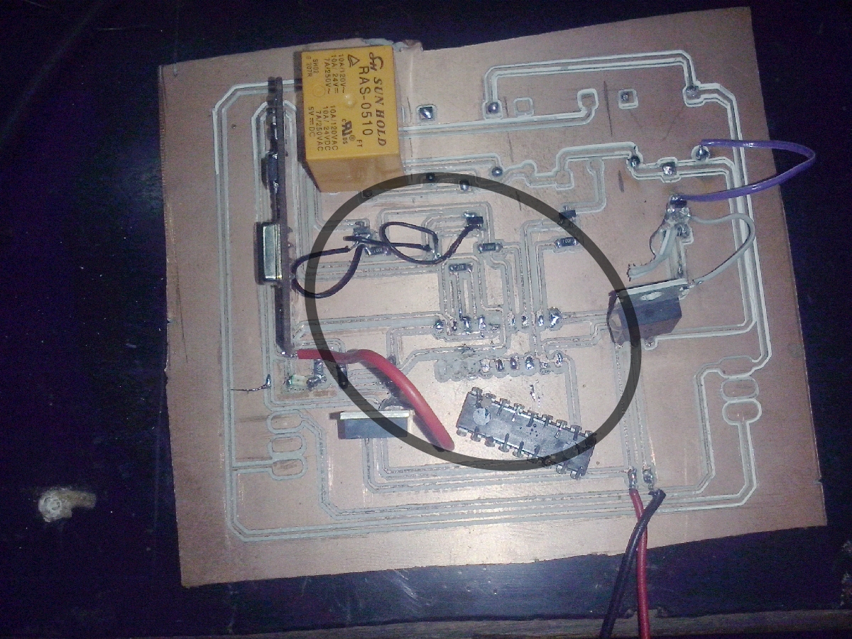
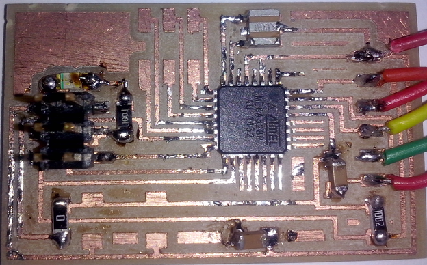
So I again design new board rectifying all mistaks and tried to make it less bulky to do suhas helps me.New Board Design I almost get succeed with board design and componant soldering on it. I sucessfully done by this method. Problem with this board was it is unable stay longer their componants. I lost two ICs on this boards. I dont know why initially it works after sometime it automatically stop working. Unfortunatly I dont have photograps of working board
 |
 |
Old board |
 |
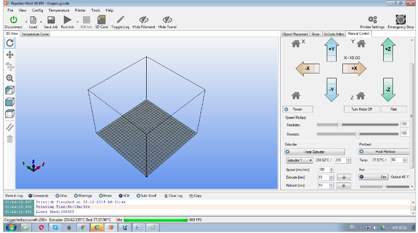
Electronics production
Download the files
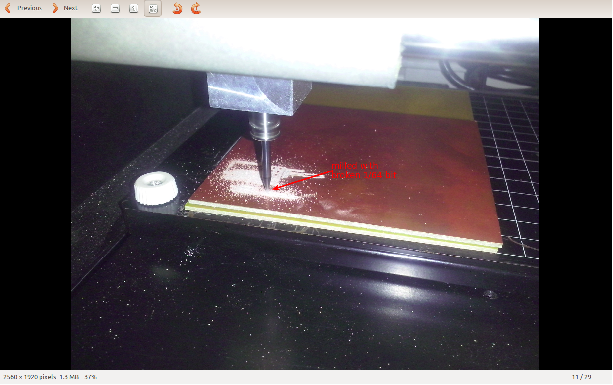
Download the files to mill. Get the files from Fab Academy site. But the problem was I did not get 1/64 bit to mill the board. All bits were broken. But then I milled the board with broken 1/64 bit
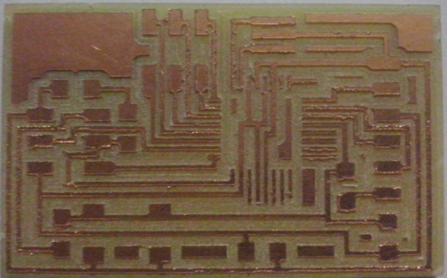
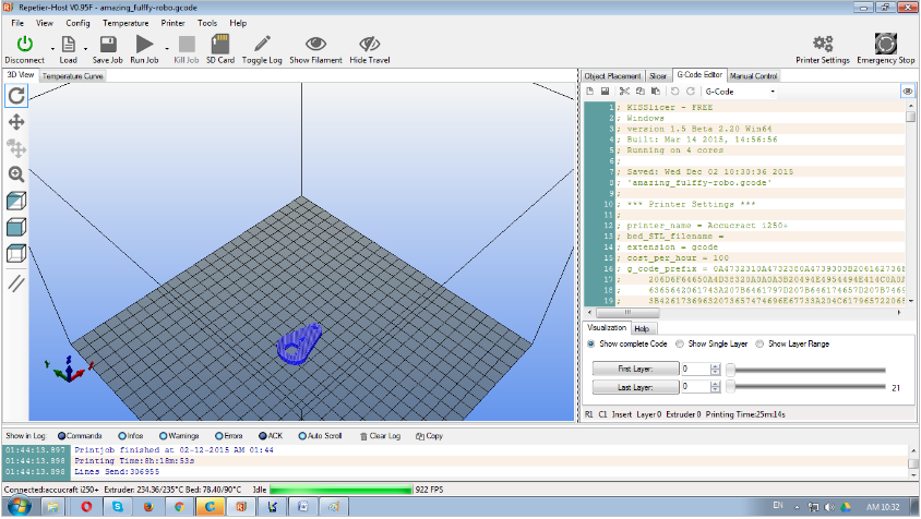
Board is ready with soldering the SMDs. Most difficult part to soldring was ATmega328 IC which took to much time. Finally I checked the board. At
the end I again checked all traces shorts. Microcontroller terminals the board is ready for being program.
Burning the Bootloader.
I can use either an ATmega168 or ATmega328 this board. Just make sure I have to burn the appropiate bootloader. As I used atmega 328p. I dint
understand bootloader clearly. But in simple line I understand bootloader as it is small program that allows the sketches to being upload on the
IC to program. So first target was to burn bootloader on blank IC. I reffer datasheets for microcontroller and get the below info.
ATmega328 Pinouts
I have to an in-system programmer (ISP) but the FabISP I made in class was not work any more. Since Im using Arduino board instead so now I felt that
I can use Arduino IDE and board. And I found on the net that the easiest way to get the bootloader onto the board is through the Arduino IDE
so I thought to use. For this I reffer the Tutorial available on internet. I made set up of Arduino IDE by fallowing tutorial.
Here is the boards.txt file to make custom setup in the arduino IDE.
The file should be placed in a sub-folder (e.g. "hallo.arduino") of a folder called "hardware" which needs to be created with a user's Arduino sketchbook folder (whose location can be found in the preferences dialog of the Arduino IDE). By default, mine was.
Windows: My Documents/Arduino/hardware/fabduino/boards.txt.
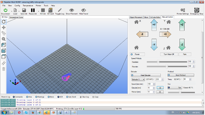
I connect the ISP (5V, GND, SCK, MISO, and MOSI) from the arduino to the hallo arduino board. Once ISP pins are connected plugged arduino UNO
board to computer and "Tools->Board" in the Arduino IDE an pick hallo.arduino, Atmega328p,9V,8Mhz internal occilator board.And then
"Tools->programmer and on appropriate port" in the Arduino. In my case I chose programmer Arduino as ISP. Beacuse I was using arduino
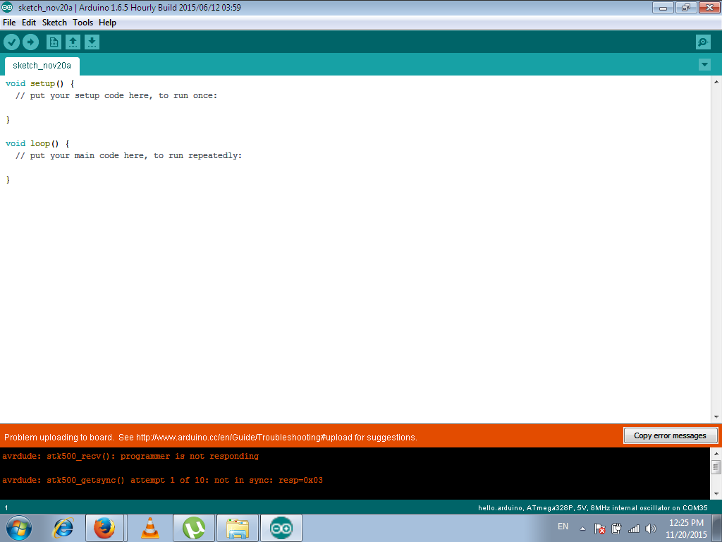
board to burn bootloader. Thats all then clicked on Burn bootloader. But it gives following error.


>Board>hallo.arduino,ATmega328p,5V,8MHz,ocillatorI got the following error saying that bootloader tool is missing.
>port>Arduino UNO (COM36) (This is on my computor)
>programmer> Arduino as ISP
>Burn bootloader


 |
 |
 |
 |
 |
 |
 |
 |