|
In this week assignment, I have to design input device. That has sensor and have to measure somthing.
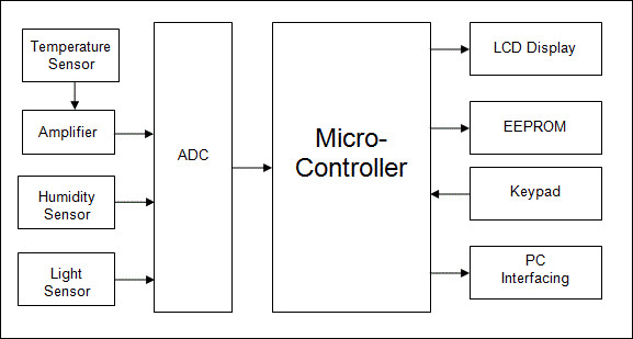
It can give input to the board to do any task I designed a board using Attiny44 that has input signls
from sensor. searching on internet I seen below diagram that gave idea about sensor input to microcontrollers
I decided to try out light intensity input device. This is because until I havent made any steble and long lasting
light sensor circuit using trough hole. It become bulky too. I started with designing a circuit board with a ATTINY44
So my input device had been working on input signal from light sensor. So i design my own board.
followed procedure
Design a circuit board
Mill the circuit board
Read out the board
Programming
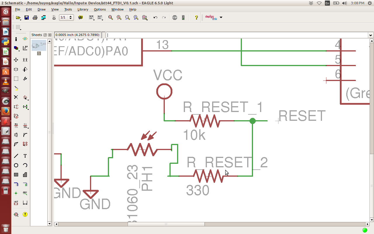
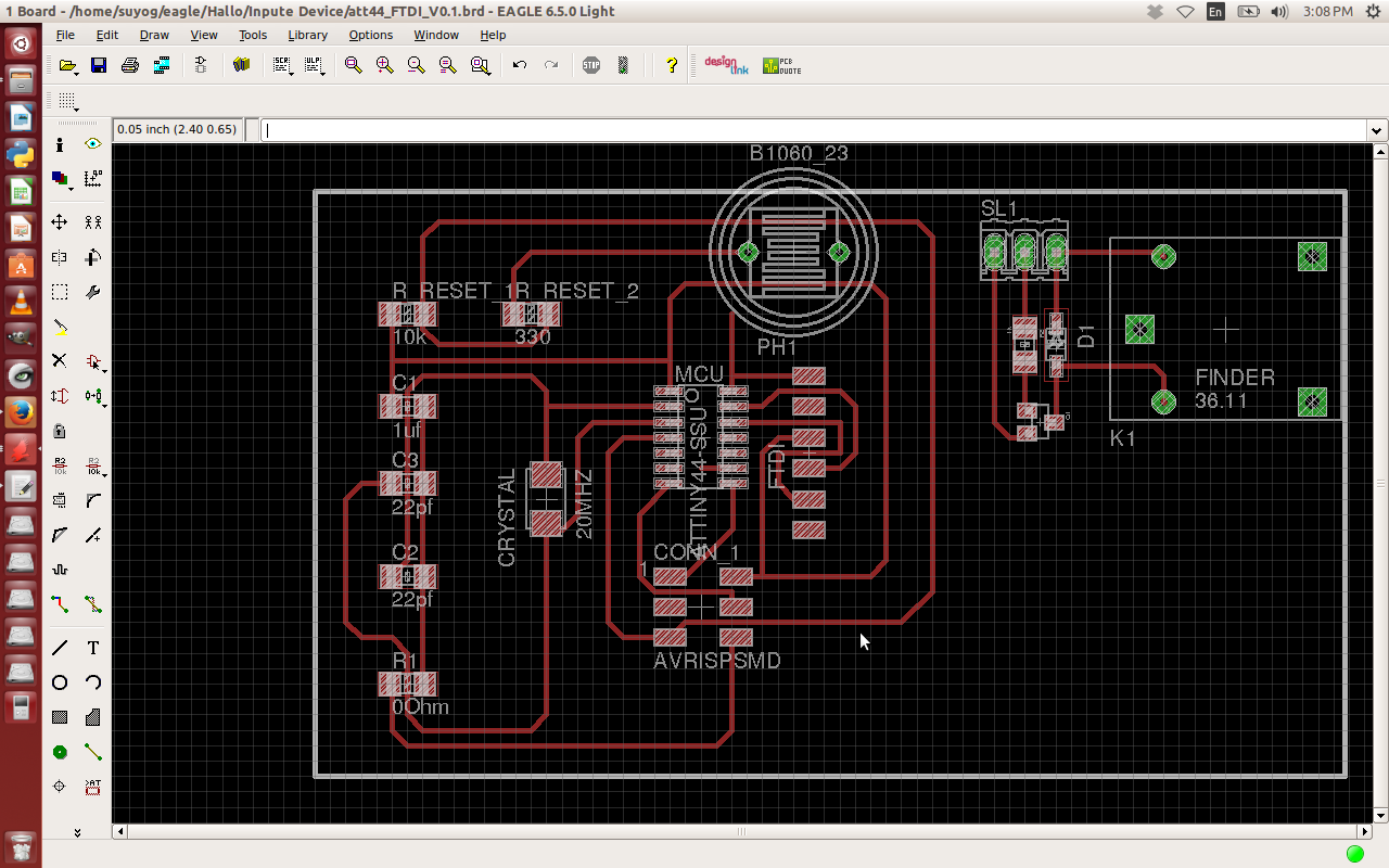
Desiged Board in EAGLE
I used Eagle again to design the board and I added the components. However, first I took some wrong pin headers, instead
of using the SMD 2x3 header I used the 6pin through-hole header. The same for the 4pins header so I needed to change this
after placing the right components I designed the board layout.I made some changes in Hallo_world board. It was only design
changes. And I put light sensor instead of reset button
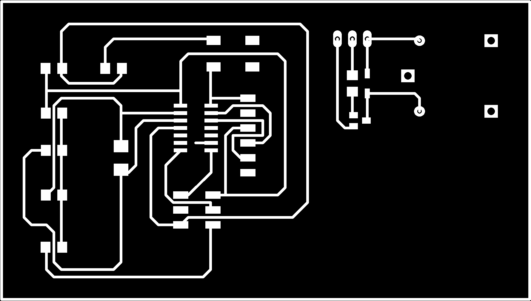
Milled traces On modela
After designing the circuit board I was almost good to go for the milling process. This process is familiar to me and again I
used the 1/64 for the traces and the 1/32 milling bit for the cutting out of the board. Following the milling process I soldered
the components on the board and proud to say I was able to solder the ATTINY44 in the right position the first try
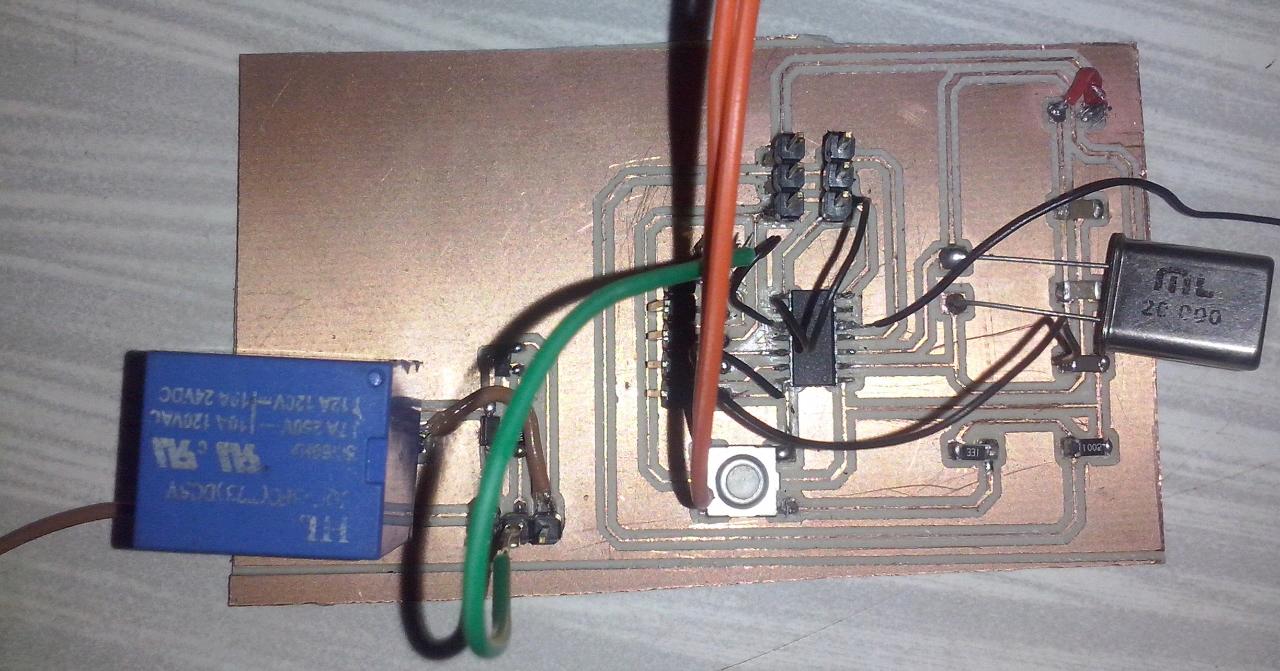
Fabricate the board
I made mistek there in exitment I forgot to connect output board by traces in circuit. Just design an imidiately sweech to board
while soldering componants came to know about that misteks.also I came to know that pins are get shorted in circuit To prevent
pins from incurring signal jump during programming, make sure PCB circuit boards where programming pins are located is not connected
with other circuits.
Read out board
read out the Datasheet to know about port pins for input and output.
Programming
As Im using Light sensor as input signal. So while programming I need to define Input pin and output pin. Set the condition for
required pins . Hear I set LDR at reset pin and supply pin.Now resistance changes as light falls on it. When resistance decreases
then this become reset condition. Supply will get connect to the reset pin to attiny44. Due to this all port pins pull down to zero.
That means processor get input and it gives some output.
Download Eagle files
Programming
I installed arduino IDE for programming. But during installation i faced lots of problem. I was able to upload the basic blink sketch
earlier, but now that fails as well. Yes I have verified I am selecting the correct COM port and board and am using the most recent
version of the application. But I did not get what went wrong there. But stoped all delet installed version and again followe the inst
llation process from start to end. Its my frustrated step of problem solving everytime i followed when get frustrat. But it works somtimes
It happens to me this time it works.
Now need to program microcontroller. As I had programmed Hello world in week ago. This time I felt exited for programming. So
I followed
Embedded Programming assignment to write program and upload it on microcontroller sucessfully. I did many mistakes during.
I wrote program and i got error for such simple program of led blinking. It hapaned many times. I had checked many times but I did not
get Why do I get an error? Then i left from there just get relax and came back after some times spending outside. Just review program.
So there suddenly I find mistek that i did not declaired variable to int led=10 onec it placed my proram get compiled immidiatly
int led = 10;

// the setup routine runs once when you press reset:

void setup() {

  // initialize the digital pin as an output.

  pinMode(PA3, OUTPUT);

}

// the loop routine runs over and over again forever:

void loop() {

  digitalWrite(PA3, HIGH);

  // Port A P3 is High (HIGH is the voltage level)


 }
I burnt down the above program in attiny44 successfully using arduno board
Download Programming Code
I was feeling proud on me and start encourging myself by furthet using another sensor. But I realized still need more practice. I tried
with IR sensor but it wasnt work. But it doesnt matters to me i decided to work on it sucessfully
|