Goal
For this week I wanted to create an LED status display for my final project. I am going to start with 5 LEDs with a view to expanding to significantly more going forward. For purposes of expandability, I am going to use 74HC595 shift registers.
My reasoning for using shift registers over additional µController devices is twofold, the first is cost, based on DigiKey prices in quantity a 74 series shift register will cost approximately $0.12 per unit, an ATTiny44 in quantity will cost around $0.70. My second reason is reliability and simplicity, I have found the 74HC595 to be a monsterously tolerant device to many sorts of electronic abuse, I have infact induced one to self-desolder through incorrect wiring, reconnected it (correctly) and had it perform perfectly.
Design
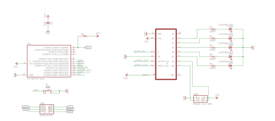
I designed the board in Eagle based around the ATTiny44 µController, ultimately I will be using a ATMega328P or potentially a SAM3X (WooHoo 32 bits baby!) but for this prototype I don't need the grunt of the larger chip.
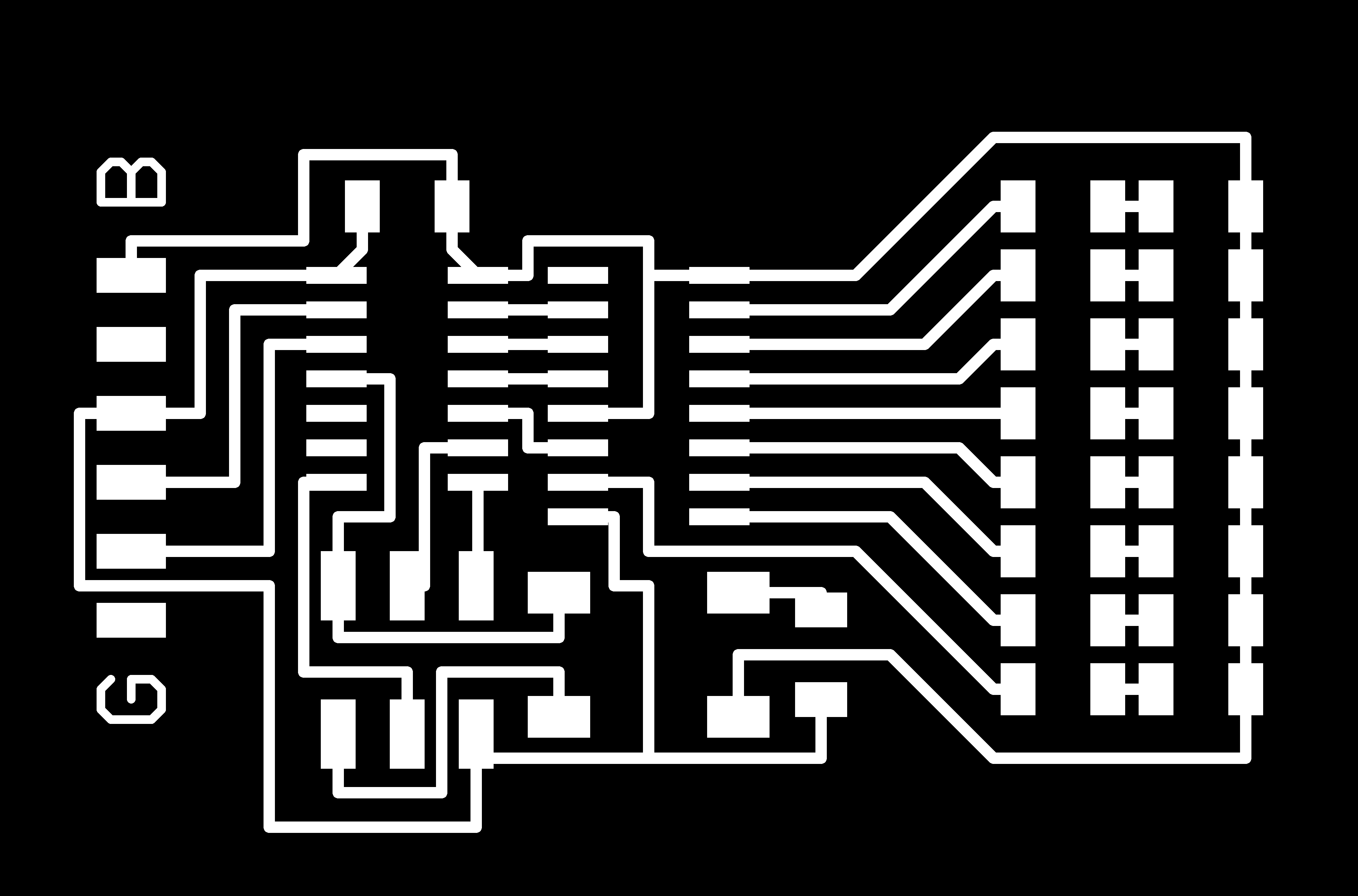
Version 1
 Version 1 had a slight issue, namely that I had installed the shift register backwards, as a result I managed to heat the poor little thing up to a point where it partially desoldered itself. Unfortunately, I had not taken note of the glassy state of the solder joints when I sought to check the components with an organic digital thermometer, this hurt. But hey, why waste an excellent opportunity to improve the board layout? Onwards to Version 2!
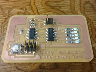
Version 2
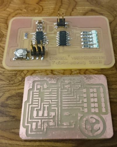
In the world of modern electronics, smaller is better! So behold a smaller, sleeker version of the shift register board!
The first obvious difference is the lack of an external resonator, given that this board is for experimentation only I had no need of the additional clock speed having and external source would provide so I have simply reverted to using the built in resonator at 8MHz, this saves on space and on parts.
Version 3
Ok, I can hear you thinking it, "Version 3!?!?! Of a simple output multiplexing board!", and I understand, it's ridiculous. The reason Version 2 didn't work had nothing to do with the Version 2 board itself, it had to do with an overly tired me and a misbehaving AVR ISP Mk II.
It was a dark and stormy Friday night in Wellington and Craig and I were working on a set of reference boards for our networking week, then it came time to program them.
exclaimed avrdude, on all 3 boards. Surely we could not have screwed up all 3 of these dead simple boards! After much fretting we decided we should at least test with the spare AVR ISP MkII programmer. It worked. By our calculations we have collectively wasted the better part of a day trying to chase down errors on our boards that didn't exist all because we assumed the AVR ISP Mk II was more or less bulletproof. Lesson Learned.
Programming
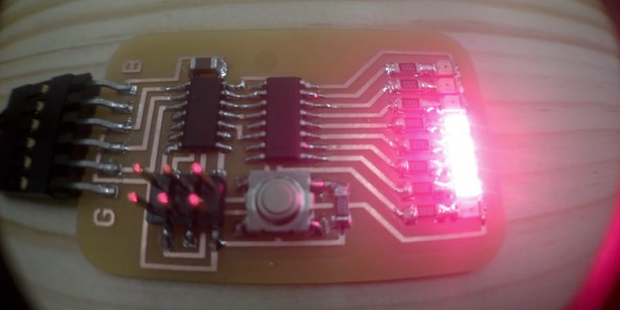
For testing I have just made a simple sketch to sequentially blink the LEDs on the board using the Arduino shiftOut function. More to come here once I have a working board.
The attached program will allow you send an integer to the board over serial and have it displayed in binary on the 8 LEDs attached to the shift register.