Introduction:
Third assignment is making fabISP programmer,ISP is the In System Programming
First step is installing FabModule.download the Fab_src.zip from
Open Terminal --> type following command for downloading dependencies.
sudo apt-get install python python-wxgtk2.8 python-dev python-pip gcc g++ libpng12-dev make bash
okular libboost-thread-dev libboost-system-dev cmake
Go to Desktop using change directory command
cd ~/Desktop
Then make directory fabmodule
mkdir fabmodules
Download the fab_src.zip from--> wget http://kokompe.cba.mit.edu/fab_src.zip
wget http://kokompe.cba.mit.edu/fab_src.zip
Unzip the fab_src.zip in the fabmodule directory
unzip fab_src.zip
Type next command on terminal --> make fab
make fab
To open fab module tyoe command fab
fab
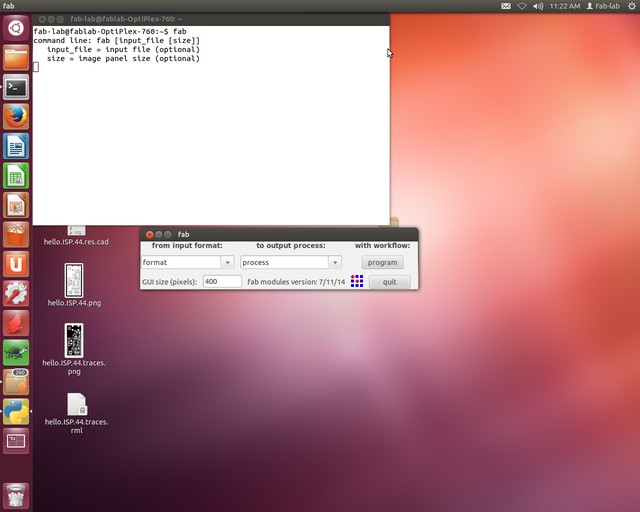
After executing fab command on the terminal following window will pop up.which will ask the format of the imported file. about PCB milling it can be .cad file or .png file with resolution 500dpi and the process to be done on imported file.here it is .rml (Readline Markup Language) last process is converting make_png_rml this converts imported image to the .rml format, which is machine (Roland Modela) acceptable format. figure 1 shows the screenshot
Figure.1
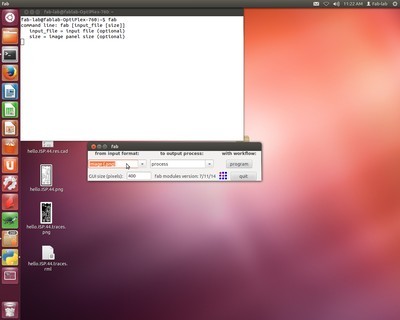
Following Figure 2. shows the input file to the fab module here we are importing Hello.ISP.44.Traces.png with resolution 500dpi, Following figure shows the setting
Figure.2
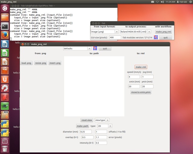
Next is selecting the output format for PCb milling on modela machine acceptable format is .rml(Readline Markup Language). Figure 3. shows the output format
Figure.3
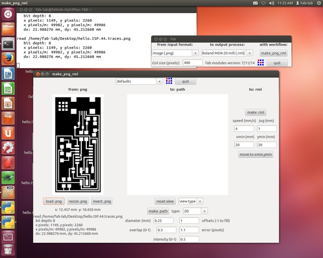
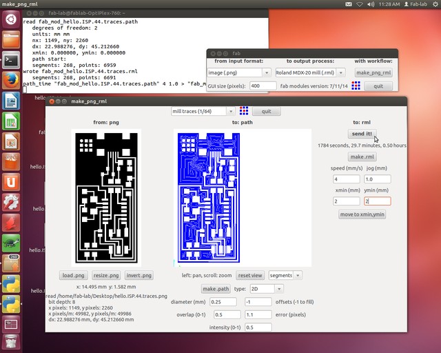
Now select the option Make_png_rml-->After clicking on the make_png_rml following window will pop up is divided into three secctions 1)from png 2)to path 3)to rml first section from png is asking to import actual .png file from the desktop.load .png file black & white --> Figure 4 shows the imported image
Figure.4
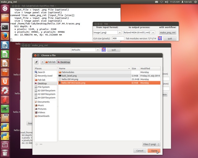
At section 1)from png import or Load .png file from desktop,Refer figure 5
Figure.5
After importing file is loaded in .png form black and white image, black is unwanted part and white is the tracks.exctly below the .png image it shows the x and y cordinate,path of file import then resolution in pixels.refer figure 6
Figure.6
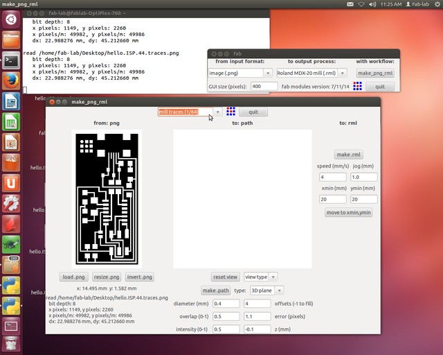
Section to .rml here we need to set milling bit which we are using for PCB milling it is 1/64 bit,Figure 7 shows the setting
Figure.7
Next click on the path botton which will create the toolpath
1) segment
2) segment+direction
3) segment+direction+connection
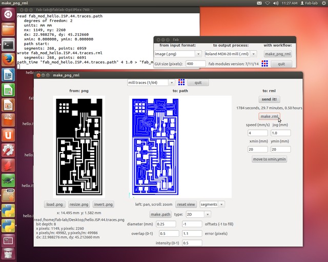
I am selecting with segment and plane= 2D and offset=-1 here it will generate infinite contours if it is offsets=1 then it will generate 1 outer line around the tracks.Figure 8 shows the setting for contour.
Figure.8
In section three --> to rml, here click on the make rml this will convert the traces of png image into the .rml format.can be sent to the modela machine,Figure 9 shows the conversion process
Figure.9
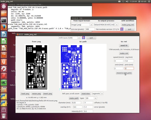
change the x and y cordinate according to the board setup on modela bed
Figure.10
Finally click on the send to machine.refer figure 11.
Figure.11
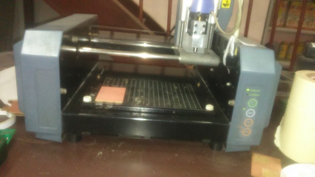
Now we will set the copper plate with two way stick tape at cordinate(0,0) i.e. x=0,y=0;
Figure.12
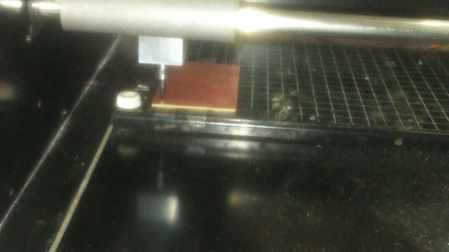
Press view then down button on the modela till it touch the copper surface,Penetrate the bit little into the copper plate.This is machine x,y,and z zero.
Figure.13
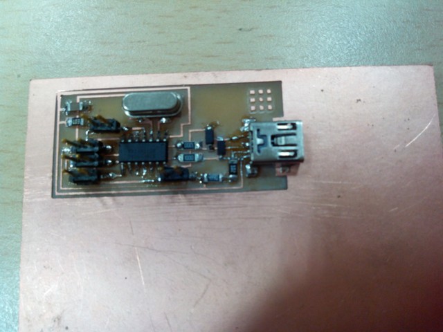
fabISP pcb is ready but I forgot that i also need to cut the board, While setting the modela I didnt use underneath copper board. I cut the board using Scroll saw. then soldered with weller soldering gun it really need very fine soldering tip to solder SMD packages espacially when soldering USB bcz finally i got board very thin pad and it was difficult to solder
Figure.14
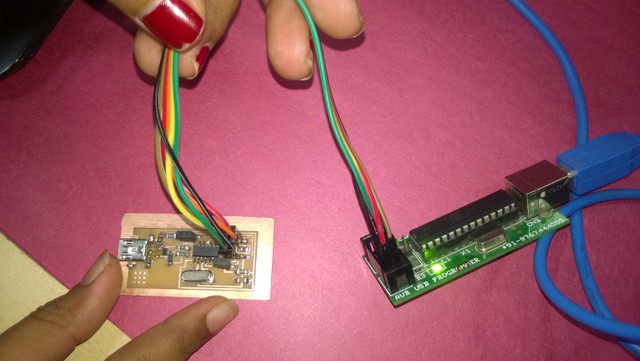
Successully done the soldering checked continuty,Now programming the ISP need 6 pin cable and other AVR programmer so my fabISP becomes the target device following Figure.14 shows the connection,fabISP has 6 pin 1)MISO 2)MOSI 3)SCK 4)RST 5)GND 6)VCC connect this pin properly to the other programmer here i am using AVR USBasp programmer to program my fabISP.
Figure.14
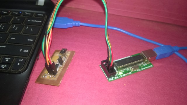
From programmer connect USB to laptop to program ISP through other programmer in following Figure.15 Blue USB cable connected to Laptop,JS1 is used for jumber before programing the board very important is closing connection with jumper.
Figure.15
Figure.16
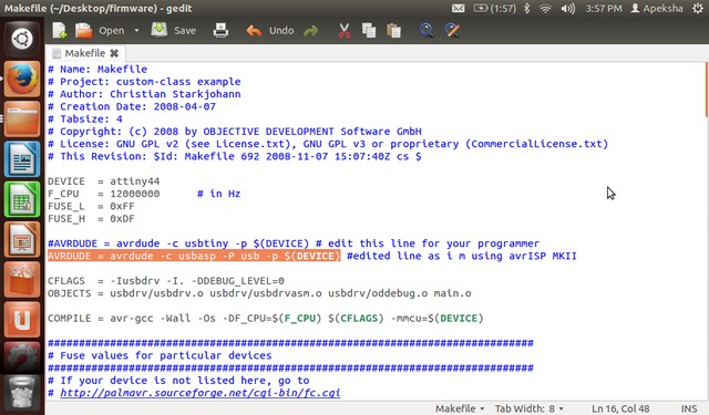
Insatlled avrDUDE ,avr-gcc and other required packages as given in the tutorial.Open make file search avrdude -c usbtiny -p $(DEVICE) NOTE: add # infront of this line and add highlighted text command in the make file(check your programmer make).
Figure.17
Open terminal with short cut key Ctrl+Alt+T or click on terminal icon for programming
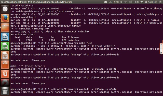
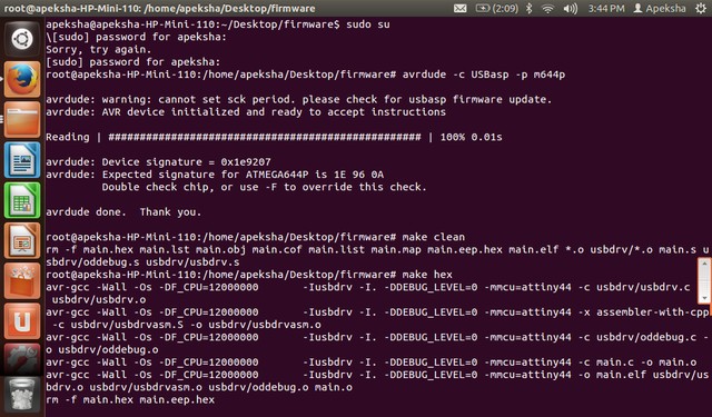
to check connection with the programmer i used following code.initially it was connection problem Here user need to have administrative privileges using sudo su go to the desktop ans firmware.cd Desktop/firmware this will ask authenticate password.and then following code will work
avrdude -c usbasp -pm644p
Figure.18
Figure.18 shows error message to program the faISP board,Do sudo su-->System password.
then use following code to detect device and make clean
avrdude -c usbasp -pm644p
make clean
make hex
Figure.19
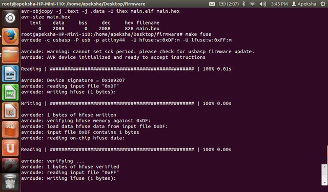
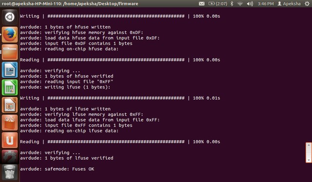
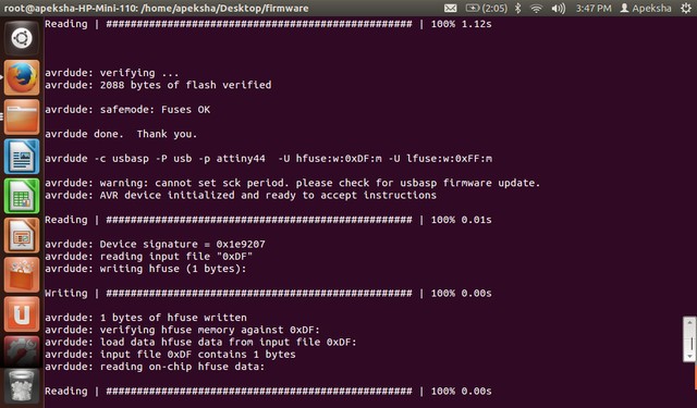
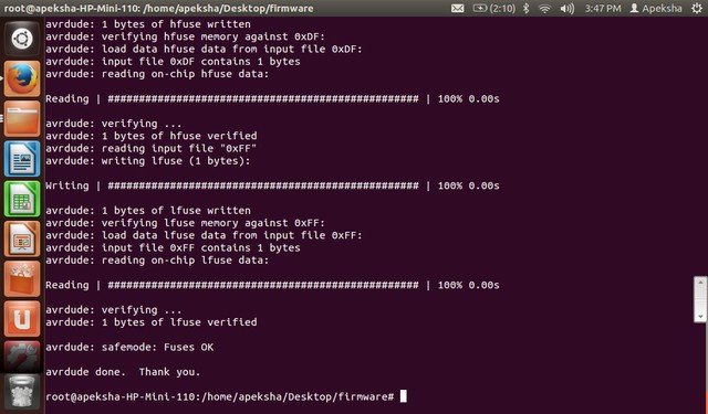
make fuse
Figure.20
Figure.21
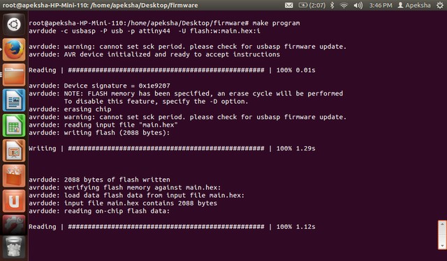
Then last command is make program
type make program
Figure.22
Figure.23
Figure.24
Succesfully completed the fabISP programmer.
.png file
outline file
