The board contains:
3 push buttons (incrementing, decrementing, and roll)
Incrementing: Increases the turning time of the DC motor to suspend a longer part of the tape.
Decrementing: Decreases the turning time of the DC motor for suspention.
Roll: Is the order given to turn the motor.
5 LEDS (indicating how long will the suspention be according to the adjustments using the incrementing and decrementing buttons)
The DC motor that does all the work
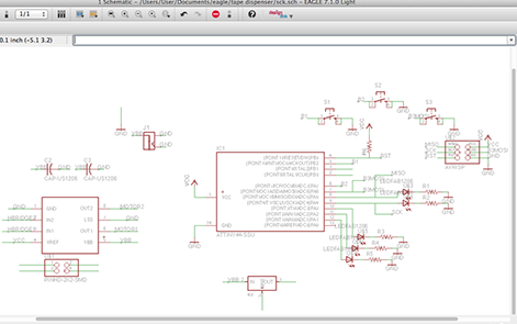
Using Eagle
It is always the hardest part, to start! From where to start? this is usually the common question.
So, I started with dropping all the needed components into the Eagle software canvas. Now connect the small parts together such as the LEDs and Resistors, push buttons, capacitors. And then Connect these small units to teh BRAIN (IC).
The last step on this first step of the final project controlling board is to double check all the connections and make sure some college also takes a look at it before you get indulged in the next step, the PUZZLE.
Here are all the components I need:
1- DC Motor (geared)
2- 5 LEDs
3- 5 Resistors
4990
4- AT Tiny 44
6- Resistor 10K
7- 3 Capacitors (1uf/0.1uf/10uf)
8- 3 push buttons
9-Voltage regulator
10- Power J (connector)
11-
Motor connector
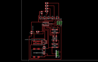
Using Eagle
Honestly this is my favorite part - The puzzle
I have made a lot of attempts to make a circuit design that suits the functionality of the components and to solve the puzzle of connection between teh components.
Some of the points I kept in mind are:
 |
 |
Using Eagle
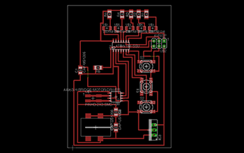
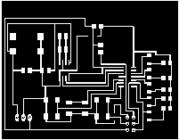
Using the option of (layer selection) on eagle software when exporting the image of circuit trace, I have been able to export two different tracing images, one for the surfacemount componemts (Figure A), and the other one (Figure B) for the through hole components along with the outter cut.
Why did I use this layer selection option?
To know exactly where are the through hole components are located without the trace and export without any shifts of the components in relation to the trace.
After exporting Figure B, I inverted the colors for the modela to associate the black color as mill.
 |
|
| Figure A | Figure B |
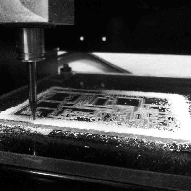
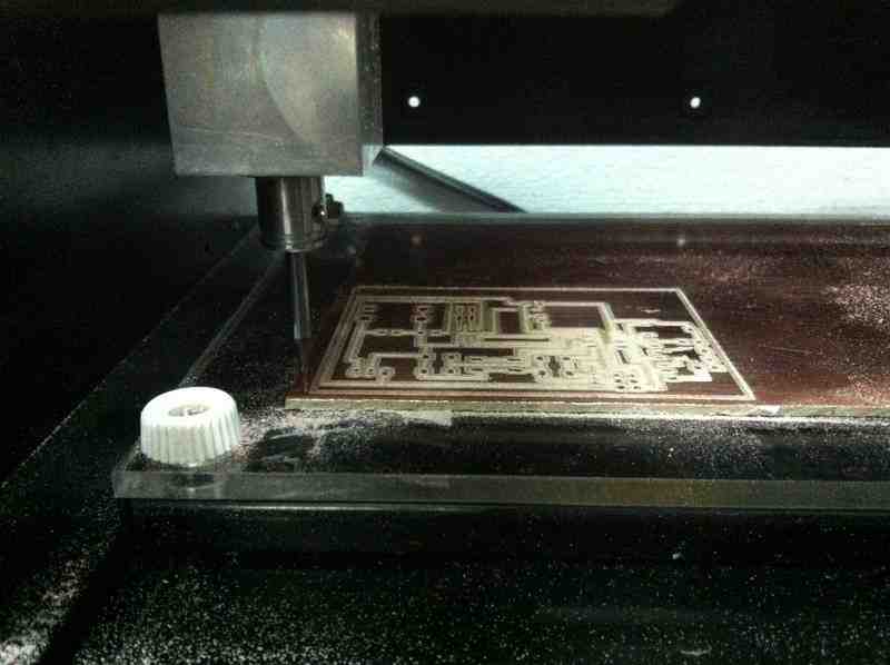
Using Modela
For this board I used a 1/64 inch diameter end mill for tracing since the board is moderate in size and the traces are fairly apart from each others to let the end mill work through neatly without damaging the circuit traces.
STEPS:
1- Open the software (Fab Modules), set it on the output format Modela RML and the input format png
2- Insert the interior trace, using the 1/64 inch diameter end mill to mill the electrical traces
3- Fix the board using super glue, or double sided tape
4- Prepare the machine, zero the X, Y, and Z axis, and start milling
5- When the trace is done, insert the outer trace to cut the traced circuit from the excess material, using the 1/32 inch diameter end mill
6- Finally, prepare workbench and components
 |
 |
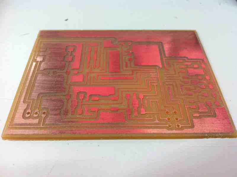
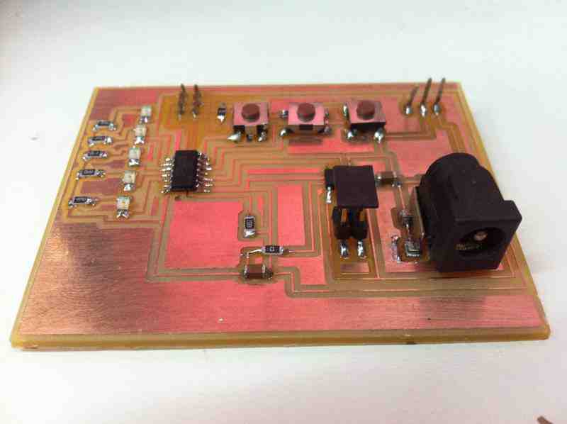
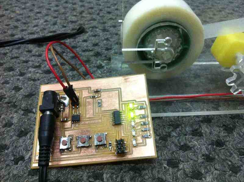
While designing the circuit i kept in mind the position of LEDs, push buttons, and jacks to be user friendly as much as possible. As you can see in the components picture below, the LEDS on the left side of the board are all associated with their resistors;
The IC is somehow in the middle of the board;
The 3 push buttons at the top edge to be accessed easily;
The voltage regulator is on the top right side of the board;
The jack is located at the bottom right side of the board to be accessed easily and away from the push buttons and LED for good sight.
N.B: The LEDs here are indicators of the incrementation and decrementation commands given by two of the three push buttons, and the third push button is to turn the motor to bring out the tape.
 |
 |
The board contains:
3 push buttons (incrementing, decrementing, and roll)
Incrementing: Increases the turning time of the DC motor to suspend a longer part of the tape.
Decrementing: Decreases the turning time of the DC motor for suspension.
Roll: Is the order given to turn the motor.
5 LEDS (indicating how long will the suspention be according to the adjustments using the incrementing and decrementing buttons)
The DC motor that does all the work
Using arduino software
Before starting the programming with the help of some colleges at Fab Lab Egypt, I wrote a flow chart in order to know all the functions of the board and to put a command to each condition. The flow chart helped in the process of coding.
#define inc_button 6
#define dec_button 8
#define start_button 7
#define motorA 9
#define motorB 10
const int leds [] = {1, 2, 3, 4, 5};
const int ledpincount = 6;
int counter = 0;
bool flip = false;
void loopled (){
for(int i = 0; i < ledpincount; i++){
digitalWrite(leds[i],HIGH);
delay (300);
}
for(int i = 0; i < ledpincount; i++){
digitalWrite(leds[i],LOW);
delay (300);
}
}
void setup()
{
for(int i = 0; i < ledpincount; i++){
pinMode(leds[i],OUTPUT);
}
pinMode (motorA,OUTPUT);
pinMode (motorB,OUTPUT);
pinMode (inc_button,INPUT_PULLUP);
pinMode (dec_button,INPUT_PULLUP);
pinMode (start_button,INPUT_PULLUP);
loopled();
}
void loop (){
delay(200);
if(digitalRead(inc_button) == 0)
{
for (int k=0; k<=counter; k++){
digitalWrite(k+1, HIGH);
}
counter++;
if(counter>5){counter=0;}
}
if (counter==0)
{
for (int k=1; k<=5;k++){
digitalWrite(k, LOW);
}
}
if(digitalRead(dec_button) == 0)
{
digitalWrite(counter, LOW);
counter--;
if(counter < 0){counter = 0;}
}
if(digitalRead(start_button) == 0){
motorincrement();
}
}
void motorincrement()
{
digitalWrite (motorA,HIGH);
digitalWrite (motorB,LOW);
delay (counter*1000);
digitalWrite (motorA,LOW);
digitalWrite (motorB,LOW);
}
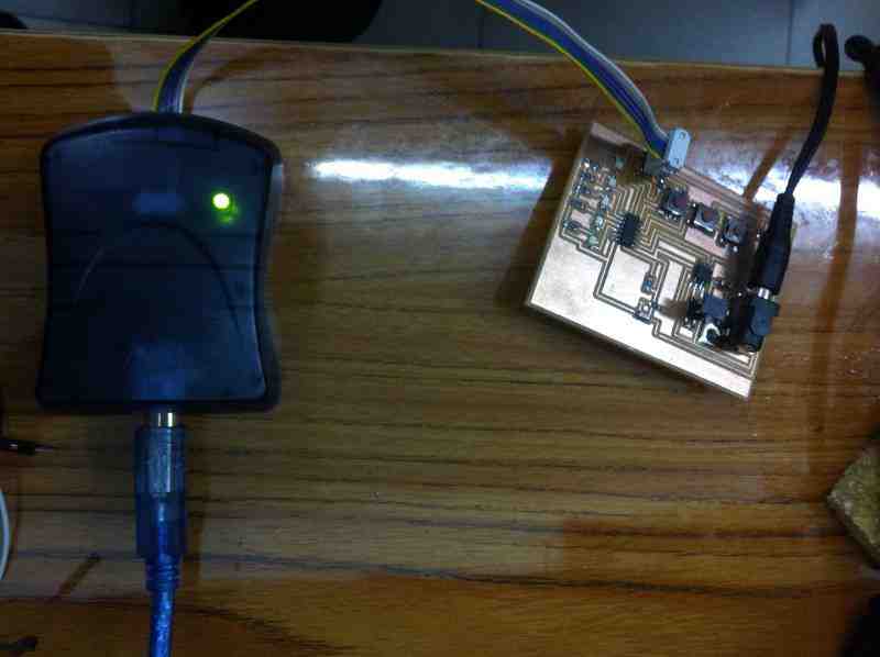
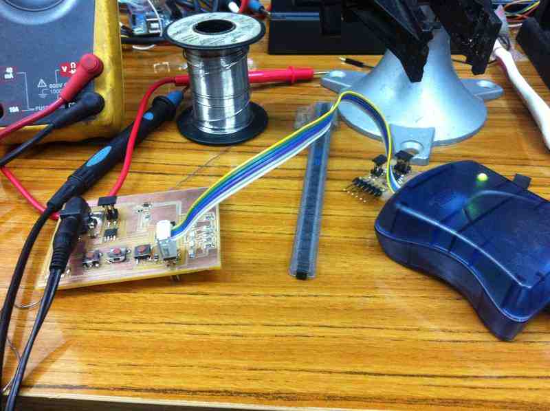
After burning the bootloader and uploading the code to the board, here is what happens xD
The 3 push button, the 5 LEDs, and the motor work properly and function well.
 |
 |
 mariamwaelgado@gmail.com mariamwaelgado@gmail.com |
 http://mariamwaelgado.wix.com/ http://mariamwaelgado.wix.com/mariam-wael |