
Mechanical Design / Machine Design
The goal of this week assignment is to create a mechanical design for my final project.
Requirements
The only mechanical part of my project is the pan-tilt mechanism controlling the eyeball up-down movement and the body rotation inside the vase.
In order to work properly for my project this mechanism has also to fit my existing concept design for the cactus-shaped case and coexist with all the other electronic parts that must fit in there.
The eyeball itself must contain a USB camera and a way for it to stay centered and not cover the lens viewing area.
The vase should allow for additional space for containing the pan mechanism and all the wires connecting the electronics to sensors on the top.
Finally all the design should be cheap to build, easily assembled and disassembled, with the goal of being 3d printed in several parts to reduce chances of long prints messing up.
Work plan
Even if it looked simple at first the design of the whole object resulted quite complex for my modeling skills. So I decided to split the task in several modules and approach each one separately.
I started with a paper sketch of the case, to make things more clear in my mind:
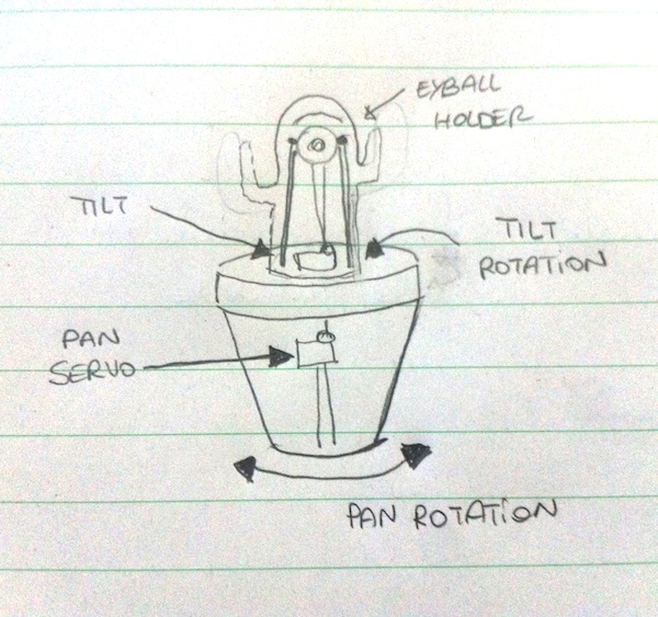
Using this drawing I could identify some main parts for the design:
- vase with pan servo motor holder, allowing space for cables
- rotating base attaching to the pan servo motor and holding the pan motor
- holding structure for the eyeball (but also mouth display, ultrasonic, leds and so on)
- eyeball
- tilt mechanism
- external "cactus" case
Additionally to make the model fit all the electronic parts, I needed to measure and model them too to test the design before building the actual parts.
Modeling
Electronic components
I first started to model all the electronic parts, measuring them with a caliper in order to replicate the exact dimensions:
 Raspberry Camera
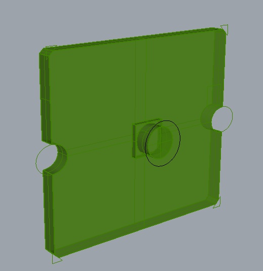 Microsoft USB Camera
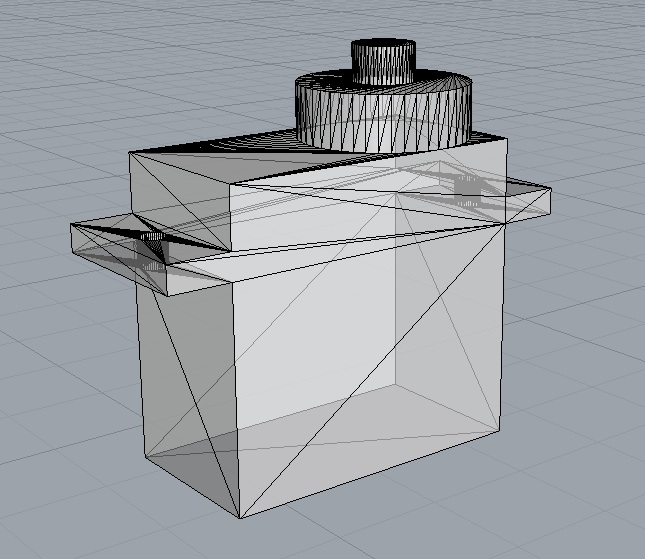 HS-55 Micro Servo
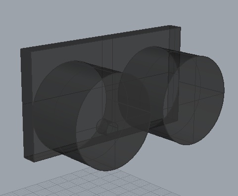 Ultrasonic Sensor
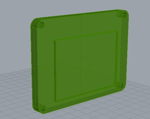 OLED Screen
Finally I could start the actual modeling for my project. The following parts were modeled:
Eyeball and tilt-mechanism
The eyeball design is probably the most difficult part of the overall project. In fact it has been changed several times during the various iterations. The main problem with it is that it dependant on the size of the camera. Early in the project, when I didn't plan to use the Raspberry as a host controller I expected to use a serial camera for the project. Later I moved to the RaspberryPI camera, but having found it cumbersome to be supported by the Linux software and also more expensive than a standard USB camera, I followed Neil advice and adopted the latter.
Each camera is different, and it is quite difficult to know the exact dimensions for each without tearing them apart to discover electronics.
The basic tilt mechanism I imagined worked by using a rigid part attached to a microservo motor on the rotating base, which would pull and push the top of the eyeball in an horizontal motion.
Building a test eyeball and support structure proven this choice to be difficult to implement, as while rotating the eyeball was also moving vertically, requiring a more flexible part for pulling it.
After some iterations I managed to put together a mechanism based on a nylon string (using a fishing line) and redesigned the eyeball so it was pulled from the top and the bottom. The fishing line is held in the middle of the eyeball by a support attached to the holding structure.
The first version of the eyeball:
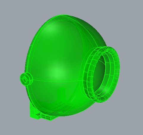
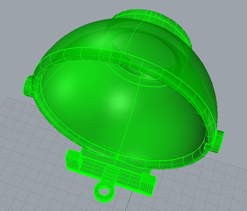
The second and final version:
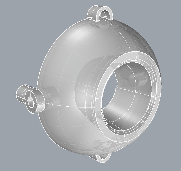
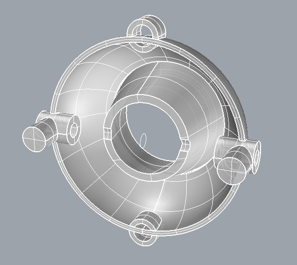
The second design also provides support for the camera thanks to two fittings and a backplate holding everything together using a press fit mechanism (maybe helped by some heat applied to seal the plastic)
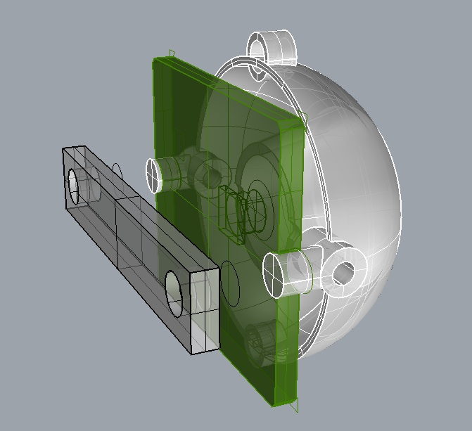
The holding structure allows to attach both the eyeball on the top, and the display and ultrasonic sensor in the lower part, leaving space for cables in the back.

Update 7/06/2014
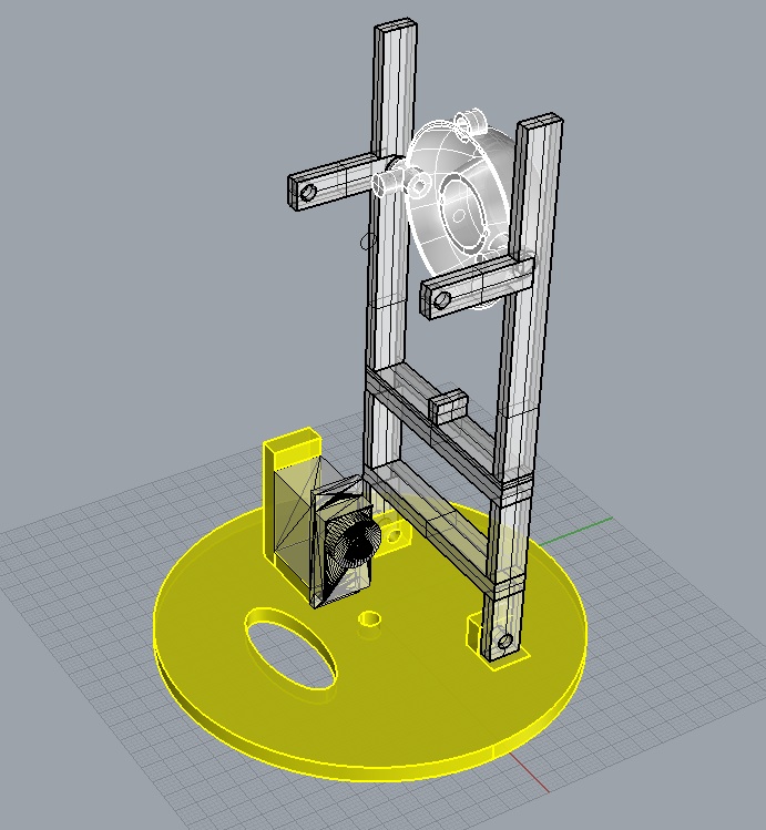
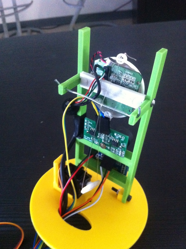
This is how the built tilt mechanism looks:
Rotating base
The rotating base pictured above must allow to fit the structure holding the eyeball and other electronic parts. These could have some weight so the fitting on the base should support the structure and must be solid enough not to move while rotating the body.
I did two iterations for the rotating base, to accomodate changes in the tilt mechanism as discussed in the next sections.
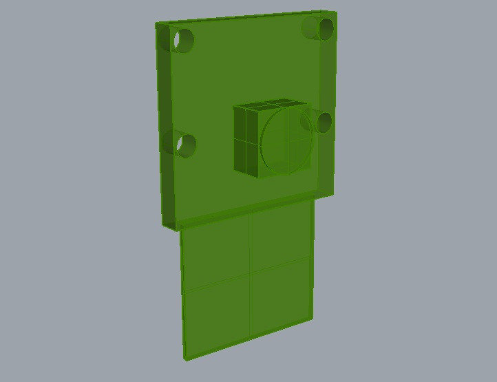
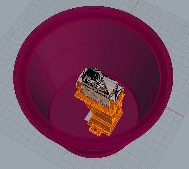
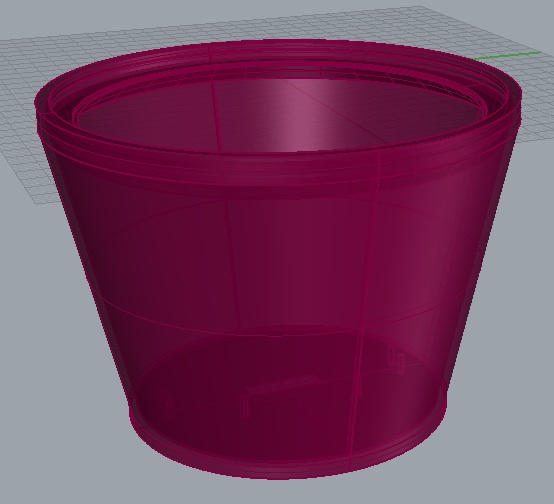
Vase and Pan mechanism
The pan mechanism is based on a servo motor providing 180 degrees rotation of the cactus inside the base. This attaches to a plate which is allowed to rotate at the top of the vase.
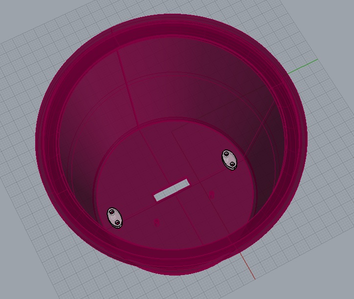
The pan mechanism is attached to the vase with two screws. The servo mount in meant to be positioned in a way that allows the servo wheel to be at the center, still leaving space to cables.
I also designed two small clamps to allow securing cables to the bottom of the vase. The hole in the bottom allows to guide the cables down to the controller boards.
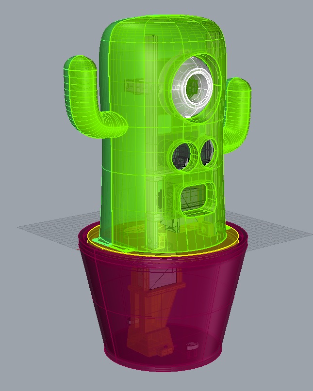
Case design
Finally I rebuilt the cactus shape making space to fit all external components, making sure components would fit as tightly as possible in the case.
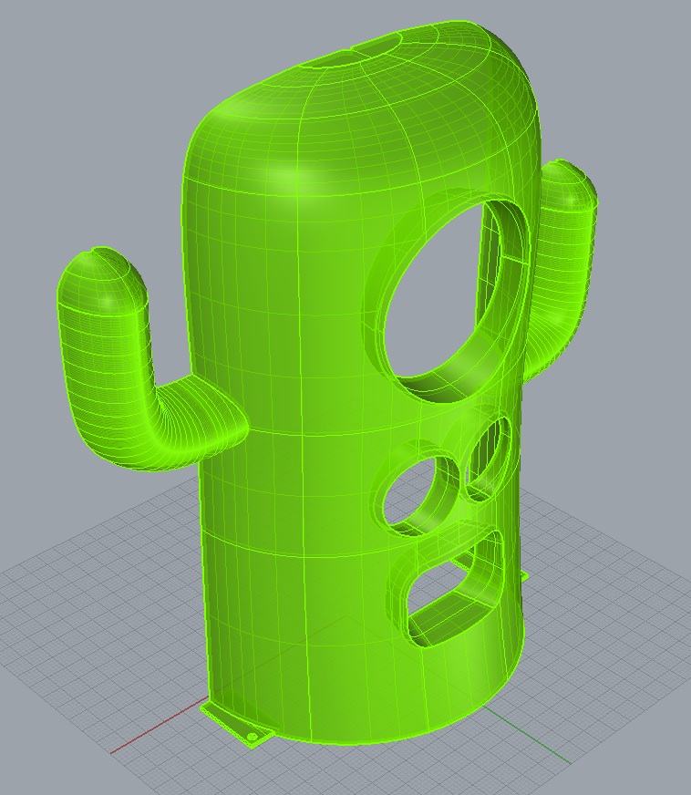
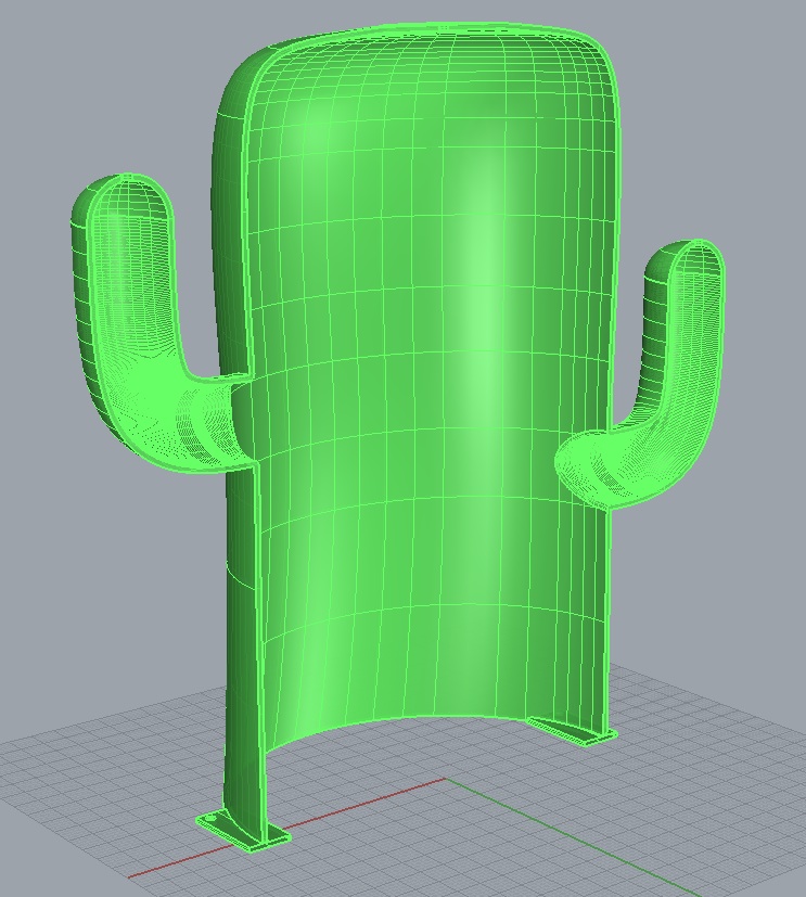
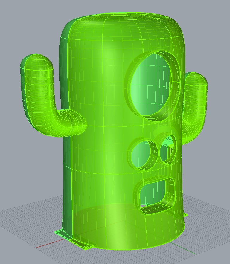
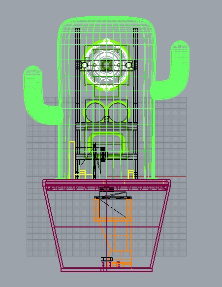
Finished design
I'm very satisfied of the final design. Having all the parts already assembled in the 3D models made me more confident that the design could work, and will speed up the actual building of the model out of the 3D printed parts and electronics. This was also my first time designing something with so many parts aimed to live outside a monitor!
Rhino 3D Files
- Model
- Electronic Parts: Oled, Servo, Raspberry Camera, Ultrasonic Sensor, MS USB Camera
