
Principles and practices, project management
interface and application programming
mechanical design, machine design
LED + BUTTON Assignment:
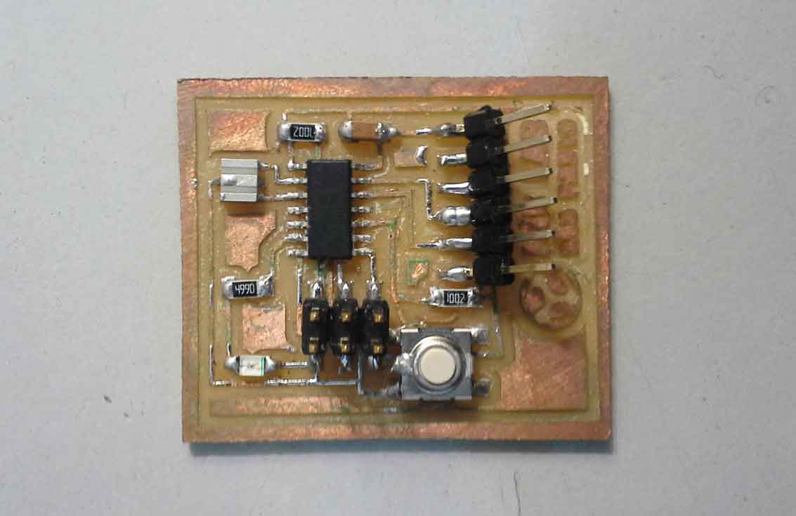
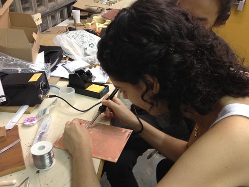
Update on soldering the board:
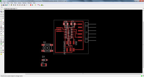
After I designed and printed the board I soldered all the components following the schematic board of the LED+Button board.
-----
After my first experience on dealing with electronics in the assignment #4, I had to go further in the subject and this week I had the task to design, print and assemble my first circuit board. I can tell that the experience was quite surprising, once I thought that dealing with electronics would be much more difficult than it´s been until now. To be able to design my first circuit I needed to download and install the software Eagle. This is an open source software that allowed me do add and combine component and paths along the board. The software was not difficult to use and had a simple interface. After installing the software I downloaded the library Fab.lbr from the assignment page. This library, comes with a set of components that are generally used in FabLab projects. I saved the library in the “Lbr” sub-folder inside Eagles folder. Once I opened Eagle I loaded the new library (Fab).
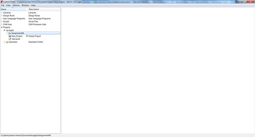
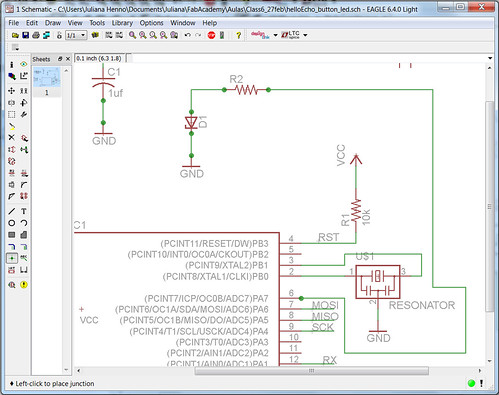
The circuit I wanted to do is an adaptation from the HelloEcho circuit board and I wanted to adapt it in order to add a button that would activate a LED light. I didn´t start from a blank page, instead of that I started to build my circuit over another file called: HelloEcho.sch / HelloEcho.brd. First I created a new subfolder inside of the Eagle project folder called “Assignment #6”. After that I placed the two files (helloecho.sch / helloecho.brd) in the Assignment #6 folder.
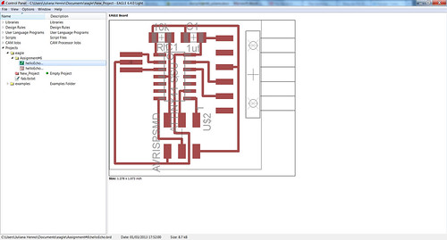
I started working with the schematic version related to the file helloecho.sch. So I had to create a copy of the file and rename it helloecho_button_led.sch, with automatically generated a file called helloecho_button_led.brd. Now that I have already renamed the file, I opened the library file “Fab.lbr” in order to load the components for the project. To add a component from a library is very easy, we just need to click on the icon “add” at the left side and search for the “Fab” folder that I previously opened/loaded.
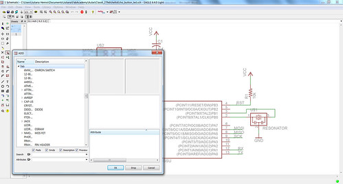
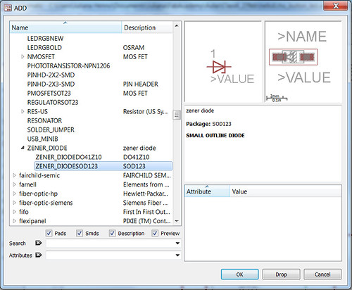
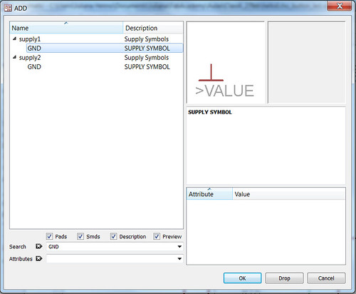
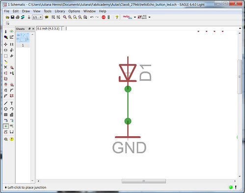
The components that I added were: switch (6MM_SWITCH6MM_SWITCH), zener diode (ZENER_DIODESOD123), resistor (RES-US1206FAB), ground (GND – supply 1)
Now that the components are already near the main circuit I started to build the connections between them in order to close the circuit to the function I previously decided. To create the conections/paths between the components I used the “wire” that is located at the left side of the program. To confirm the connection between the two components I used the command “junction” to reassure the connection by placing a green dot in each connection. The first connection is between the ground, the LED and the resistor. From the resistor I made a connection to the port 6.

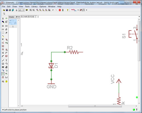
Now I created a connection between the ground, the switch and the voltage.
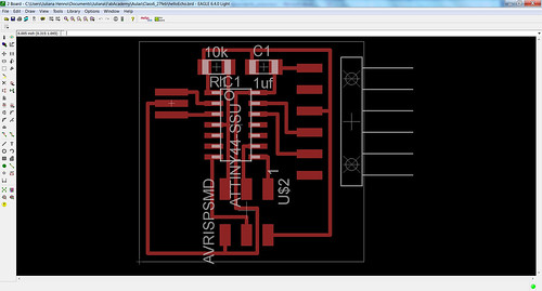
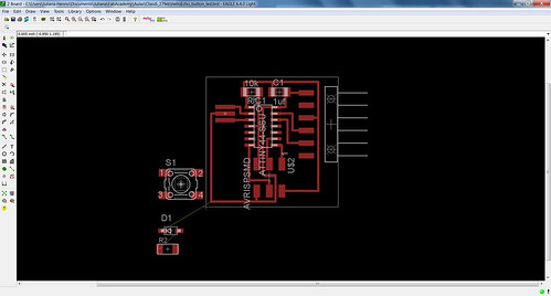
Back to the board view I could make some adjusts in the components position. When I opened the board view all the wires were mixed and needed to be rearranged.
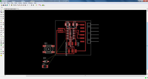
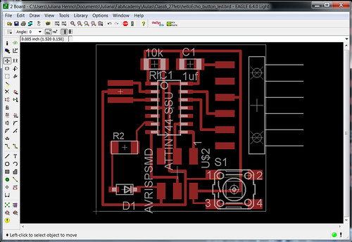
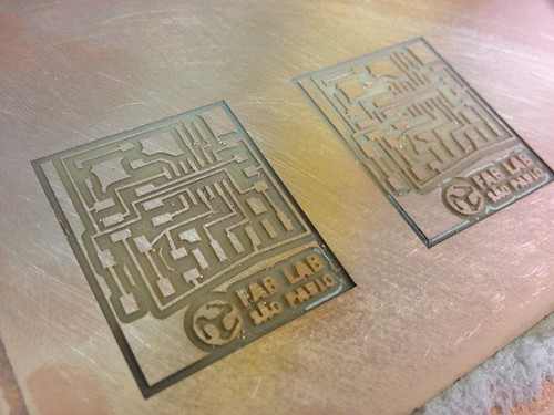
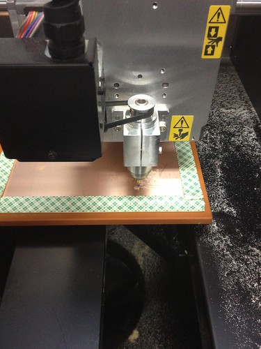
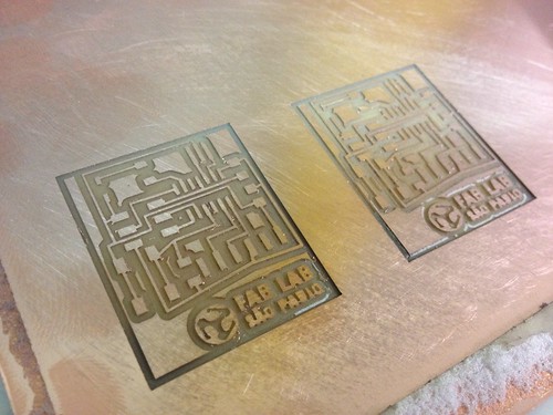
After I finish designing the circuit in Eagle, I exported the file of the board in a PNG file. In Adobe Photoshop I opened the PNG file of the board and added a 4mm margin to each side of the board. Also in Photoshop I added the Fab Lab Brasil logo to the circuit and created a secondary file, based on the first and erased the circuit letting only the board (in an inverse color). The two PNG files were ready to be printed. The first with the circuit to be milled and the second with the board to be cutted. We placed the board in the Modela and from FabModules we send the first file (with the circuit) to print.

Software: Eagle 6.4.0. / V Panel / Adobe Photoshop CS6
Hardware: Modela MDX-40A
Files: Eagle files