Assignment: plan and document a final project that integrates the range of units covered
Penta-Tones
My final project ideas took a lot of forms… I started with a QuadCopter, then I had some crazy plans of making a Nano-Sattelite (yep!!), then back to the copter, but I didn’t feel comfortable with any of them. I had to many open ends and I couldn’t figure out what parts I am going to design and make my self and what part I’m going to buy/take some ready made parts.
Then came the assignment of output devices, and connected me to some old loves of mine – Playing music and Playing games, and I decided I’m will make something that play instead of something that fly for my final project
Overview:
This project is done in collaboration with Ida Vass.
The project consist of five components that represent five different tones / sounds and one control component.
We split the work among us like this (it is not a very clear cut – but it lets every one of us to utilize as much processes and machines as possible): Ida is taking care of the end unit design and coding for the LED strips and Bend Sensor) and I design and programming the Controller unit (Design the box and programming the MIDI module and the RF network).
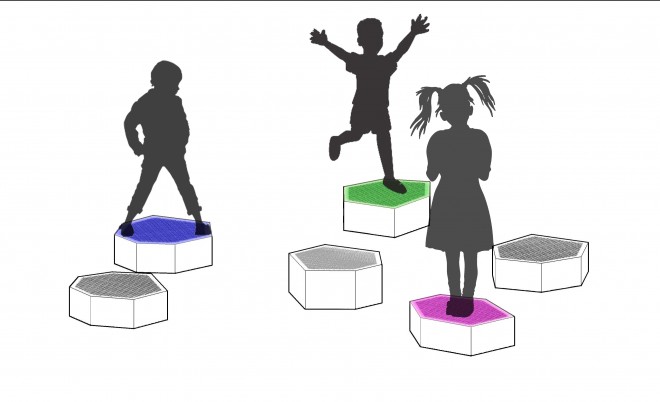
The components are placed on the floor. Stepping on a component will turn on its light and will send a message to the controler to play the right tone.
The components can be spread in a room or outside and be seperated from each other. Communication is done by using RF wireless communication.
The Penta-Tone will have two (out of the box) modes:
1. Playing (music) mode: as a component is stepped it generates light and sound.

2. Playing (game) mode: the controler will play random sequences of tones (each time an additional note will be played starting with one tone) and the players, will have to step on the right bubble to replicate the sequence.

Things that we are going to make (for sure):
- The physical stracture
- The step sensor + modules
- The control boards (Fabduino) – at least some of them
- If time allows: RF board
Processes that wil be used:
- CAD 3D Design
- ShopBot cutting and engraving
- Electronic boards design, milling & soldering
- Programming
Tasks that needs to be completed:
mmmmm… let see:
- We tested most of the electronic modules seperately (except for the step sensor – we still waiting for the materials to arrive…)
- We made some cutting and dukta technics on the ShopBot
So:
We need to complete the cutting tests and choose the right technic and parameters.
We need to make the step sensor and test it to understand how to work with it.
We need to plan the main programs for both mode of operation
we need to make the components, connect everything together and write the code.
Open Issues:
- How will the step sensor will work?
- How to design the control unit and how modes are selected?
- How to power the end units?
- …
Time Schedule:
By the end of this week we need to be clear about the processe of making the different parts so we can start making the real thing starting next week.
If things will go well we may have some time for making some of the electronic components ourselfs. Our goal is at the minimum have at least one “bubble” that is complete “made in Fab”.
Progress and Tests
RF Tests:
We used the Maniacbug’s excellent RF24 Library and Examples

MIDI Module tests:
We based our design and code on amandaghassaei instructable: Send and Receive MIDI with Arduino

Progress Updates:
This week I mainly consentrated on setting up the network and to get different controller boards to talk to each other. I used Maniacbug’s RF24 Network System information and started with his helloworld_tx/helloworld_rx examples.
As the network worked fine I started to adjust the code for the project purpose. I added the MIDI Connector th the ControlBox Board and sent MIDI messages according to the sending EndUnit.
At first I worked with the Fabduinos I made, but they were very unrelliable. Sometimes they worked and somtimes not, so I decided I’ll finish programming with the Arduino boards and at the end I will fix the Fabduino boards and install them in the boxes.
What we’ve mannaged to do to this moment is:
Program one Arduino as the controller. It connected to an RF board and to the MIDI connector.
The MIDI connector is connected to a PC with a MIDI to USB Cable and an application written in MAXPath is listening for the MIDI messahges and “play” them (the application that shows and plays the tones is taken from amandaghassaei instructable: Send and Receive MIDI with Arduino).
Two more Arduino boards are connected to an RF board and one of them as also a relay board connected to a LED.
As we don’t have the Bend Sensor yet (we still wait for the velostat…) we use a simple Processing programm to read PC keeboard activities and send it as an input to the “End Units”. The “end Units” send a radio message to the controll board with an identifier. The controll board set the right note according to the sender identity (each End Unit has its own note) and sends a MIDI message.
The results can be seen in this videos: