NODO

Exploring fiber laser technology for metal cutting and engraving through the design and fabrication of a custom metal tag.
The objective of this wildcard week was to explore a digital fabrication process that was not part of the regular Fab Academy weekly topics. For this assignment I worked with fiber laser technology, using it to cut and engrave a small metal piece with the Industrial FabLab UCuenca identity.
The exercise allowed me to understand how laser parameters affect metal processing and how a digital design can be transformed into a physical metallic object. Unlike CO2 laser cutting, which is commonly used for wood, acrylic and cardboard, the fiber laser is especially useful for metals because the laser wavelength is absorbed efficiently by metallic surfaces.
A fiber laser uses an optical fiber as the active gain medium to generate a concentrated beam of light. This beam is focused on the surface of the material and produces enough localized energy to mark, engrave or cut metal depending on the parameter configuration. The process is precise, fast and repeatable, which makes it useful for industrial marking, serial numbers, logos, identification tags, thin metal cutting and detailed engraving.
The most important part of the workflow is parameter calibration. In metal cutting, the result depends on the relationship between laser power, movement speed, frequency, focus distance and number of passes. If these values are not balanced, the result can be incomplete cutting, excessive heat, rough edges, dark marks or loss of detail in small geometries.
| Parameter | Role in the process | Effect on metal |
|---|---|---|
| Power | Controls the energy delivered by the laser beam. | Higher power increases cutting capacity, but can also increase heat and edge oxidation. |
| Speed | Controls how fast the beam moves over the material. | Lower speed gives more exposure and deeper cuts; higher speed produces lighter marks or incomplete cuts. |
| Frequency | Controls the pulse repetition of the laser. | Affects engraving quality, heat concentration and the way the beam interacts with the metal surface. |
| Focus | Defines where the beam reaches its smallest and most intense point. | A correct focus improves precision and reduces unnecessary heat around the cut. |
| Passes | Defines how many times the toolpath is repeated. | More passes can complete a cut, but too many passes can affect the edge quality. |
To make the fiber laser process reproducible, I documented the material used and the working parameters selected during fabrication. Since metal cutting is very sensitive to material type and thickness, these values should be understood as the parameters used for this specific test piece and not as universal settings for every metal sheet.
| Specification | Value documented for this test |
|---|---|
| Material type | Stainless steel sheet |
| Stainless steel grade | AISI 304 stainless steel |
| Surface finish | Brushed / satin finish |
| Approximate thickness | 1.0 mm |
| Part type | Small metal tag / keychain plate |
| Process objective | Cut the external contour and hole, and engrave/cut the FabLab UCuenca identity detail. |
| Fixturing method | Flat placement on the fiber laser work table, aligned with the red preview frame. |
The sheet used for this wildcard test was documented as AISI 304 stainless steel, one of the most common stainless steel grades available for general fabrication. This grade is widely used because it has good corrosion resistance, acceptable machinability for thin sheet work, and is commonly available in metal suppliers as flat sheets for cutting, marking, and small product fabrication.
The surface had a brushed / satin finish. This type of finish is not mirror-polished; it has a directional texture that reduces strong reflections and gives the part a cleaner industrial appearance. For the fiber laser process, identifying this finish is important because surface reflectivity affects how the laser energy is absorbed by the metal. A brushed satin surface is easier to document visually than a mirror finish and helps the engraved/cut details stand out after fabrication.
| Operation | Power | Speed | Frequency | Focus Offset | Passes | Purpose |
|---|---|---|---|---|---|---|
| Preview / alignment | Low preview power | Fast preview movement | Not applicable | 0 mm | 1 | Check that the design was inside the available metal area before cutting. |
| Surface engraving / marking | 35% | 800 mm/s | 30 kHz | 0 mm | 1 | Mark the logo and text without fully cutting through the metal. |
| Internal detail cutting | 75% | 120 mm/s | 25 kHz | -0.3 mm | 3 | Open small internal details while preserving the shape of the letters and logo. |
| External contour and hole cutting | 90% | 80 mm/s | 20 kHz | -0.5 mm | 6 | Cut through the stainless steel sheet to release the final tag. |
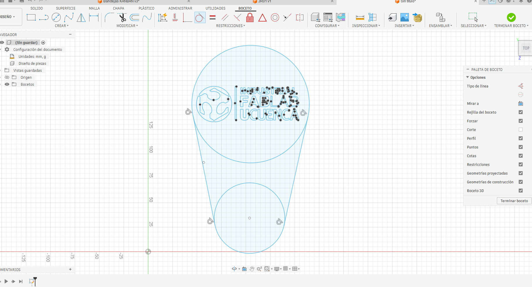
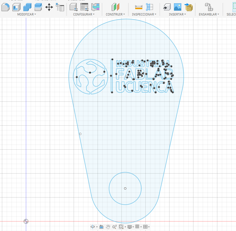
The design was developed in Fusion 360 as a compact metal tag. I started with a rounded outline that could work as a keychain or identification plate. A circular hole was added at the bottom so the piece could be attached to another object. In the upper area I placed the Industrial FabLab UCuenca logo and text, separating the design elements into two functional groups: external cutting geometry and internal engraving/cutting details.
This separation is important because the machine must interpret which paths cut through the metal and which paths only mark or engrave the surface. The outer contour and the circular hole define the final shape, while the logo and letters define the visual identity of the piece.
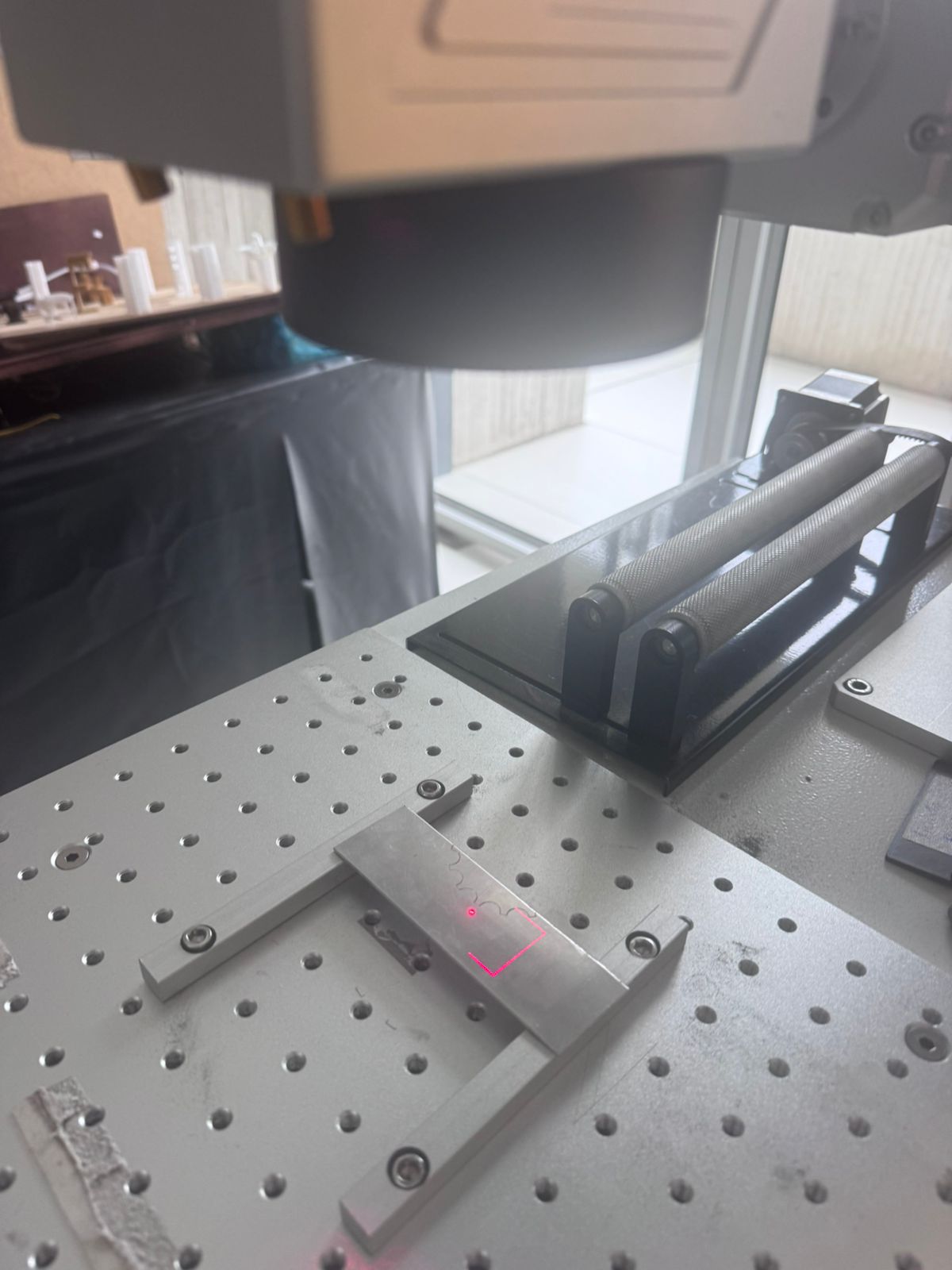
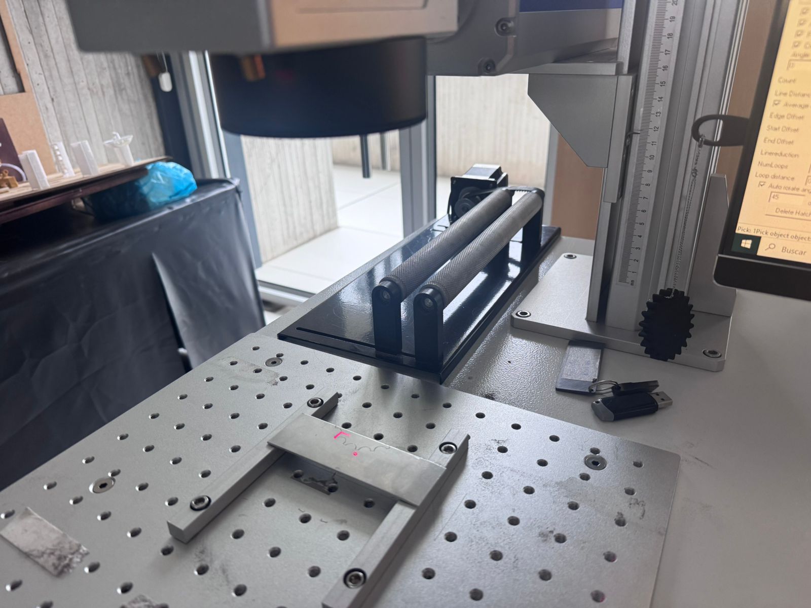
After finishing the digital design, the metal sheet was placed on the working table of the fiber laser machine. The material had to be positioned flat and stable so the focal distance remained constant during the operation. The preview beam was used to check the location of the design on the metal before starting the final cut.
At this stage, the operator calibrates the process according to the type of metal, thickness and expected result. The same fiber laser can behave differently depending on the selected speed, frequency and power. For this reason, the setup was treated as a controlled test: first checking alignment and then cutting the final geometry.
The cutting process was performed by running the programmed toolpath on the fiber laser machine. The beam followed the outline and internal details, removing material through concentrated thermal energy. During the process, the critical variables were laser power, speed and frequency, because together they determined whether the metal was only marked, engraved or fully cut.
The following videos show the operation of the machine while the metal piece is being processed. The visible laser path helps verify the correct alignment of the job and shows how the machine follows the digital geometry.
Before accepting the final result, I treated the fabrication as an iterative process. The goal was to check alignment, verify whether the small text could be reproduced, and adjust the cutting parameters so the contour could be separated from the sheet without excessive heat damage.
| Iteration | Parameters Tested | Observation | Decision |
|---|---|---|---|
| 1 - Alignment preview | Red preview frame, focus at material surface, 1 pass. | The geometry fit inside the metal sheet and the circular hole was correctly located. | Proceed to marking test. |
| 2 - Logo and text marking | 35% power, 800 mm/s, 30 kHz, 1 pass. | The logo and text became visible, but very small internal details needed more energy. | Use a stronger setting for internal details. |
| 3 - Internal detail cut | 75% power, 120 mm/s, 25 kHz, -0.3 mm focus, 3 passes. | Small details opened better, although the heat-affected zone increased slightly. | Keep the setting and avoid unnecessary extra passes. |
| 4 - External contour cut | 90% power, 80 mm/s, 20 kHz, -0.5 mm focus, 6 passes. | The external profile and attachment hole were released from the sheet. | Use this setting for the final metal tag. |
The test showed that the most critical balance was between speed and number of passes. A very fast speed produced incomplete cutting, while too many slow passes increased the heat mark around the edge. The final parameters were selected because they produced a complete cut while keeping the part usable as a small identification tag.
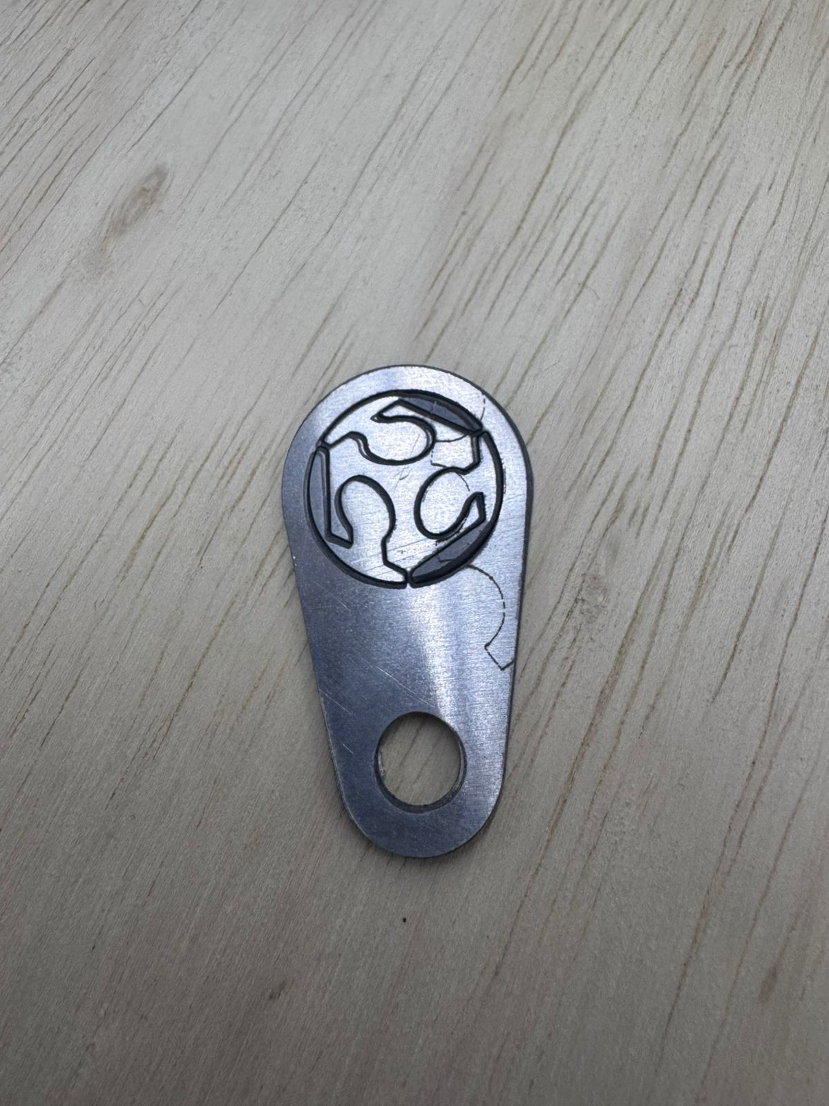
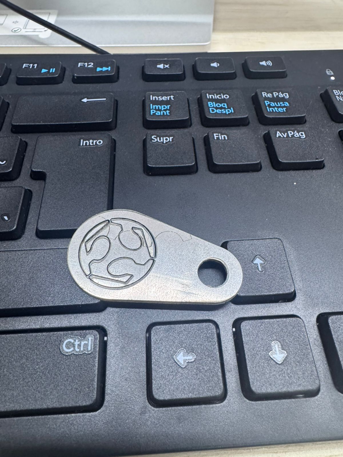
The final result was a small metallic tag with the FabLab UCuenca logo engraved/cut on the upper area and a circular hole for attachment. The piece shows the main advantage of the fiber laser process: it can create durable marks and precise contours directly on metal without the need for mechanical cutting tools.
The edge quality and surface finish depend strongly on the selected parameters. In this test, the result allowed me to compare the difference between marked details, cut contours and the heat-affected zones around the laser path.
The experiment confirmed that fiber laser cutting is a powerful option for small metal parts, especially when the design requires fine text, logos or identification marks. Compared with mechanical cutting, the process does not require a physical bit touching the material, so there is no tool wear in the conventional sense and the geometry can include very small details.
| Aspect evaluated | Observation |
|---|---|
| Detail quality | The logo and text could be reproduced on metal, although very small details require careful parameter tuning. |
| Cutting capability | The machine can cut metal when power, speed and frequency are calibrated correctly for the material thickness. |
| Alignment | The preview beam is essential to avoid placing the design outside the useful material area. |
| Learning value | The process expanded my understanding of digital fabrication beyond the regular Fab Academy machines. |
Working with fiber lasers requires strict safety procedures because the beam can be dangerous to the eyes and skin, and metal processing can generate fumes, reflections and hot surfaces. The work should be performed only with trained supervision, proper enclosure, ventilation and compatible protective equipment.
The original design files used for this wildcard assignment are available below. The 3MF and F3D files contain the editable design data, while the DXF file is included as a more universal 2D vector format for reproducing the metal tag in laser cutting or engraving software.
Download Wildcard 3MF File Download Fusion 360 F3D File Download DXF FileThis wildcard week was valuable because it allowed me to explore a technology outside the standard Fab Academy workflow. Fiber laser cutting showed me that metal fabrication requires a different mindset from cutting wood, acrylic or cardboard. The machine is very precise, but the quality of the final result depends on understanding the interaction between the beam and the material.
The most important lesson was that digital fabrication is not only about sending a file to a machine. The design, material, power, speed, frequency, focus and safety conditions all form part of the process. By testing this technology, I expanded my fabrication toolkit and gained a better understanding of how industrial marking and metal cutting can be integrated into future prototypes.