NODO

Integration of the complete Smart Lean Cell: mechanical workstation, sensors, custom PCB, software dashboard, user interaction, and electronics packaging.
The objective of this week was to integrate the electronic system into the final project in a clean, safe, and functional way. For this task I designed a case that holds the custom PCB of the project and organizes the wiring that connects the board with the motion sensor used in the Smart Lean Cell.
The case was designed in Fusion 360 and fabricated with a Bambu Lab 3D printer. The final object protects the PCB, keeps the connectors accessible, and allows the electronics to be presented as part of the final system instead of remaining loose on the table.
Before fabricating the enclosure, I defined a system integration plan for the Smart Lean Cell. The goal was to transform the electronics from a set of exposed components into a packaged subsystem that could be installed, inspected, connected, and presented as part of the final product. This plan considered the PCB footprint, the XIAO ESP32-C3 USB-C access, HC-SR04 sensor wiring, power lines, cable routing, visibility, maintenance, and the physical position of the module inside the final workstation.
| Checklist Item | Status | Evidence in this Documentation |
|---|---|---|
| Made a plan for system integration for the final project. | Completed | The integration plan is described above as a five-step process from interface definition to reproducibility. |
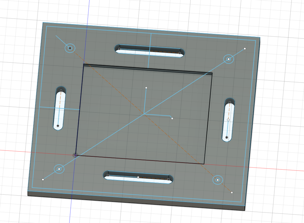
| Documented the plan with CAD and/or sketches for system integration. | Completed | The Fusion 360 screenshots show the PCB footprint, mounting slots, internal cavity, cable openings, and final enclosure geometry. |
| Implemented methods of packaging. | Completed | The 3D printed case packages the PCB, protects the electronic board, routes the cables, and keeps the USB-C connector accessible. |
| Designed the final project to look like a finished product. | Completed | The electronics are installed as a visible module in the Smart Lean Cell instead of remaining as loose wires and an exposed board. |
| Documented system integration of the final project. | Completed | This page documents the complete Smart Lean Cell architecture, integration flow, functional tests, BOM, CAD process, 3D printing, assembly, packaging decisions, final integration photos, and videos. |
| Linked to system integration documentation from the final project page. | Completed | The Final Project page includes a direct link back to this Week 16 System Integration documentation. |
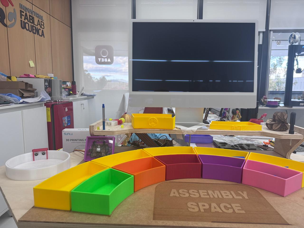
The system integration work was not limited to designing a protective enclosure. The enclosure was one subsystem inside the complete Smart Lean Cell, a learning station where children interact with an assembly process while the electronics measure what happens in real time. The complete integration connects the physical workstation, the organized Lean tools, the sensing system, the custom PCB, the embedded firmware, the Blynk dashboard, and the user feedback elements.
The diagram below shows how the main subsystems interact. The child performs the assembly activity in the workstation, the sensors detect inventory and finished parts, the PCB processes the signals with the XIAO ESP32-C3, and the software layer sends live values to the dashboard. The case designed in this week packages and protects the control board so it can be safely installed as part of the final product.
| Subsystem | Connected To | Interface Type | Integration Purpose |
|---|---|---|---|
| Kanban trays and assembly board | User and sensors | Physical interaction | Organizes the learning activity and defines where parts enter, move, and finish. |
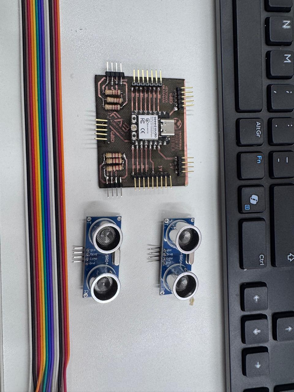
| HC-SR04 sensors | Custom PCB | Digital trigger/echo signals | Detects part presence at inventory and finished stations. |
| Custom PCB | XIAO ESP32-C3, sensors, LEDs, cables | Electrical and signal routing | Centralizes wiring and protects the microcontroller inputs with voltage dividers. |
| 3D printed enclosure | PCB and workstation | Mechanical packaging | Protects the electronics and fixes the controller in a visible, serviceable position. |
| Firmware | Sensors, LEDs, Blynk | Embedded logic | Calculates cycle time and converts sensor events into learning indicators. |
| Blynk dashboard | XIAO ESP32-C3 through WiFi | IoT communication | Displays real-time performance and supports user evaluation of the process. |
To validate system integration, I checked that the mechanical station, sensors, PCB, firmware, dashboard, and user interaction worked together. The goal was not only to verify that the printed enclosure fit the PCB, but also to confirm that the packaged electronics could operate inside the Smart Lean Cell while the user performs the assembly activity.
| Test | What Was Verified | Expected Result | Observed Result |
|---|---|---|---|
| PCB packaging and cable routing | The custom PCB fits inside the case and the sensor cables exit without stress. | The board remains fixed, visible, and accessible for USB-C programming. | The PCB was mounted correctly and the connector area remained accessible. |
| Sensor to PCB test | The HC-SR04 sensor connects to the PCB and sends stable signals to the XIAO ESP32-C3. | The firmware reads distance values without loose wiring or exposed connections. | The sensor wiring stayed organized through the packaged module. |
| Firmware and dashboard test | The ESP32-C3 processes sensor data and sends values to Blynk through WiFi. | The dashboard updates cycle values and process status in real time. | The dashboard was used as the monitoring layer for the final Smart Lean Cell. |
| User interaction test | A learner interacts with the assembly station while the system monitors the process. | The user can assemble parts while the electronics measure and display process information. | The workstation, storage modules, sensor, PCB case, and dashboard worked as one demonstrator. |
The integration required the mechanical case, the electronic control board, and the components needed to connect the sensing system. The BOM was kept simple because the goal was to make the electronic subsystem easier to mount, inspect, and maintain.
| Component | Quantity | Function in the System |
|---|---|---|
| Custom PCB | 1 | Main electronic board of the project. It holds the XIAO module, headers, resistors, and connection points. |
| Seeed Studio XIAO ESP32-C3 | 1 | Microcontroller used to read sensor data and communicate with the rest of the project system. |
| HC-SR04 ultrasonic motion/distance sensor | 1 | Detects object presence or movement near the assembly area. |
| Ribbon cables and jumper wires | Several | Connect the PCB with the sensor and external parts of the prototype. |
| 3D printed PCB case | 1 | Protects the PCB and organizes cable routing inside the final project. |
| PLA filament | As needed | Material used to fabricate the case on the Bambu Lab printer. |
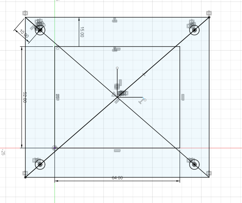
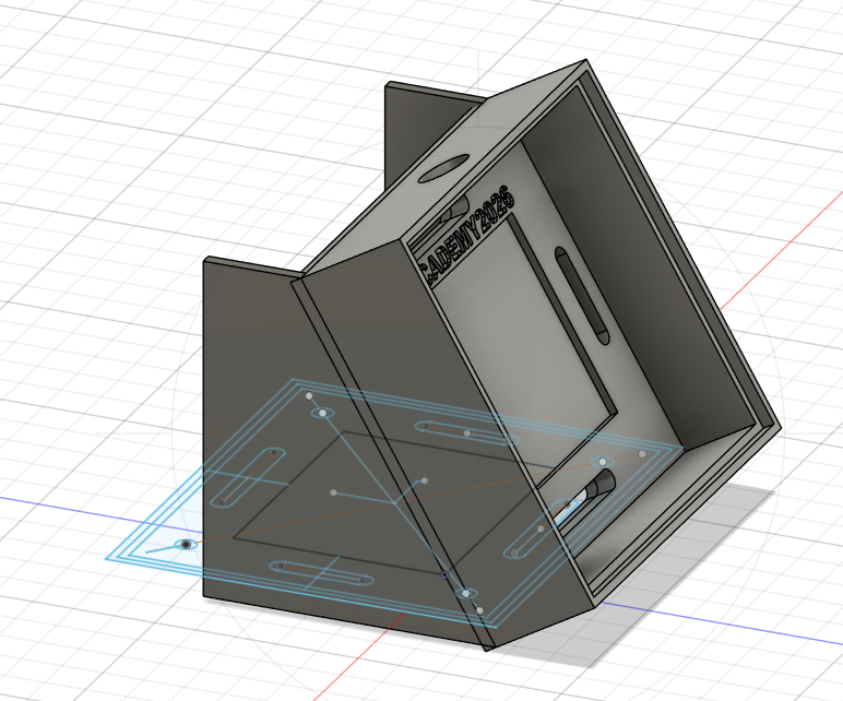
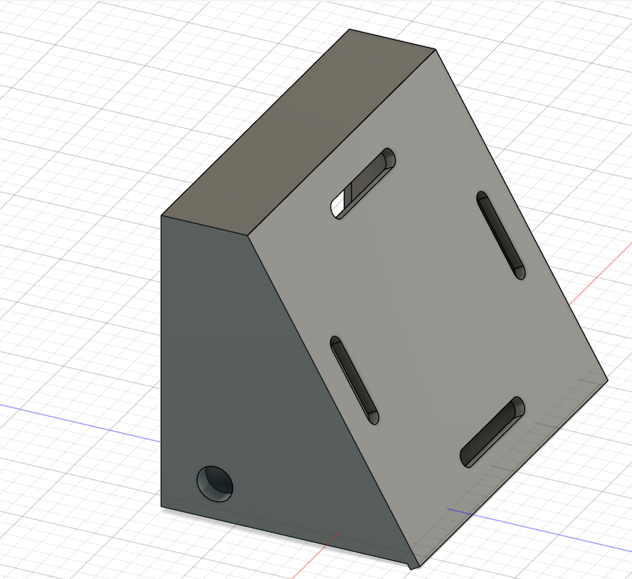
The design started by measuring the PCB and defining the internal volume required to place the board without pressing the headers or the USB-C connector. The case needed enough clearance for the cable connectors, the sensor wires, and the power/programming cable. For this reason, the design includes side and rear openings for routing cables.
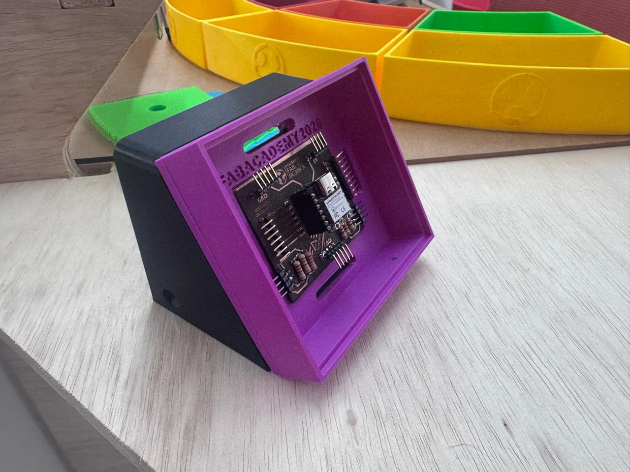
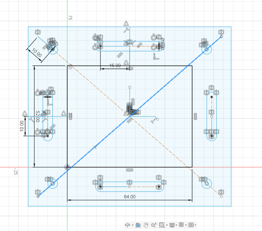
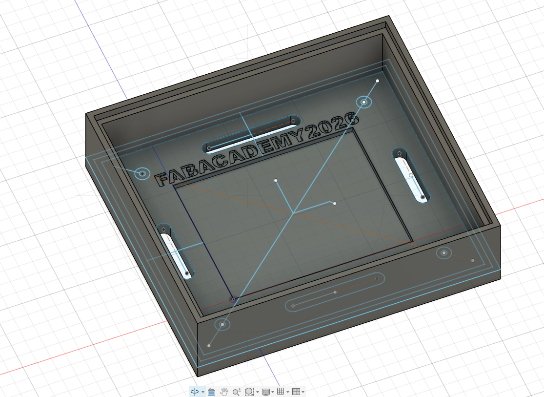
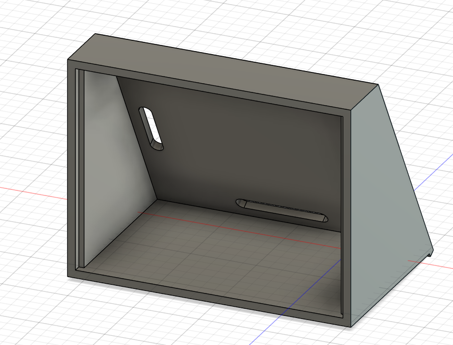
In Fusion 360 I first created a rectangular sketch based on the PCB footprint. Then I added the external frame, the internal cavity, mounting slots, and a front opening that allows the board to be visible. The case also has an inclined body so the PCB can be presented at a readable angle in the final project.
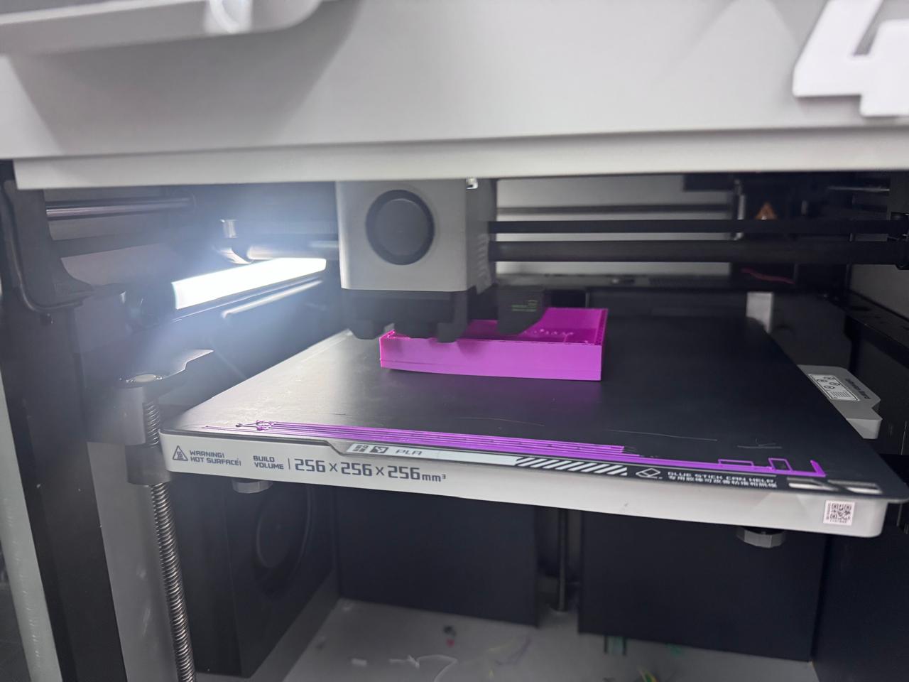
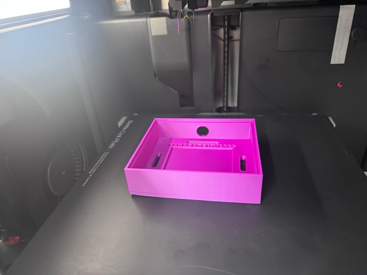
After finishing the model, the case was exported for 3D printing and prepared for fabrication on a Bambu Lab printer. PLA was selected because it is rigid, easy to print, and strong enough for a protective electronics enclosure. The print was oriented so the main cavity remained clean and the front frame had a good surface finish.
During printing, I checked the first layers and the adhesion to the build plate. This was important because the case has a flat base, thin walls, and long slots that need to remain dimensionally stable to fit the PCB correctly.
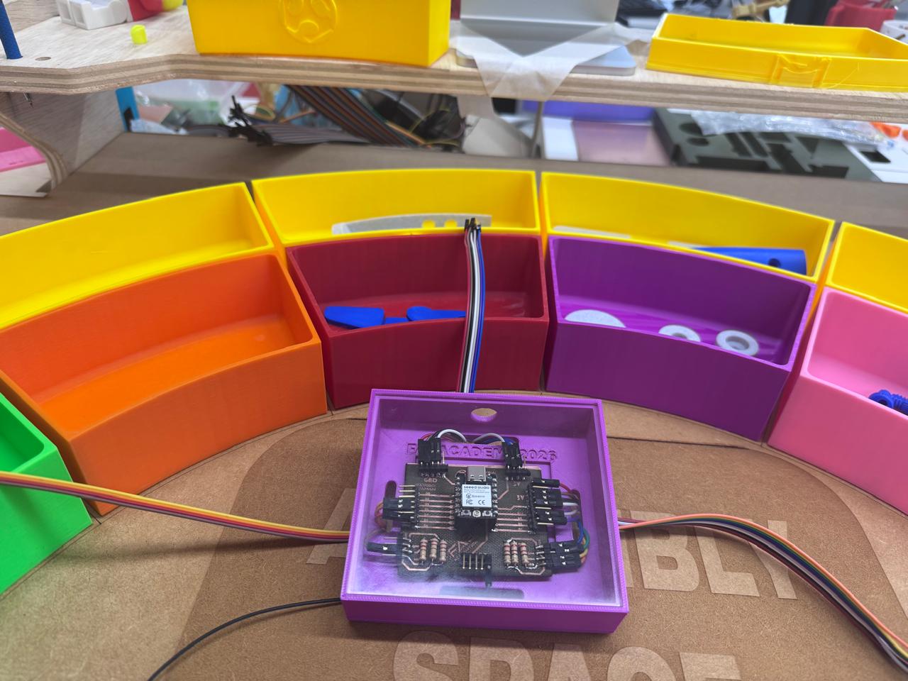
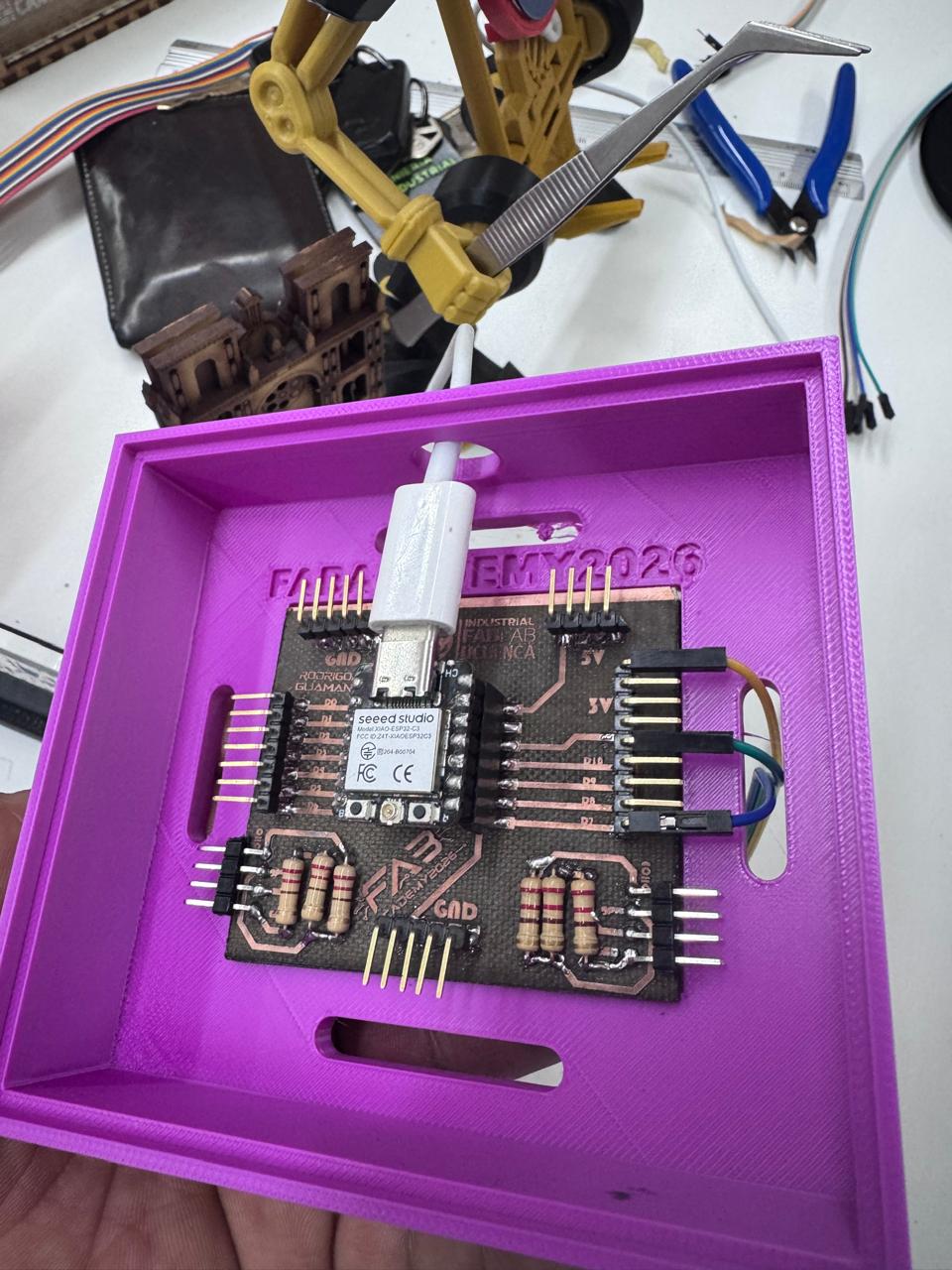
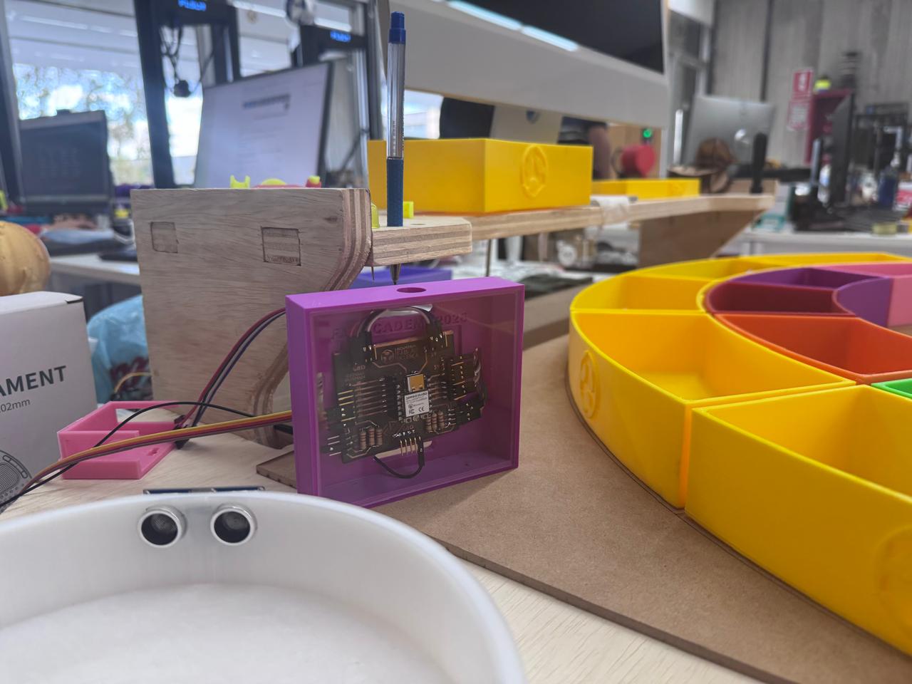
Once the print was finished, the PCB was placed inside the case to check the fit. The board was aligned with the internal rectangular area and the slots were used to route the cables without bending them sharply. The front opening makes it possible to inspect the PCB, verify the connections, and access the USB-C port of the XIAO ESP32-C3.
The HC-SR04 sensor was connected to the PCB using jumper wires. The sensor was positioned in the final project so it could detect object presence near the assembly area. The case works as the electronic control module of the project: it groups the board, protects it, and separates the electronics from the moving or handled parts of the prototype.
The final integration connects the mechanical, electronic, and sensing parts of the project. The printed case gives the PCB a defined location inside the Smart Lean Cell, while the HC-SR04 sensor detects movement or object presence near the working area. This makes the electronics easier to present, debug, and protect during demonstrations.
The case also improves the visual presentation of the final project. Instead of showing loose wires and an exposed PCB, the electronics are organized as a module that belongs to the system. This is important because the final project is not only a set of separate parts; it must work as one integrated prototype.
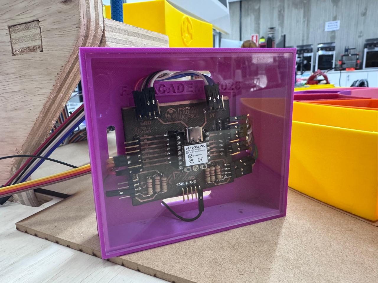
The packaging method was based on a simple requirement: the electronic system had to be protected without hiding its function. For this reason, the PCB is visible from the front of the case, but the board is no longer exposed to direct handling. The enclosure creates a defined boundary between electronics, cables, sensors, and the learner interaction area of the Smart Lean Cell.
| Packaging Requirement | Design Decision | Result |
|---|---|---|
| Protect the PCB during demonstrations. | Rigid PLA enclosure with a front frame and internal cavity. | The board is held in a stable position and is less exposed to accidental contact. |
| Keep connectors serviceable. | Open front and cable slots for USB-C and jumper wires. | The electronics can be programmed, powered, inspected, and rewired without removing the full module. |
| Make the product look finished. | Inclined case geometry, visible PCB, clean cable routing, and consistent placement in the final station. | The electronic subsystem reads as part of the product rather than a temporary prototype. |
| Support reproducibility. | Publish 3MF and STL versions of the case files. | The case can be fabricated again using common slicers and 3D printers. |
The printable case files are available below. The 3MF files preserve the slicer-ready geometry used for the PCB enclosure, while the STL files provide a more universal format that can be opened in most CAD viewers and 3D printing slicers. Both formats are included to improve accessibility and reproducibility.
This week helped me transform the electronics from a functional prototype into an integrated subsystem for the final project. Designing the case in Fusion 360 allowed me to consider the real size of the PCB, the position of the connectors, cable routing, and presentation inside the Smart Lean Cell.
The Bambu Lab 3D print produced a rigid case that protects the board and makes the electronic module easier to install. The final result integrates the custom PCB, cables, HC-SR04 sensor, and printed enclosure into a more organized and professional system.
The final functional test was carried out to verify that the Smart Lean Cell worked as a complete integrated system instead of isolated subsystems. In this test, the user interacted physically with the workstation while the sensor, custom PCB, embedded firmware, software interface, and final project structure operated at the same time. This evidence is important because system integration is successful only when the mechanical, electronic, programming, and interaction layers respond together during a real use sequence.
| System Layer | Role During the Test | Integration Evidence |
|---|---|---|
| User interaction | The user manipulates the workstation and performs the activity in the physical cell. | The prototype responds while the user interacts with the learning station. |
| Sensor input | The HC-SR04 sensor detects object presence or movement in the working area. | The sensing event is triggered during the activity, not as a separate bench test. |
| Custom PCB | The PCB receives the sensor wiring and organizes the connection to the XIAO ESP32-C3. | The board works inside the printed case with the cables routed as part of the final assembly. |
| Embedded firmware | The microcontroller reads the sensor signal, interprets the event, and updates the system variables. | The firmware runs while the physical interaction is happening. |
| Software interface | The software layer receives or displays the process information generated by the electronics. | The test confirms that the physical action can be translated into digital feedback. |
During the test, the interaction starts at the physical workstation. The user performs the activity in the Smart Lean Cell, which creates a real event in the sensing area. The HC-SR04 sensor acts as the input device and detects the presence or movement related to the task. This signal is not handled with loose temporary wiring; it is routed through the custom PCB installed inside the 3D printed enclosure. This confirms that the packaging solution is functional, because the electronics remain protected while still allowing the sensor and cables to operate.
The XIAO ESP32-C3 on the PCB processes the sensor information through the embedded firmware. The firmware converts the sensor reading into useful system data, such as object detection or process state. At the same time, the software interface receives the information from the electronic layer and gives feedback to the user. This closes the integration loop: a physical action produces a sensor event, the PCB and firmware process it, and the software presents the result as part of the learning experience.
This simultaneous test also helped validate the mechanical integration. The PCB case keeps the board in a fixed position, the cable exits prevent stress on the connectors, and the sensor remains aligned with the working area. Because all subsystems operate together during the demonstration, the result shows that the project is no longer only a collection of fabricated parts. It behaves as a coordinated system where hardware, software, packaging, sensing, and user interaction support the same educational goal.