NODO

2D, 3D, AI and Multimedia Tools
The objective of this week in Fab Academy is to explore and document a wide range of digital tools rather than mastering a single one. These tools were used to model experimental objects, document the design process, compress image and video files, and preserve original design files as part of a transparent and reproducible workflow.
| Type | Software |
|---|---|
| Raster | GIMP |
| Raster | MyPaint |
| Vector | Inkscape |
| Vector | CorelDRAW |
| Type | Software |
|---|---|
| CAD / Modeling | Tinkercad |
| CAD / Modeling | Fusion 360 |
| 3D Modeling | Blender |
| CAD (Cloud) | Onshape |
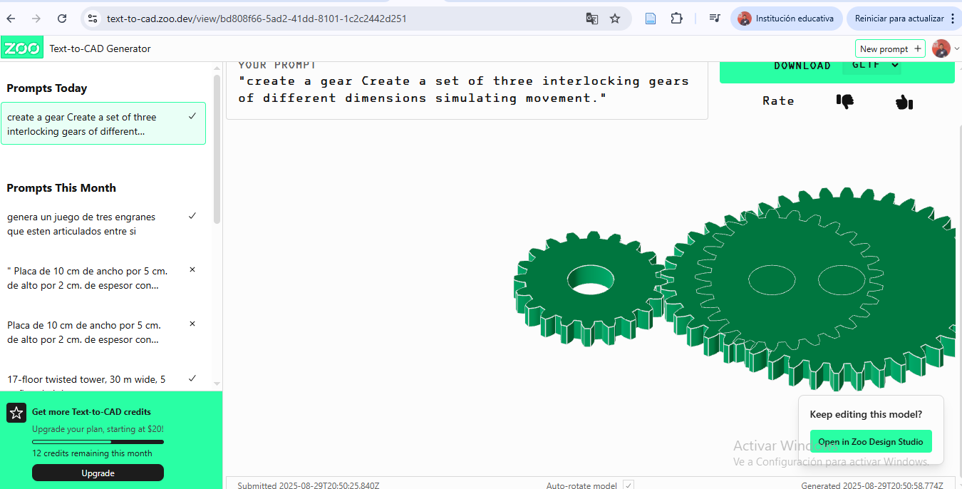
| AI (3D/Images) | Text to CAD |
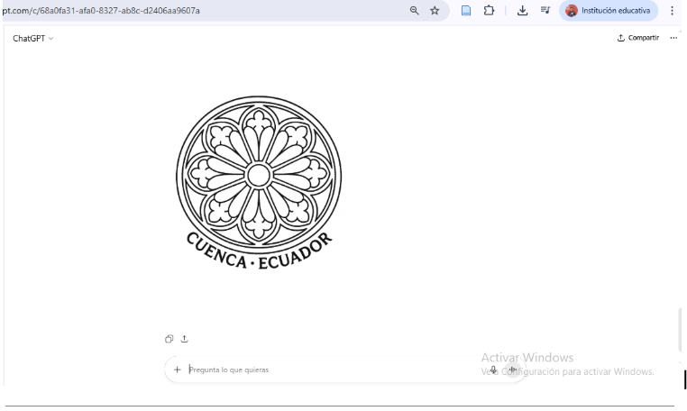
| AI (Images) | DALL·E |
| Type | Software |
|---|---|
| Video Editing | After Effects |
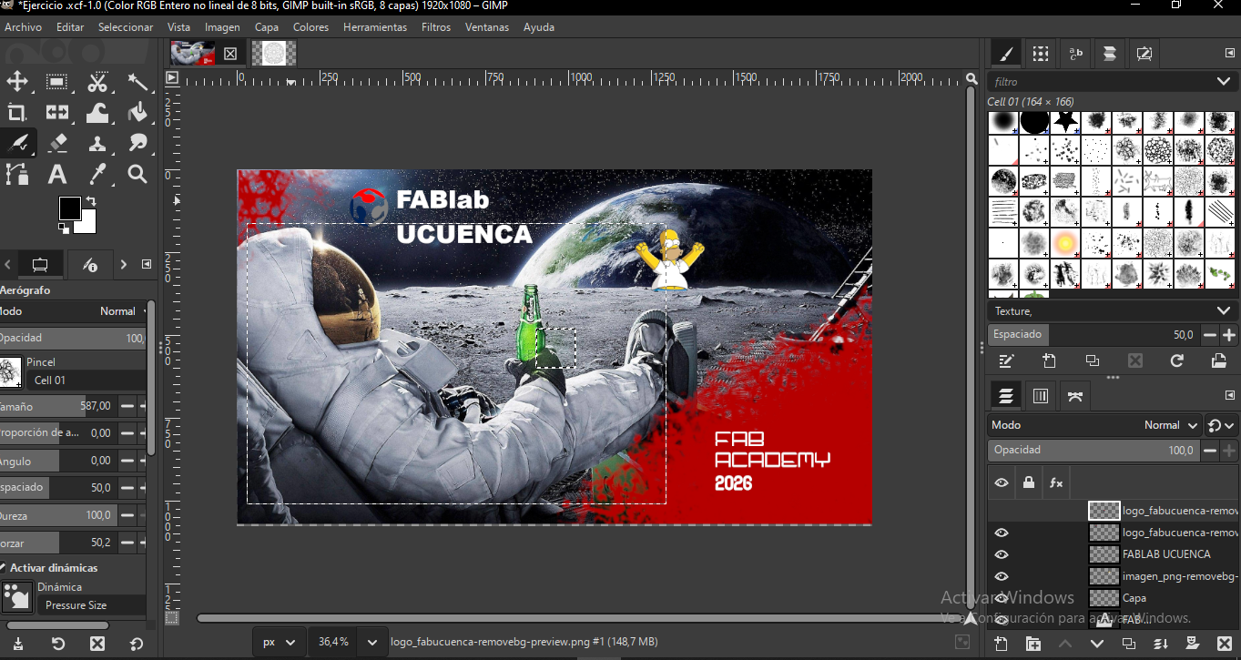
GIMP was used to edit screenshots, photographs, and documentation images. Image compression was performed to reduce file size while maintaining visual clarity for web publication.

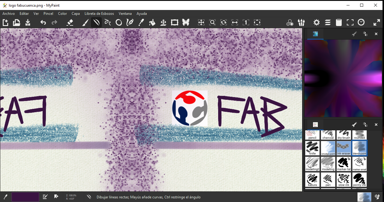
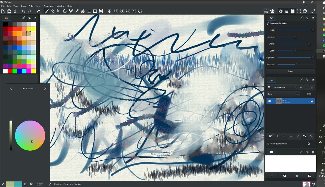
MyPaint supported early-stage ideation through freehand digital sketches, enabling rapid visualization of project concepts.
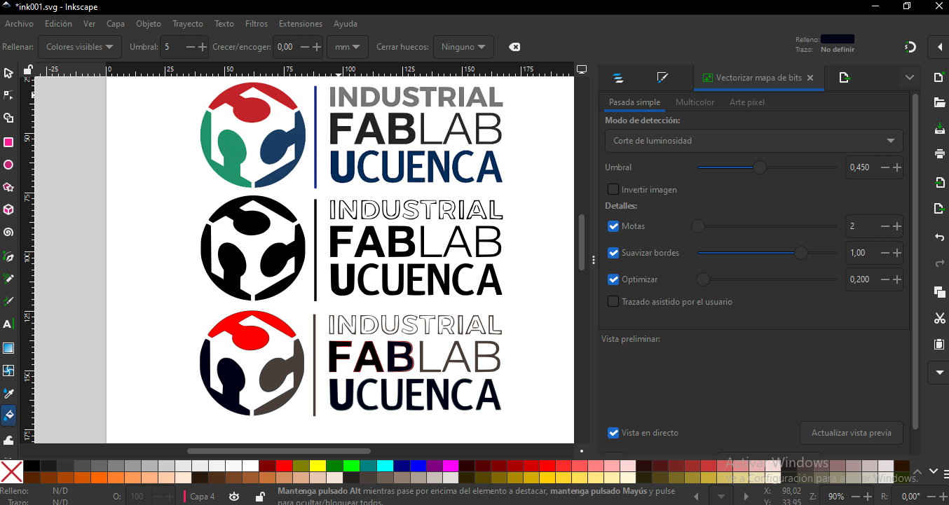
Inkscape was used to create vector files for laser cutting and technical diagrams, ensuring scalable and machine-readable designs.

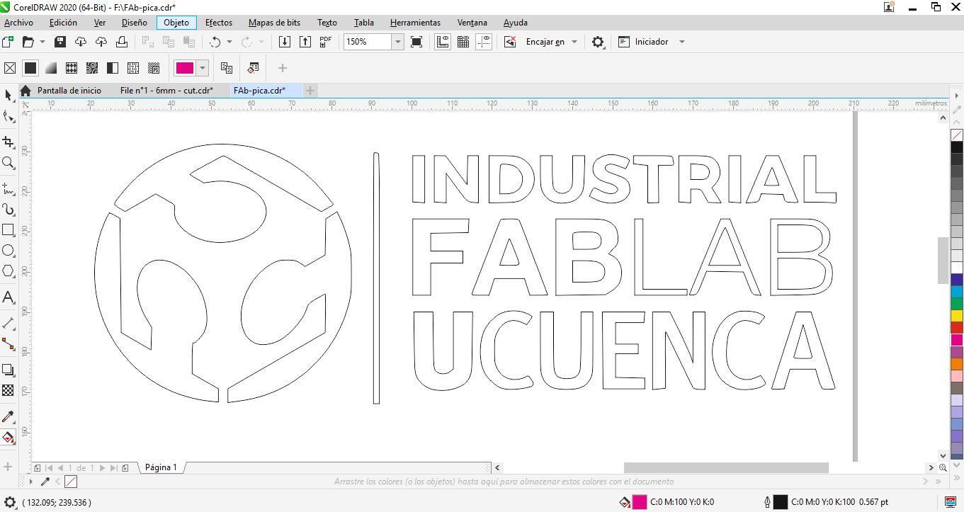
CorelDRAW was explored as an alternative vector platform, particularly useful for complex laser cutting layouts.
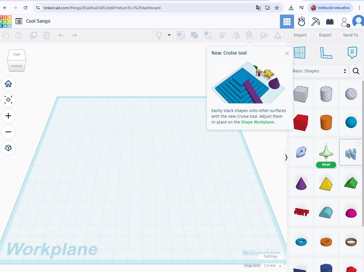
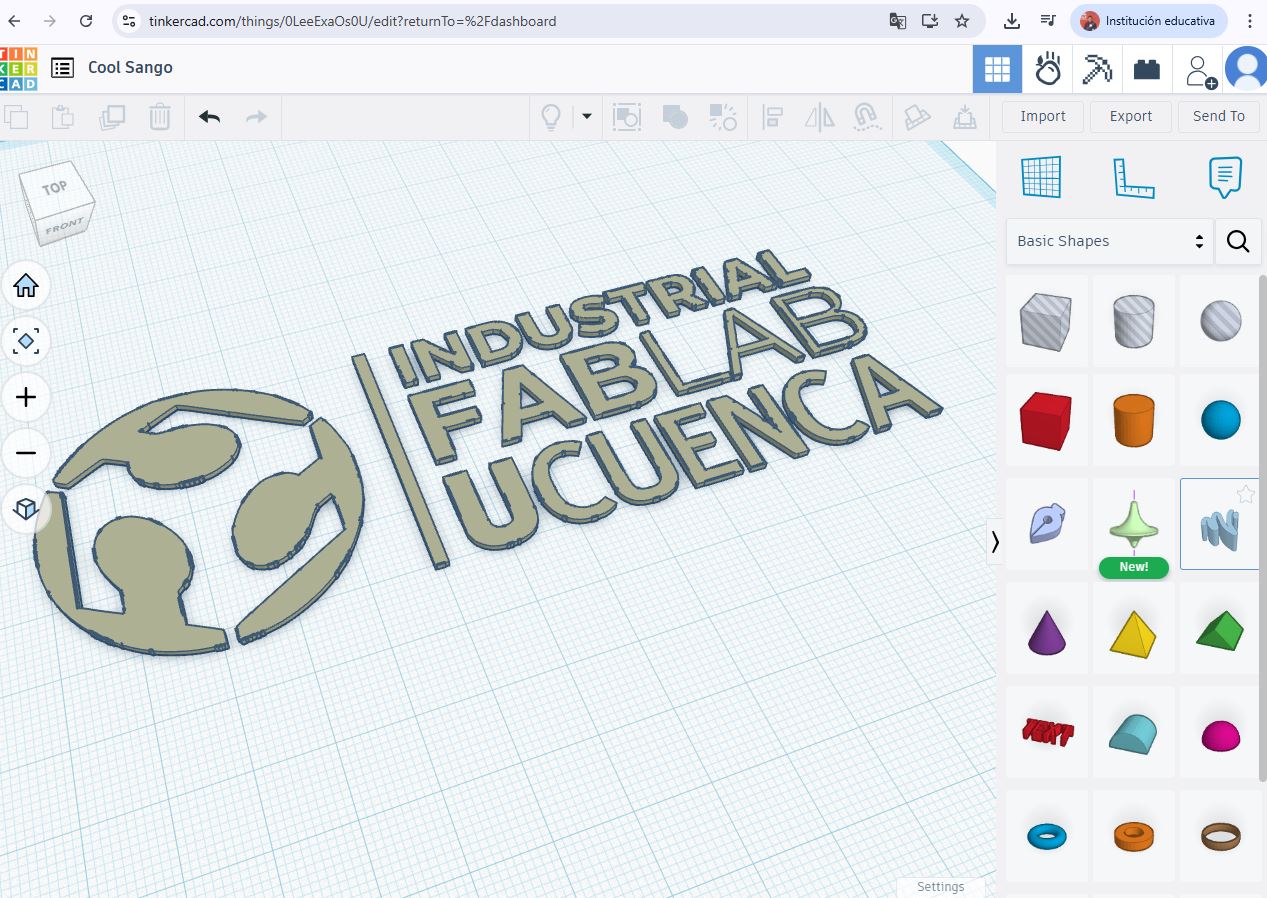
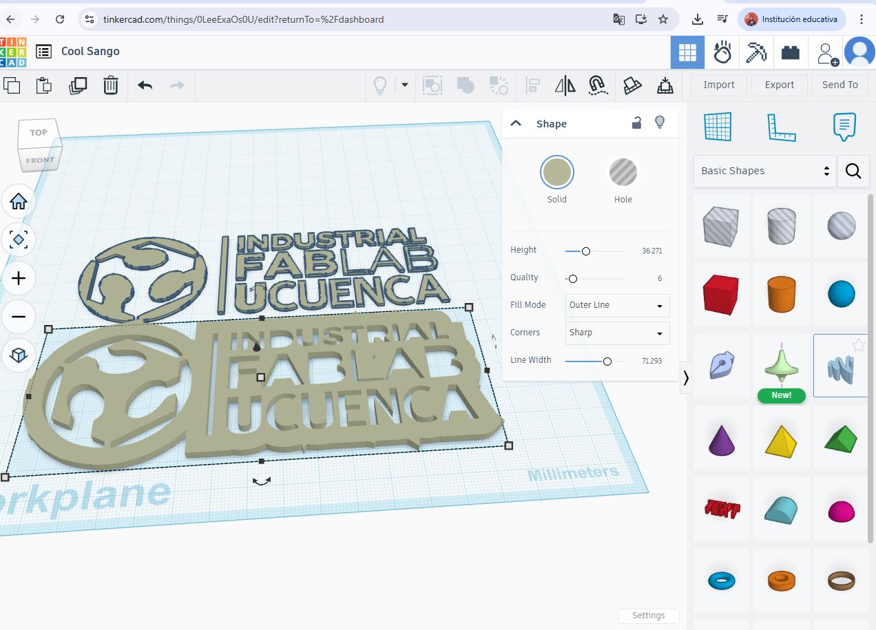
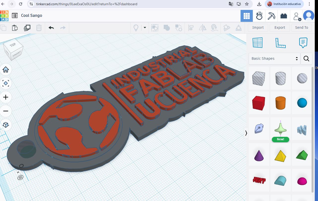
Tinkercad enabled rapid modeling of simple experimental objects and early components of a possible final project.
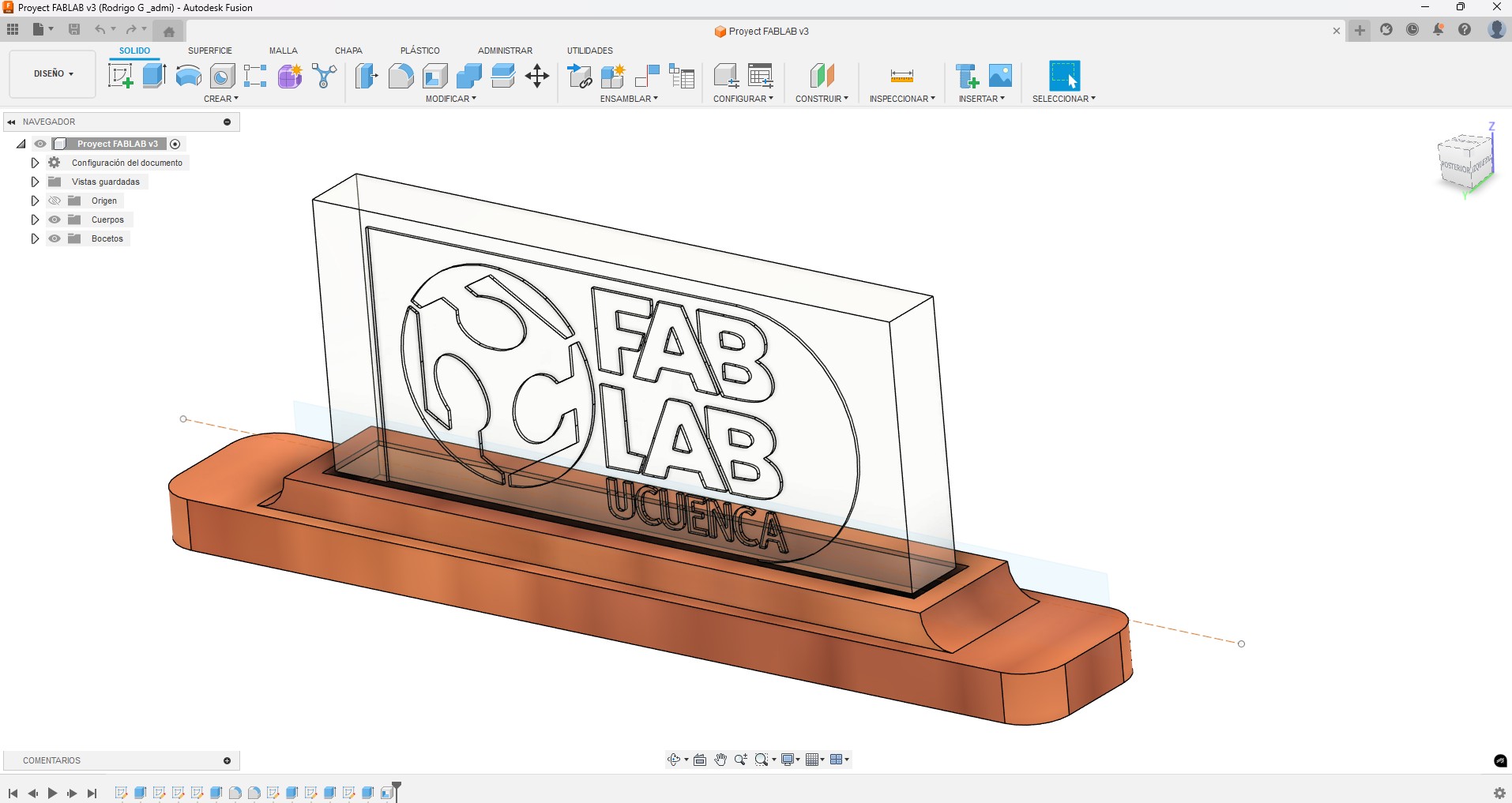
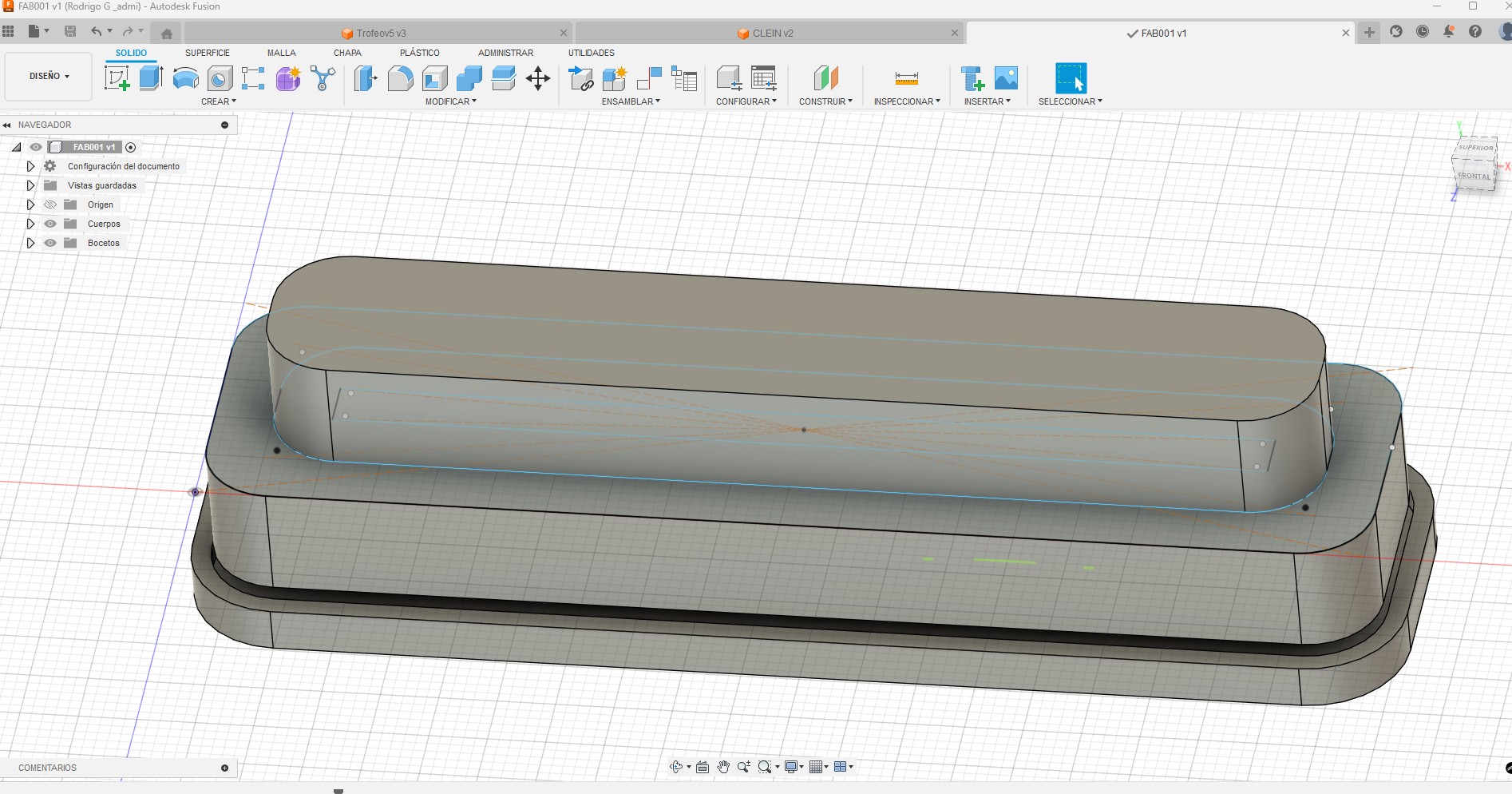
Fusion 360 was used for parametric and fabrication-oriented modeling, supporting precise dimensions and iterative design.
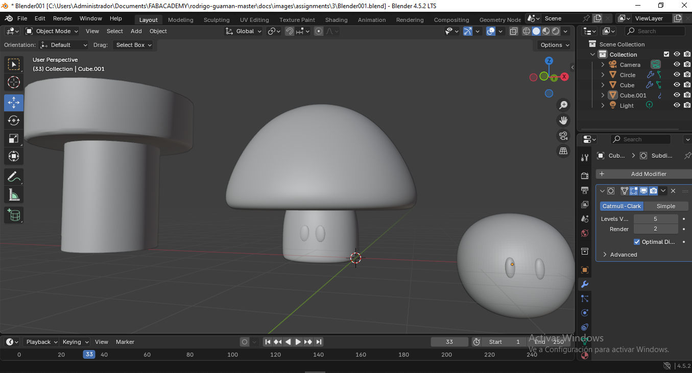
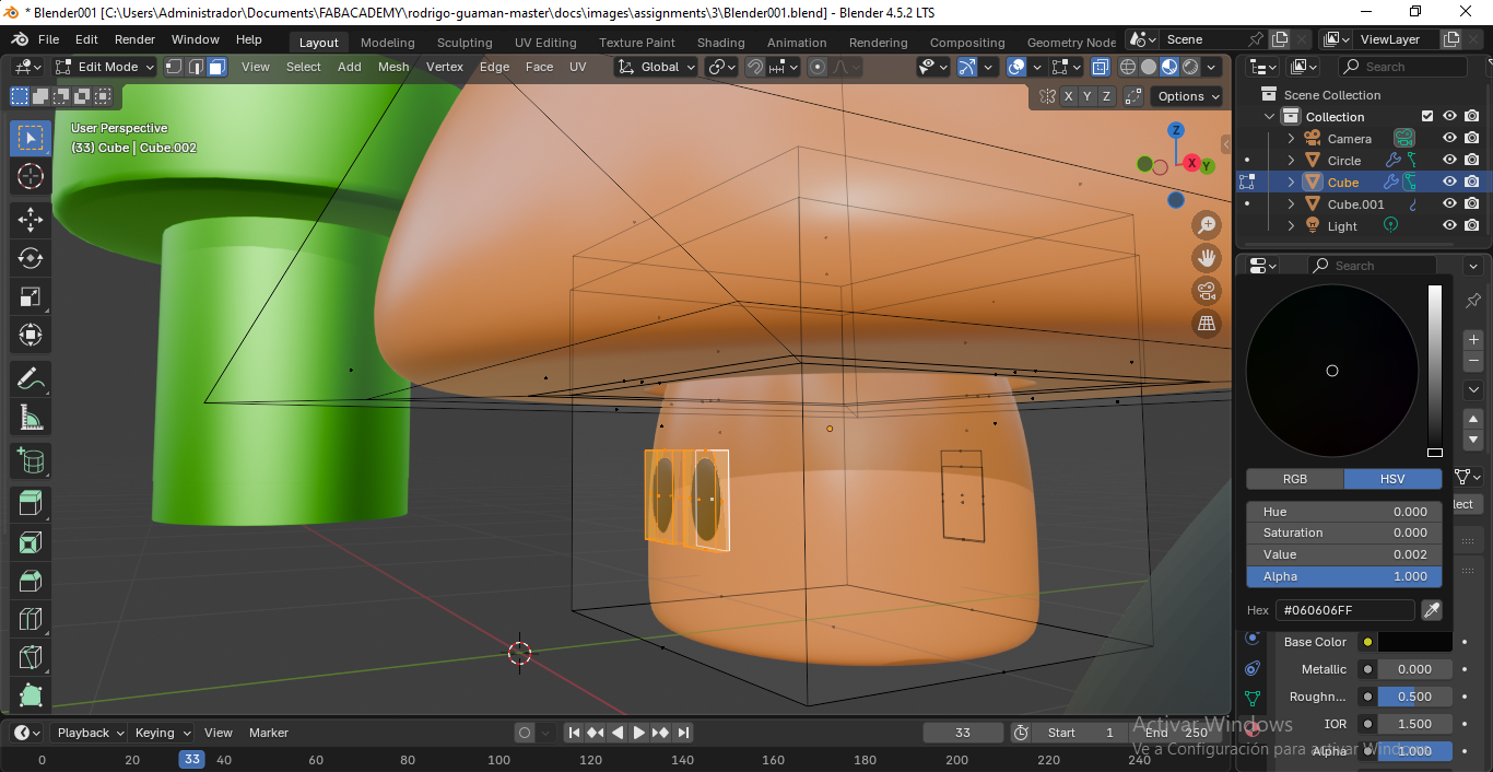
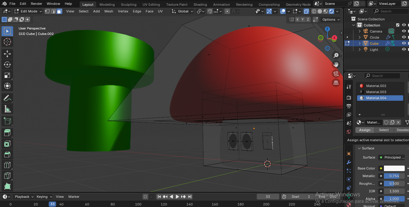
Blender was explored for mesh-based and organic modeling, expanding creative possibilities beyond parametric CAD tools.
Onshape was tested as a cloud-based CAD platform with built-in collaboration and version control.
Text-to-CAD tools were used to explore AI-assisted 3D generation from textual descriptions, mainly for conceptual reference.
DALL·E supported ideation by generating visual references that helped explore form and aesthetics.
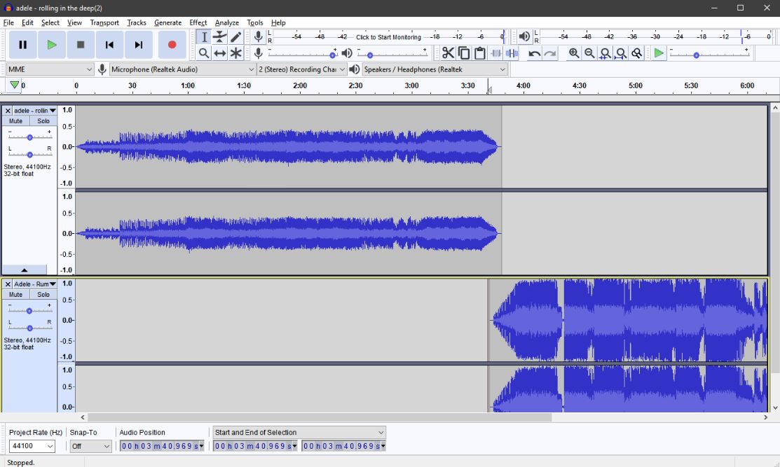
Audacity is an open-source audio editing software widely used for recording, editing, and compressing sound files. In the context of Fab Academy, Audacity is especially useful for documenting projects through voice explanations, narration of design processes, and audio integration in video documentation.
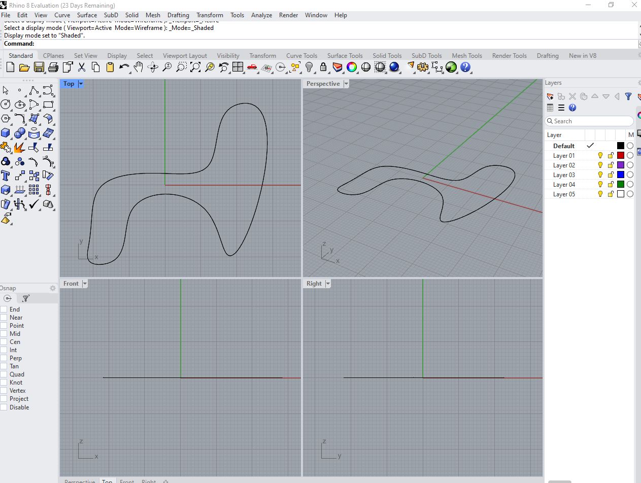
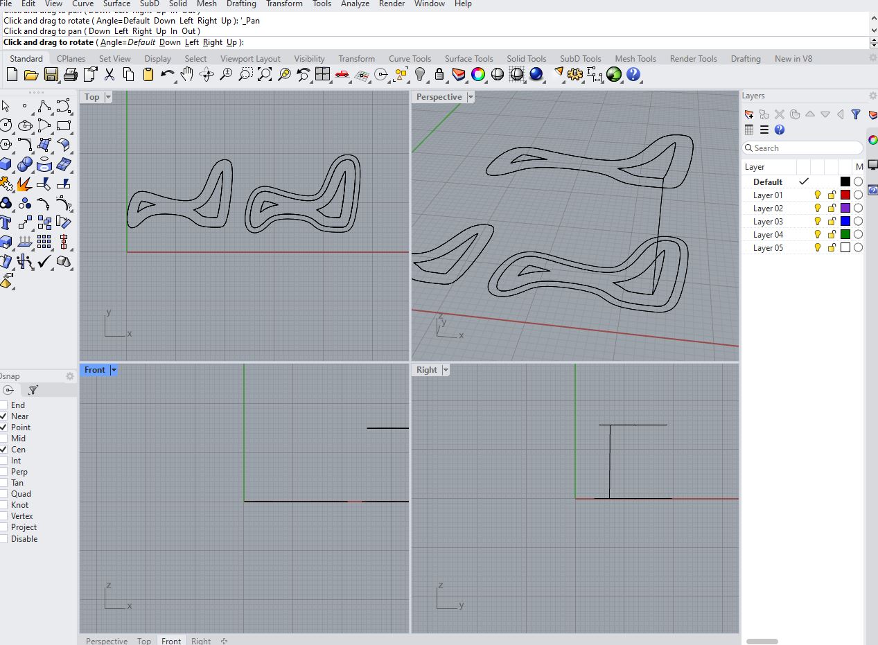
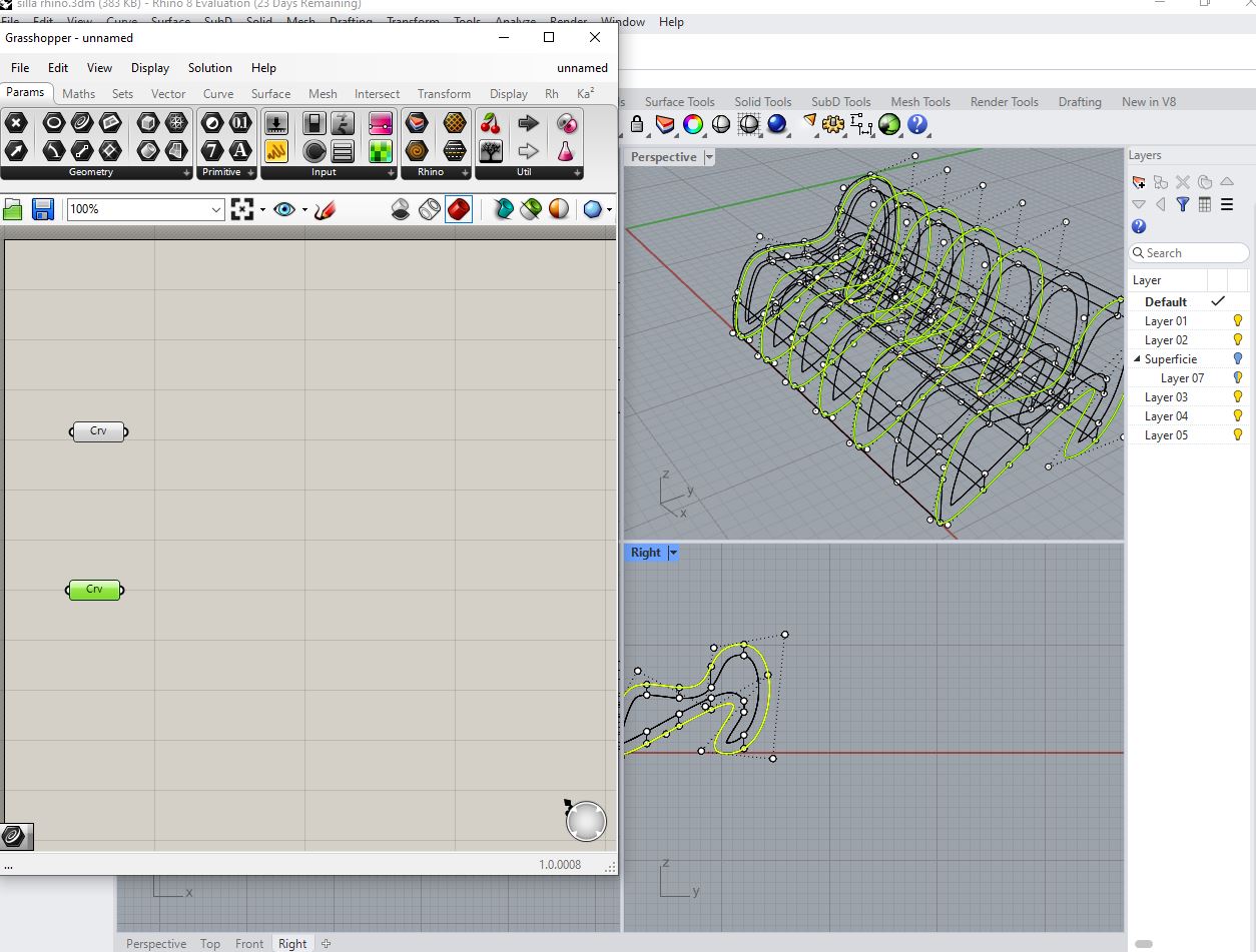
Rhinoceros (Rhino) is a NURBS-based 3D modeling software widely used in architecture, industrial design, and digital fabrication due to its precision, flexibility, and compatibility with fabrication workflows. Unlike purely parametric CAD tools, Rhino allows the designer to freely combine intuitive geometric modeling with exact dimensional control, making it especially suitable for experimental and fabrication-oriented projects.
In this exploration, Rhino was used as the primary modeling environment for the development of a parametric chair. The base geometry of the chair—such as the seat surface, structural ribs, and overall proportions—was first defined using curves, surfaces, and reference planes. This approach allowed quick iteration over form and ergonomics while maintaining precise control over dimensions relevant to digital fabrication processes such as CNC milling or laser cutting.
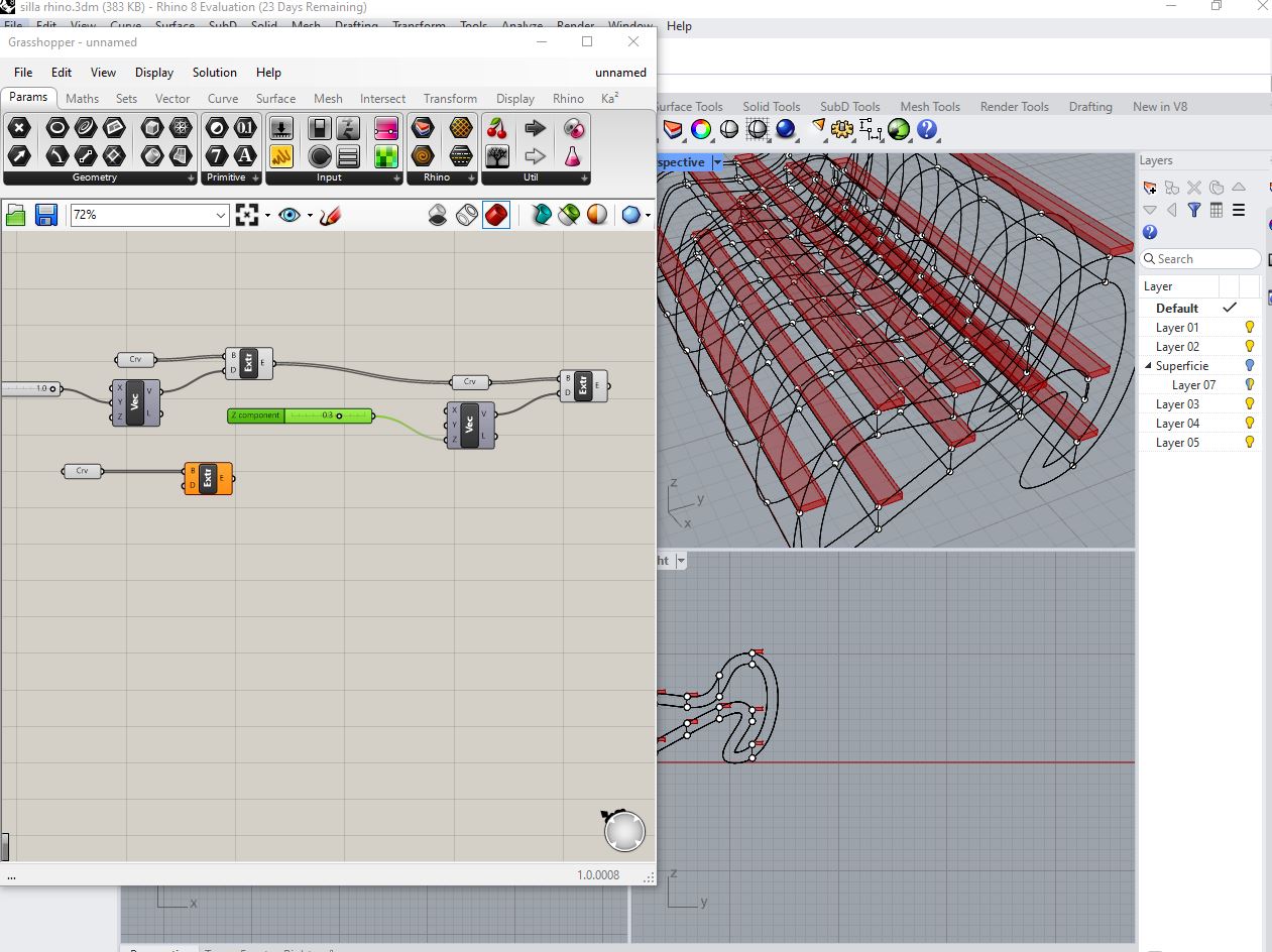
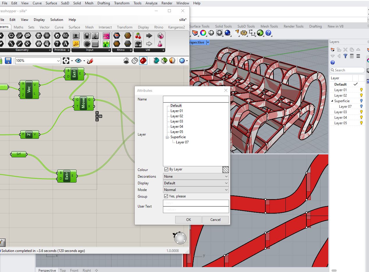
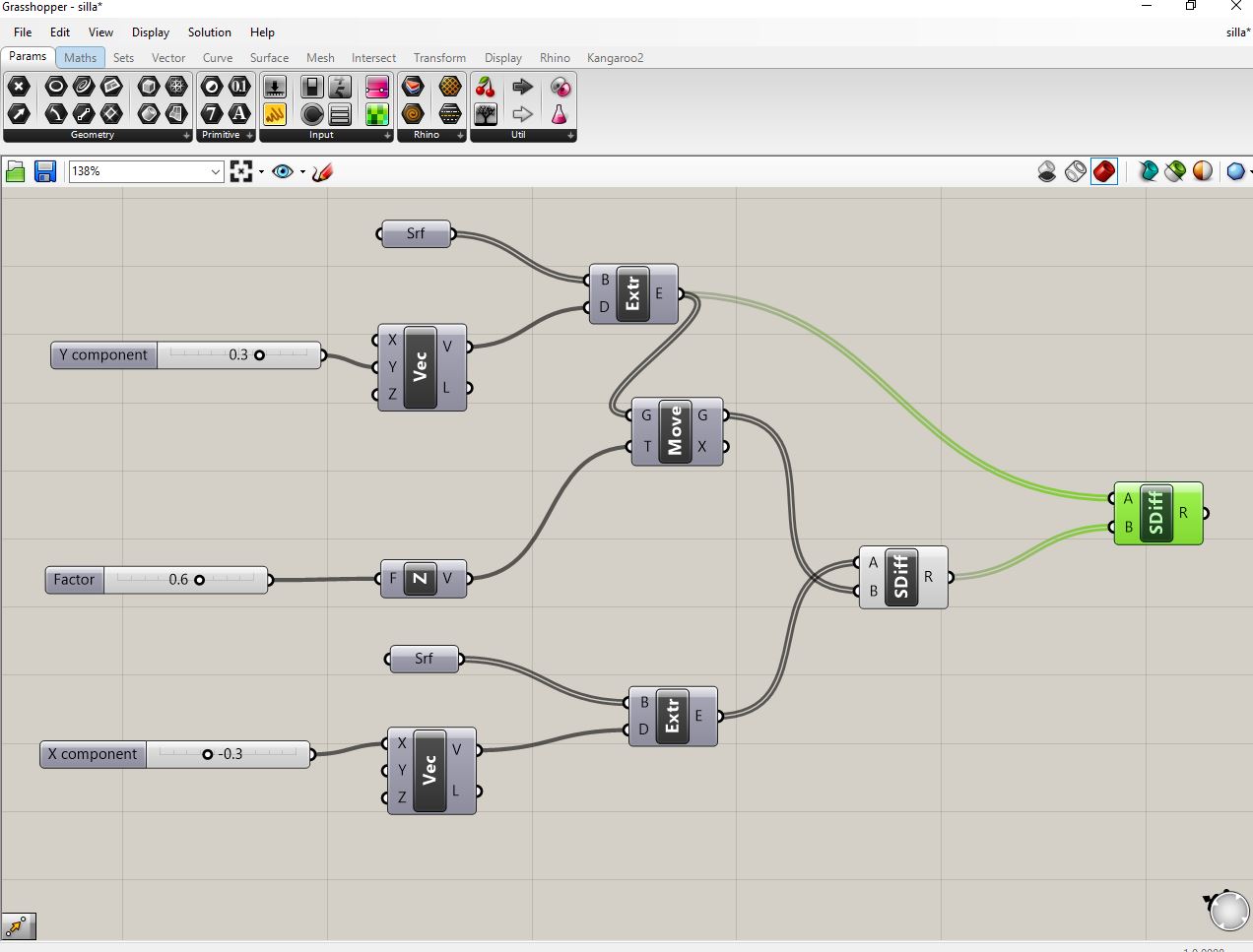
Grasshopper was used as a complementary visual programming tool to introduce parametric logic into the chair design. Through Grasshopper, key parameters such as seat height, curvature radius, material thickness, spacing between structural elements, and overall width were defined as variables. By modifying these inputs, multiple design variations of the chair could be generated automatically without rebuilding the model from scratch.
This parametric workflow is particularly valuable in Fab Academy because it encourages design exploration, optimization, and adaptability. The same chair model can be adjusted to different users, materials, or fabrication constraints by simply changing numerical values in Grasshopper. The final geometry generated in Rhino can then be exported as DXF, STL, or other fabrication-ready formats, ensuring a seamless transition from design to manufacturing.
Start by opening Rhino and setting the correct units (millimeters recommended for fabrication). Begin with simple reference geometry such as rectangles and lines to define the seat, backrest, and leg proportions. Use the Top and Front views to establish the main dimensions and ergonomic scale.
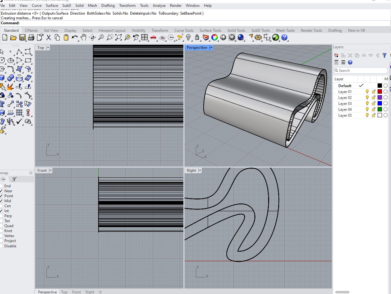
Use commands such as ExtrudeCrv, Loft, or Sweep to generate surfaces from the base curves. Define the seat and backrest curvature carefully, ensuring smooth transitions and proper alignment between structural elements.
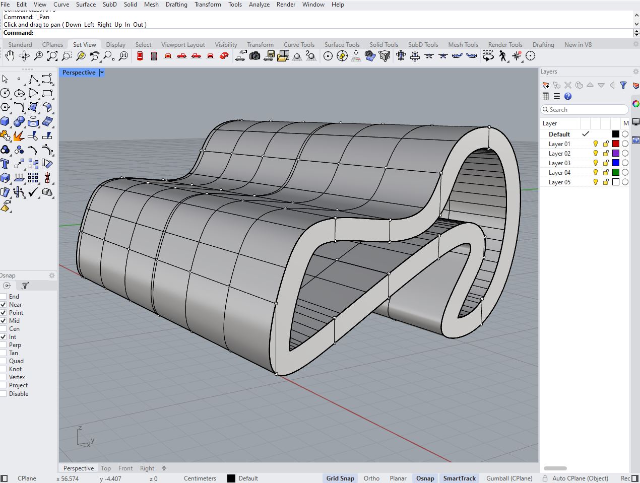
Refine the model by modifying control points and scaling elements proportionally. Verify ergonomic relationships such as seat height, backrest angle, and structural stability. Use Gumball and Control Points tools for precise adjustments.
Organize layers and name critical curves and surfaces clearly. Ensure that the geometry is clean and free of duplicate lines. This preparation allows a smooth transition into Grasshopper for parametric control.
Open Grasshopper and reference the base curves from Rhino. Create numeric sliders to control parameters such as seat height, width, backrest angle, and leg spacing. Connect sliders to transformation components like Move, Scale, and Rotate.
Build relationships between components using mathematical expressions and geometric constraints. Ensure that when one parameter changes, the entire chair adapts proportionally while maintaining structural integrity.
Use control points and graph mappers to adjust the curvature of the seat. This enables ergonomic optimization and aesthetic refinement. Test different curvature intensities dynamically through sliders.
Introduce a thickness parameter to simulate real fabrication constraints. Use Offset Surface or Extrude components to adapt the design according to plywood, MDF, or metal sheet thickness.
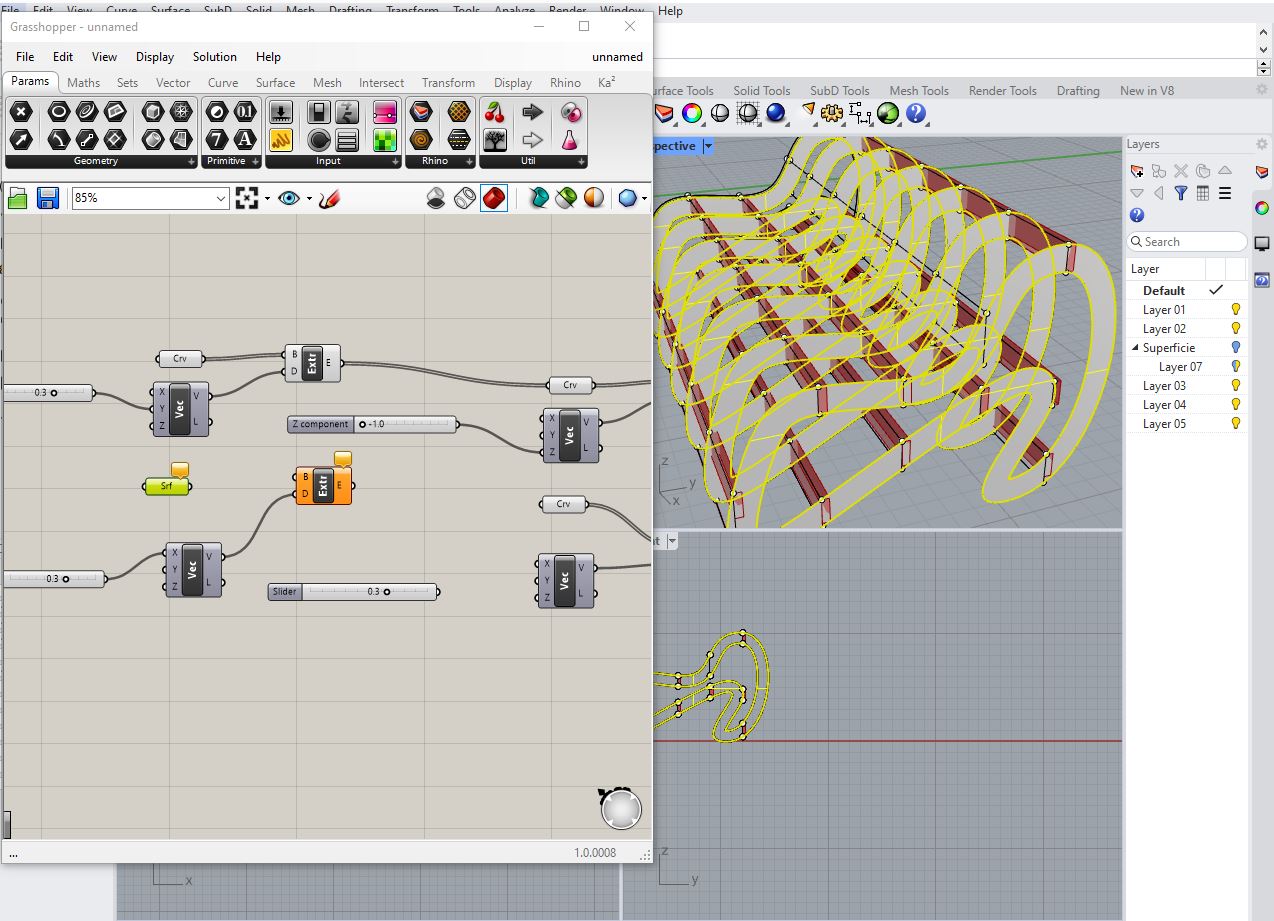
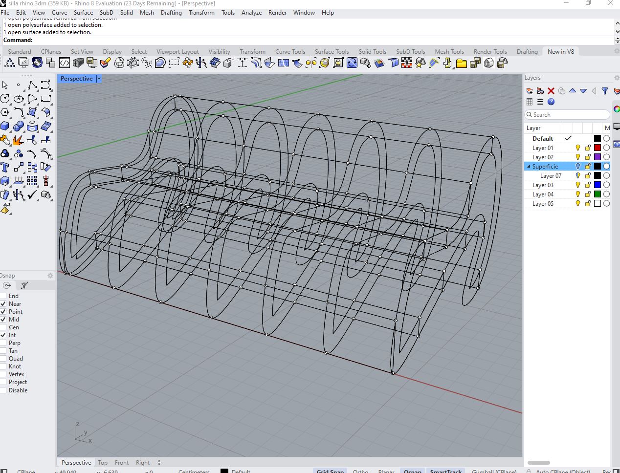
Adjust sliders to generate multiple chair configurations. Evaluate proportions, stability, and visual balance. Capture variations to compare ergonomic and structural performance.
Continue experimenting with parameter combinations to explore alternative aesthetics and functional improvements. This stage highlights the flexibility of parametric modeling.
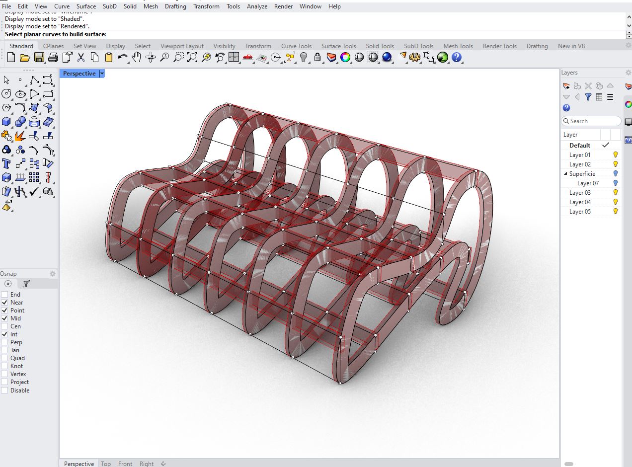
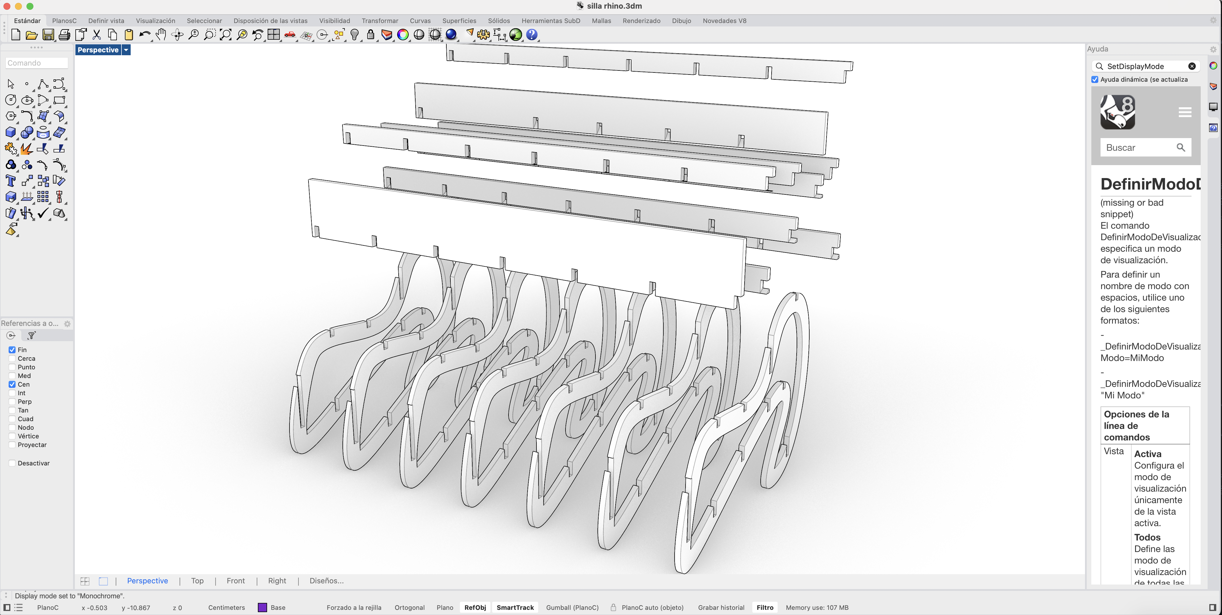
Once the optimal configuration is selected, bake the geometry into Rhino. Check for closed polysurfaces and export the file in formats suitable for CNC cutting, laser cutting, or other digital fabrication methods.
Flatten parts if needed, add tolerances for press-fit joints, and organize components efficiently within material sheets. Verify alignment and toolpath considerations before fabrication.
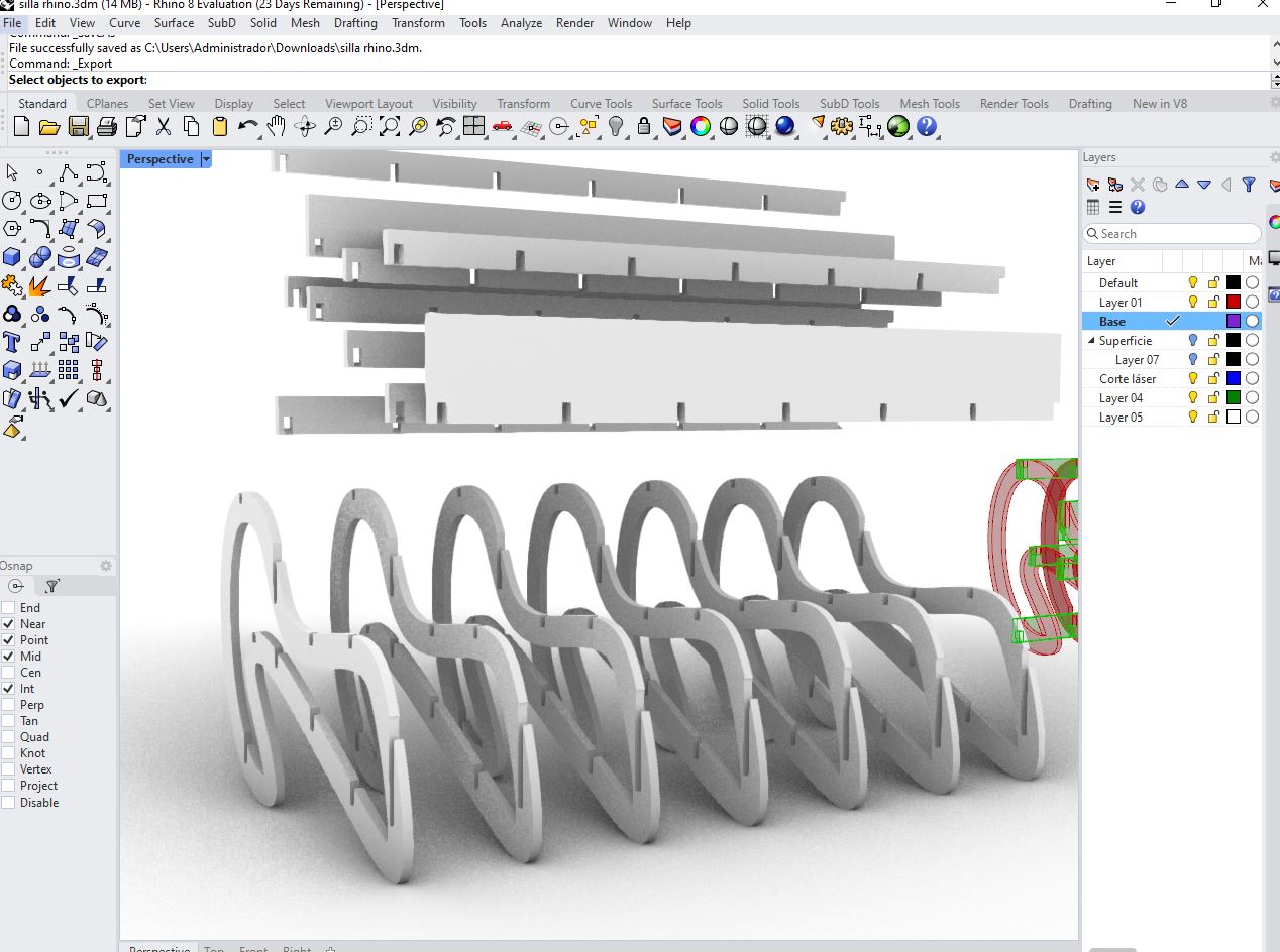
Export the final parametric chair model and generate documentation including dimensions, material specifications, and assembly diagrams. The design is now ready for production and iterative improvement.
| Software | Ease of Use | Accessibility | Cost | Compatibility | Collaborative Work |
|---|---|---|---|---|---|
| GIMP | Medium | High | High | High | Low |
| MyPaint | High | High | High | Medium | Low |
| Inkscape | Medium | High | High | High | Low |
| CorelDRAW | Medium | Medium | Low | High | Low |
| Tinkercad | High | High | High | Medium | Medium |
| Fusion 360 | Medium | Medium | Medium | High | Medium |
| Blender | Low | High | High | Medium | Low |
| Onshape | Medium | High | Medium | High | High |
| Text to CAD | High | Medium | Medium | Low | Low |
| DALL·E | High | High | Medium | Low | Low |
| After Effects | Low | Medium | Low | High | Low |
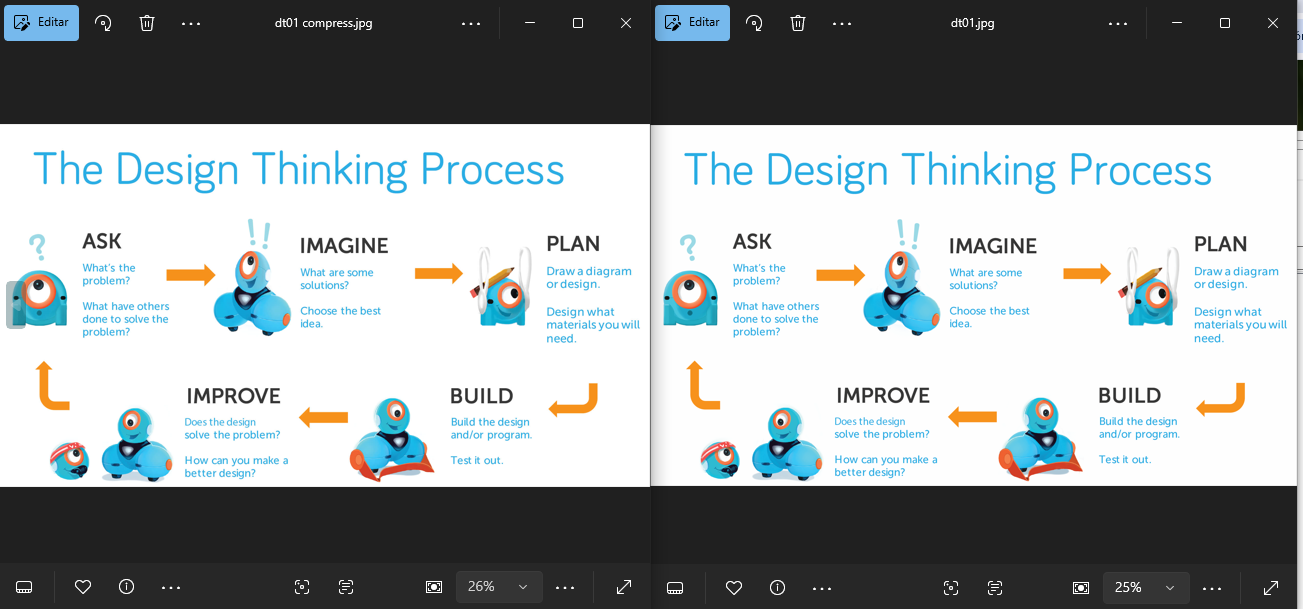
Efficient image compression is essential in Fab Academy documentation to ensure fast-loading web pages while preserving technical clarity. The selected workflow prioritizes accessibility, reproducibility, and minimal quality loss.
TinyPNG is a popular online tool that compresses PNG and JPG images using smart lossy compression techniques. It reduces file size while preserving visual quality, making it ideal for web optimization.
TinyPNG uses intelligent algorithms to selectively reduce the number of colors in an image, which significantly decreases file size without noticeable quality loss.
Image compression is the process of reducing the file size of an image while maintaining acceptable visual quality. It is essential for improving website performance, saving storage space, and optimizing data transfer.
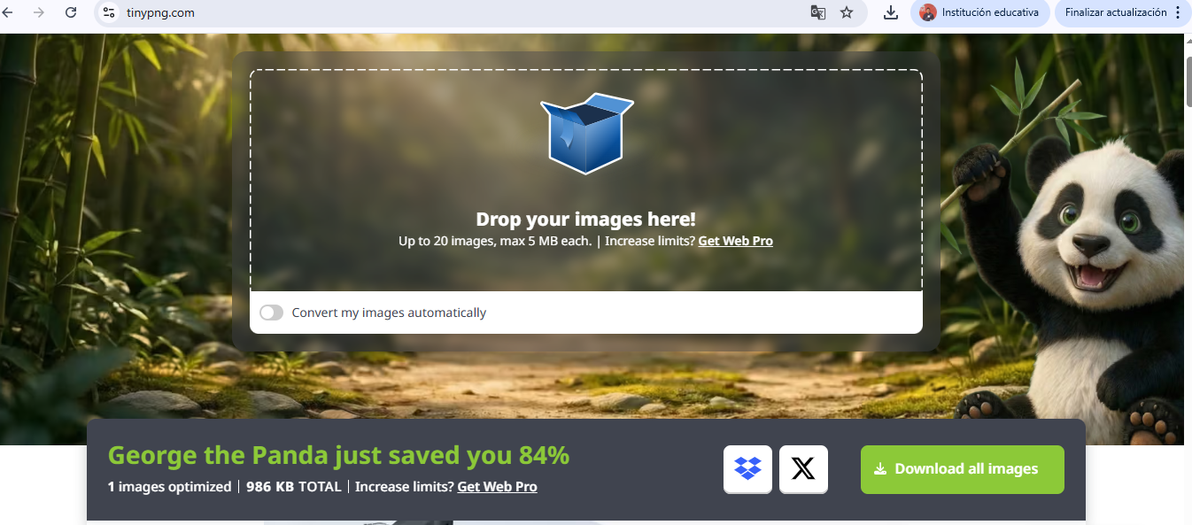
Original image: 1.152 MB
Compressed image: 189 KB
➜ Size reduction: ~84%

The first step consisted in defining the Bill of Materials (BOM) for the assembly station. This stage is critical because it establishes all structural components required for fabrication and ensures modularity and scalability of the system.
The station is composed of:
This definition follows TPS principles by organizing components to support an efficient, ergonomic, and sequential workflow.
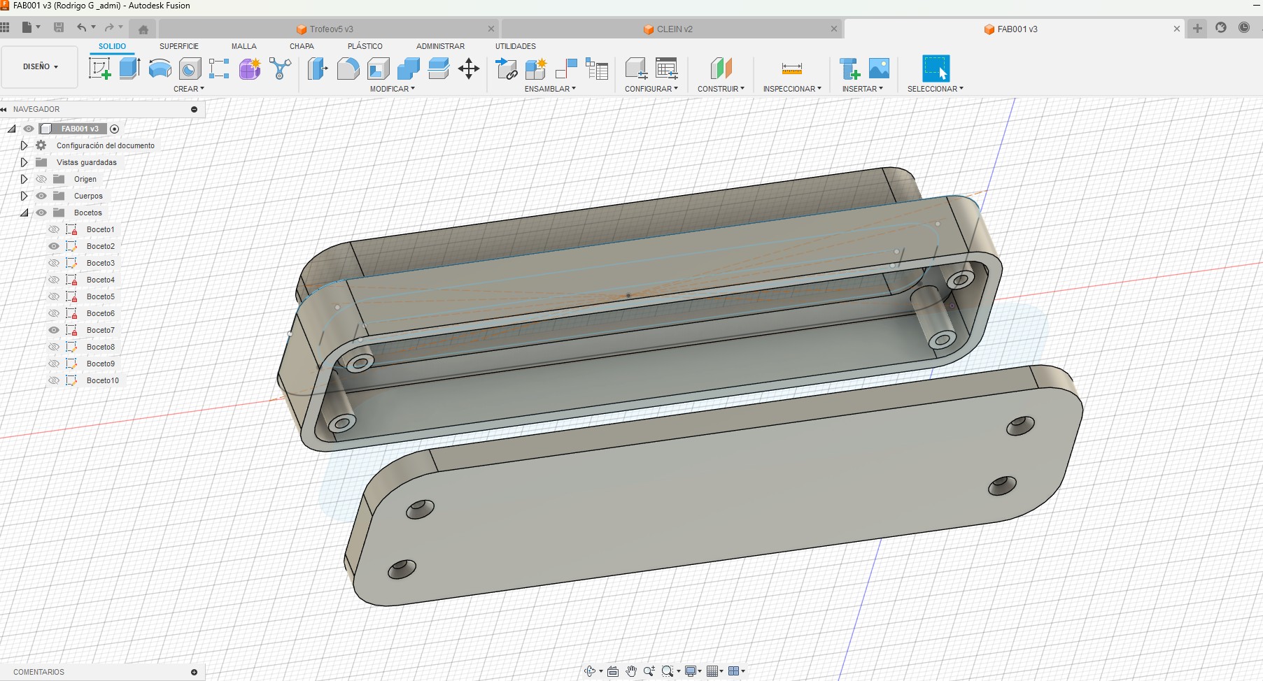
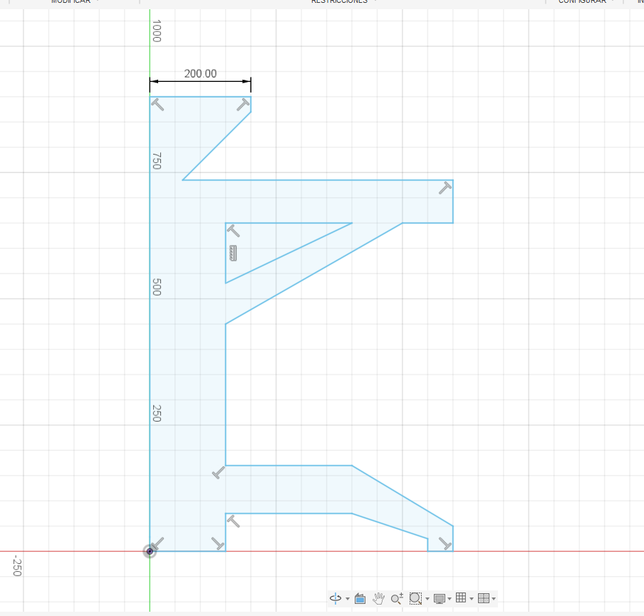
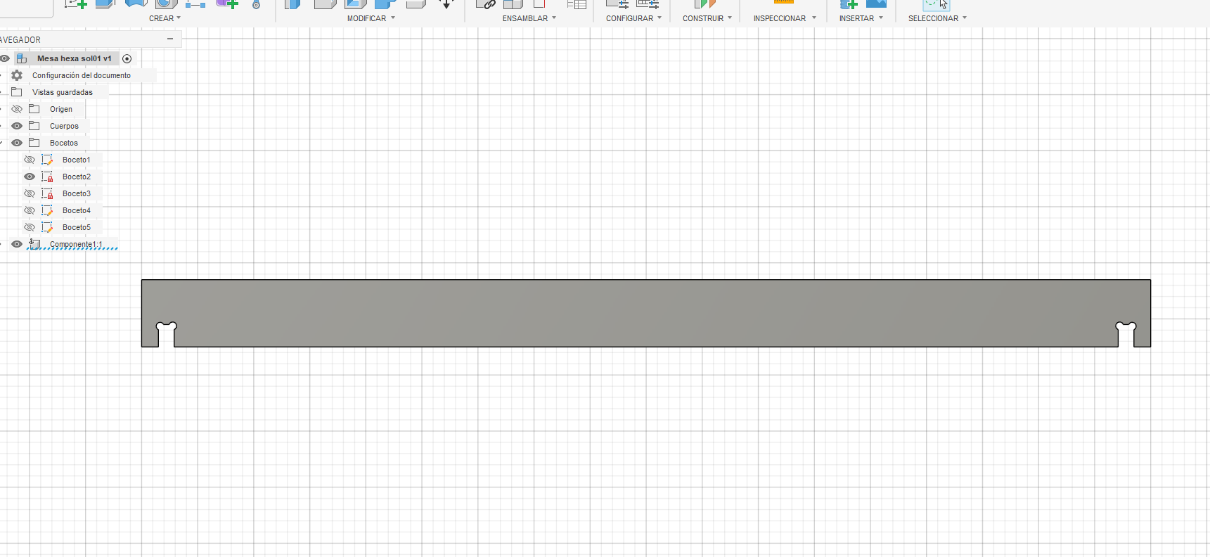
The structure was designed using parametric modeling in Fusion 360. This approach allows easy modification of dimensions and ensures adaptability of the design.
Key parameters such as material thickness, slot dimensions, and tolerances were defined to guarantee proper press-fit assembly.
Parametric modeling process:
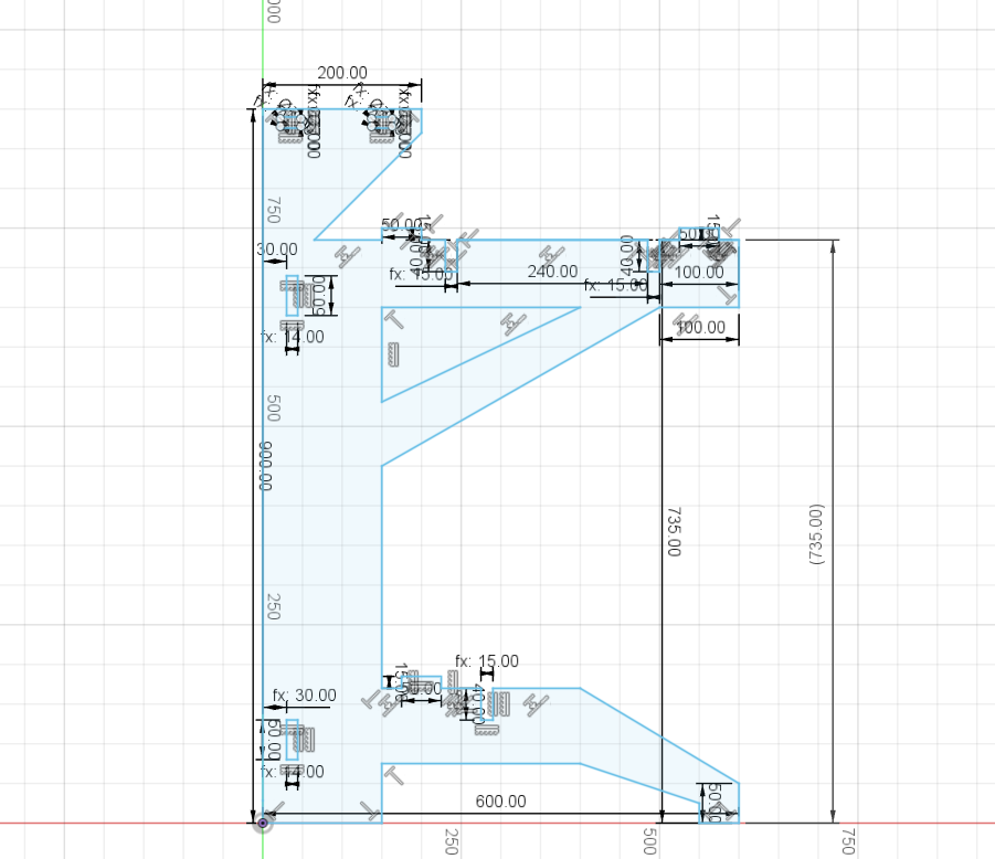
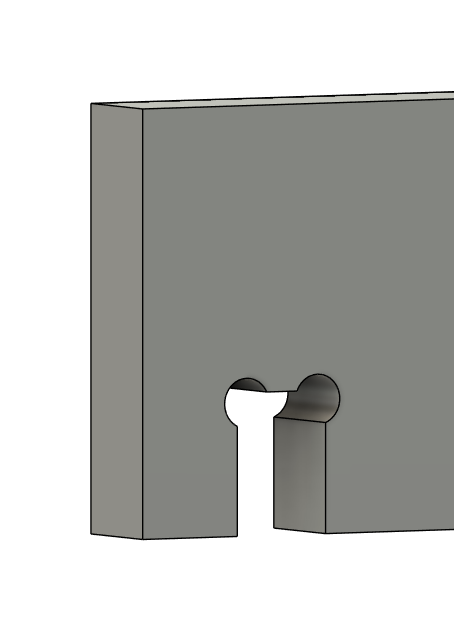
Next, press-fit joints were designed using "dog bone" geometry to compensate for CNC tool radius. This ensures proper fitting between parts.
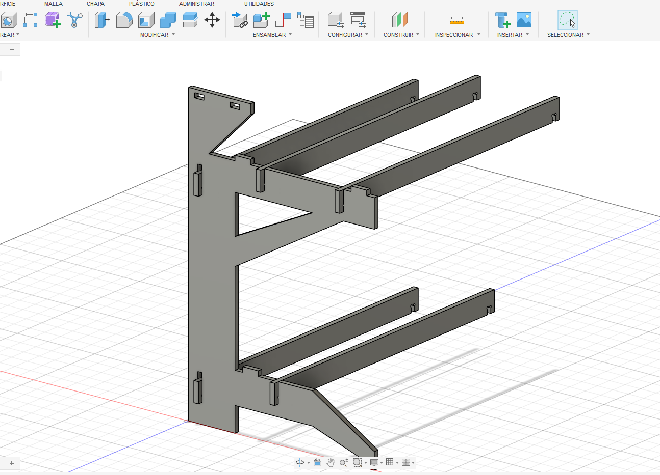
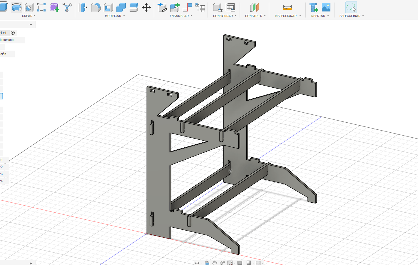
Additionally, lateral panels were modeled in 3D to validate structure, proportions, and assembly logic before fabrication.
Throughout this process, we explored a variety of digital tools across 2D, 3D, and multimedia environments. This allowed us to understand not only how each software works, but also when and why to use them depending on the design and fabrication needs.
Based on the analysis and hands-on experience, for our project we will primarily use Fusion 360 as our main design tool due to its robust parametric modeling, assembly capabilities, and integration with digital fabrication workflows.
Additionally, we will complement this workflow with Rhino, which provides greater flexibility in complex geometries and advanced parametric design. This combination allows us to balance precision, adaptability, and creative exploration.
This learning experience helped us understand that mastering digital fabrication tools is not only about knowing how to use software, but also about developing a logical and strategic design approach. One of the main challenges encountered was adapting to parametric thinking, especially in tools like Fusion 360, where each step must be planned to allow future modifications without breaking the model.
Another challenge was switching between different types of software (2D, 3D, and AI tools), each with its own interface and workflow. This initially caused confusion and inefficiency. However, this was resolved through practice, comparison between tools, and understanding their specific roles within the design process.
We also faced difficulties in achieving precision while maintaining flexibility in the designs. This was addressed by combining parametric CAD tools with more flexible modeling environments like Rhino, allowing us to refine both structure and form.
In conclusion, this process strengthened our ability to select the right tool for each task, integrate multiple technologies, and approach design problems with a more systematic and adaptable mindset.
Regards
✔ Modelled experimental objects and parts of a possible final project in 2D and 3D software
✔ Documented the process using text, images, and screenshots
✔ Compressed image and video files for web documentation
✔ Included original design line and source files