The process
Group assignment — SDS review + test casts
The SDS review and test-cast comparison were run as a team at the VujaDé Lab — I followed online from Kuwait. The full team write-up lives on Notion:
Open the team's Group Assignment on Notion ↗
Individual assignment — designing and casting
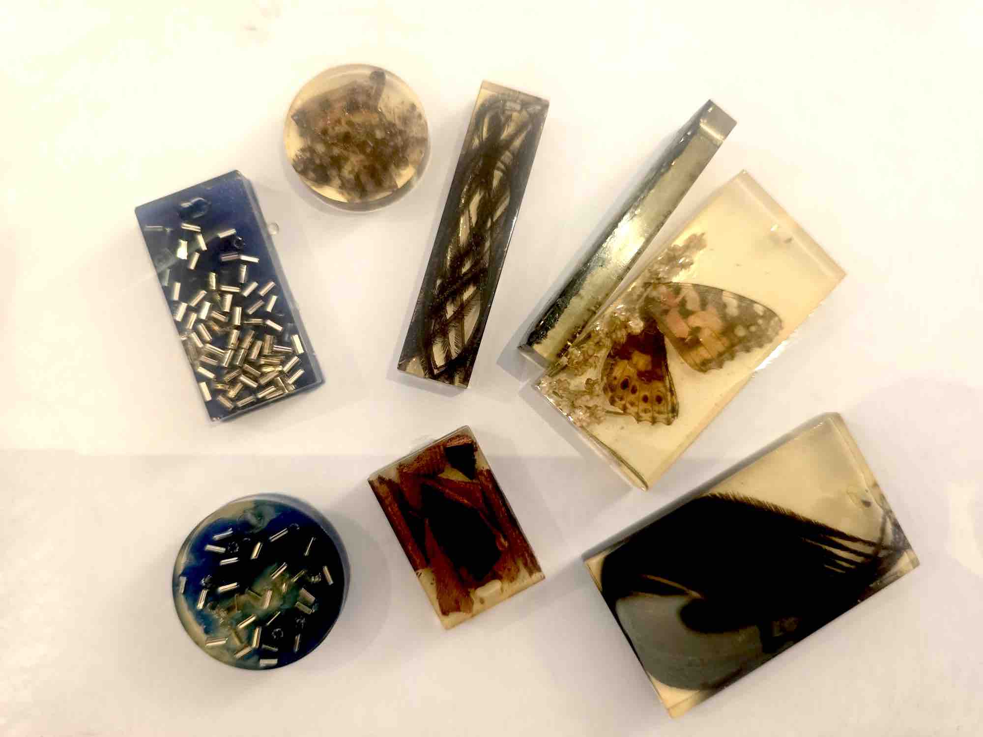
I've had experience casting with resin since 2018 — I made necklaces and used them mainly to keep small cherishable items (more on that in the casting section). I usually used ready-made moulds bought online, so creating my own mould is a new experience I'm looking forward to. I watched over 10 YouTube tutorials on how to model the 3D positive shape and then build the mould around it to cast the positive again.
01: 3D-print mold frame
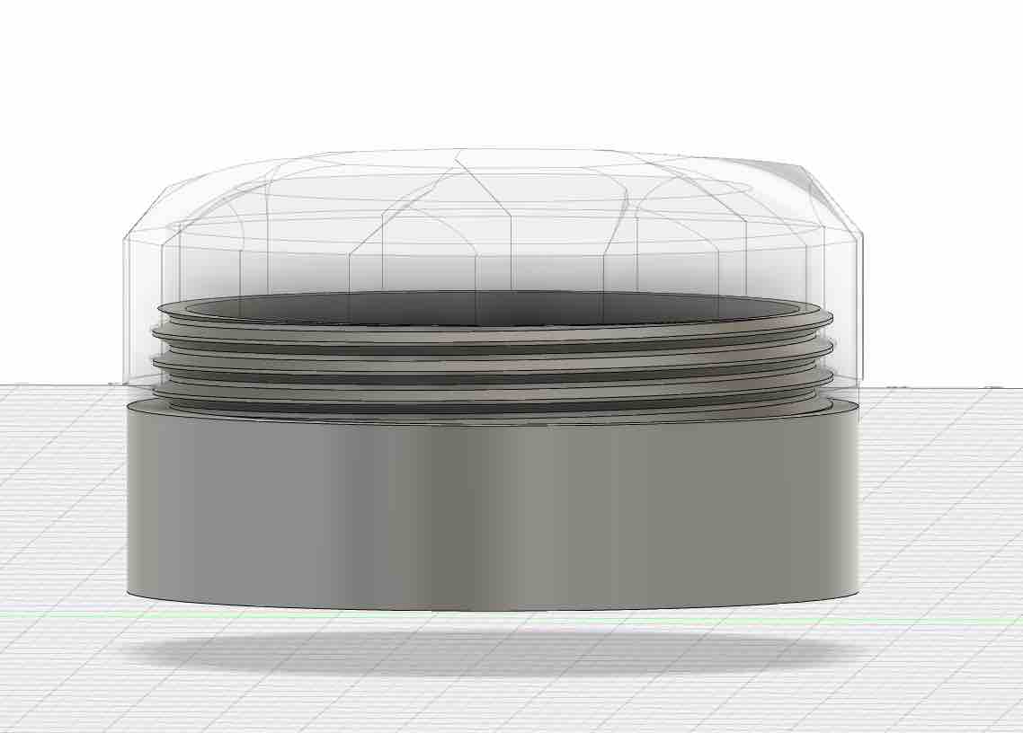
01 | This is the shape of the shoulder clip I'm planning for the final project. It's made of two parts — the bottom part is 3D-printed and holds the PCB, while the top cover will be cast in semi-transparent silicone or resin. I wanted it semi-transparent so the RGB LED — whose function is to display the clip's status (connected, calibrating, or out of the defined baseline) — shines clearly through it. I also added diamond-cut shapes on the cover surface to give the LED a more attractive light distribution.
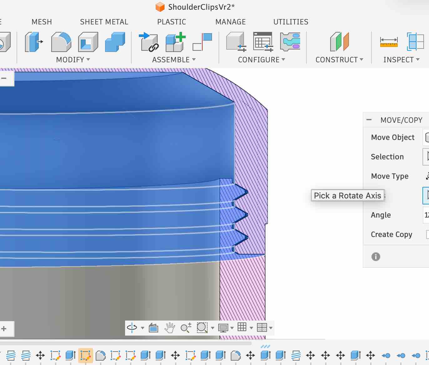
02 | Note that the two parts thread onto each other like a screw — I added a matching thread on the inner mating surface of each part and made sure they fit during the design phase. When I started making the mould I kept one thing in mind: the important features to transfer into the negative mould are both the outside diamond-cut design and the inside thread that lets the cover screw onto the bottom part.
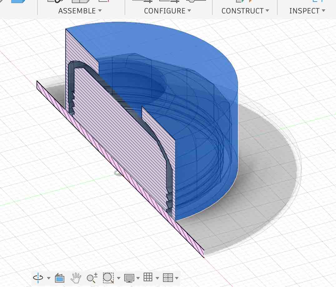
03 | In this design, the new 3D model includes an opening on the top — once the silicone is poured in, it would take the shape of the top cover / lid. I was trying to find a way to open the mould around it. But the more I looked at it, the more I realised the result wouldn't be the negative of the master shape — it would be a positive copy. So I had to rethink the approach.
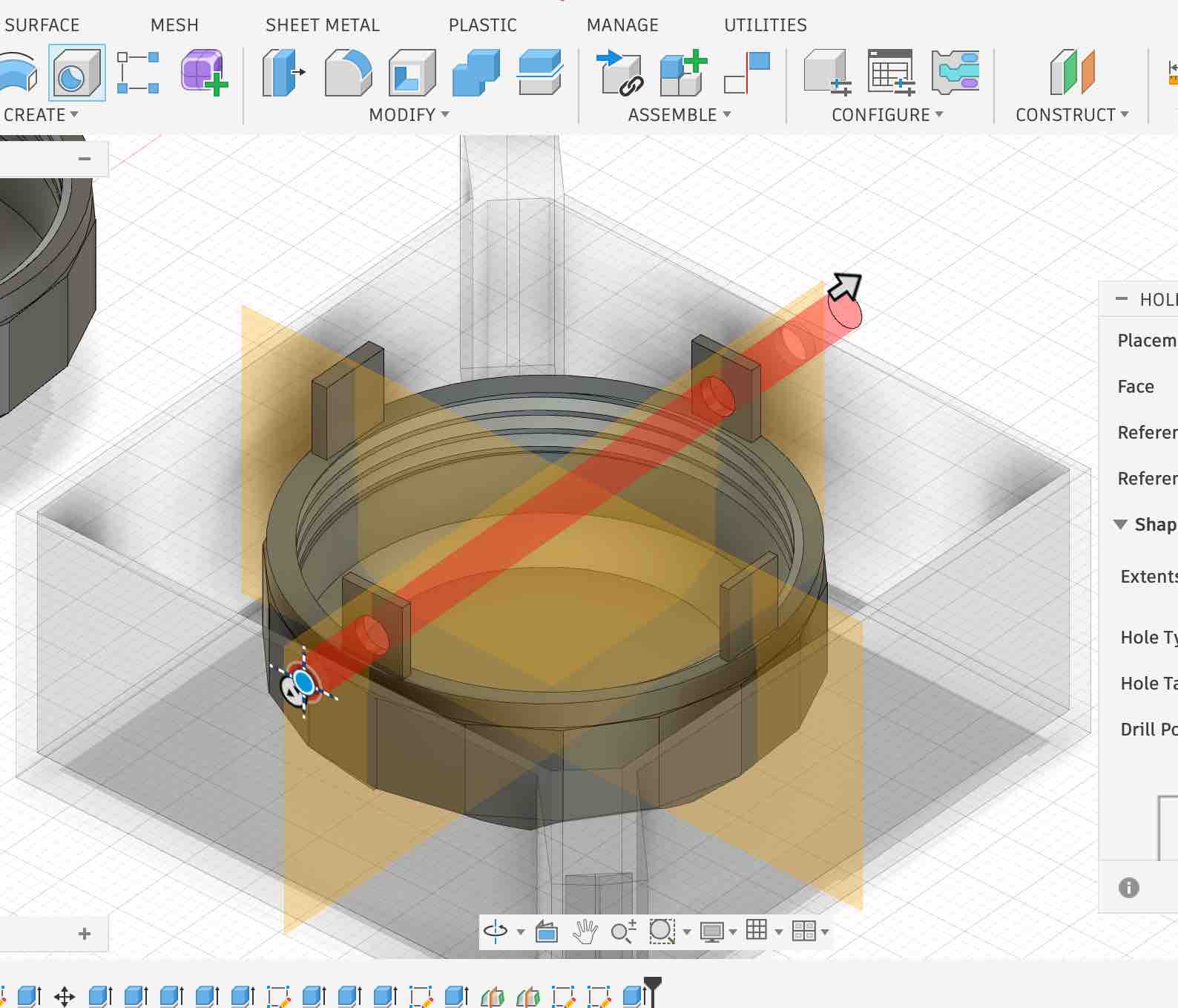
04 | I switched to a different approach: build a frame to hold a silicone mould with the master shape suspended inside it, so the silicone wraps around both the outside and the inside surfaces. The additional holders shown in the picture keep the master shape suspended in the silicone pour. One mistake I noticed here: I should have moved one set of holders higher than the others, so they don't all sit at the same height — I'll explain why in the moulding phase below.
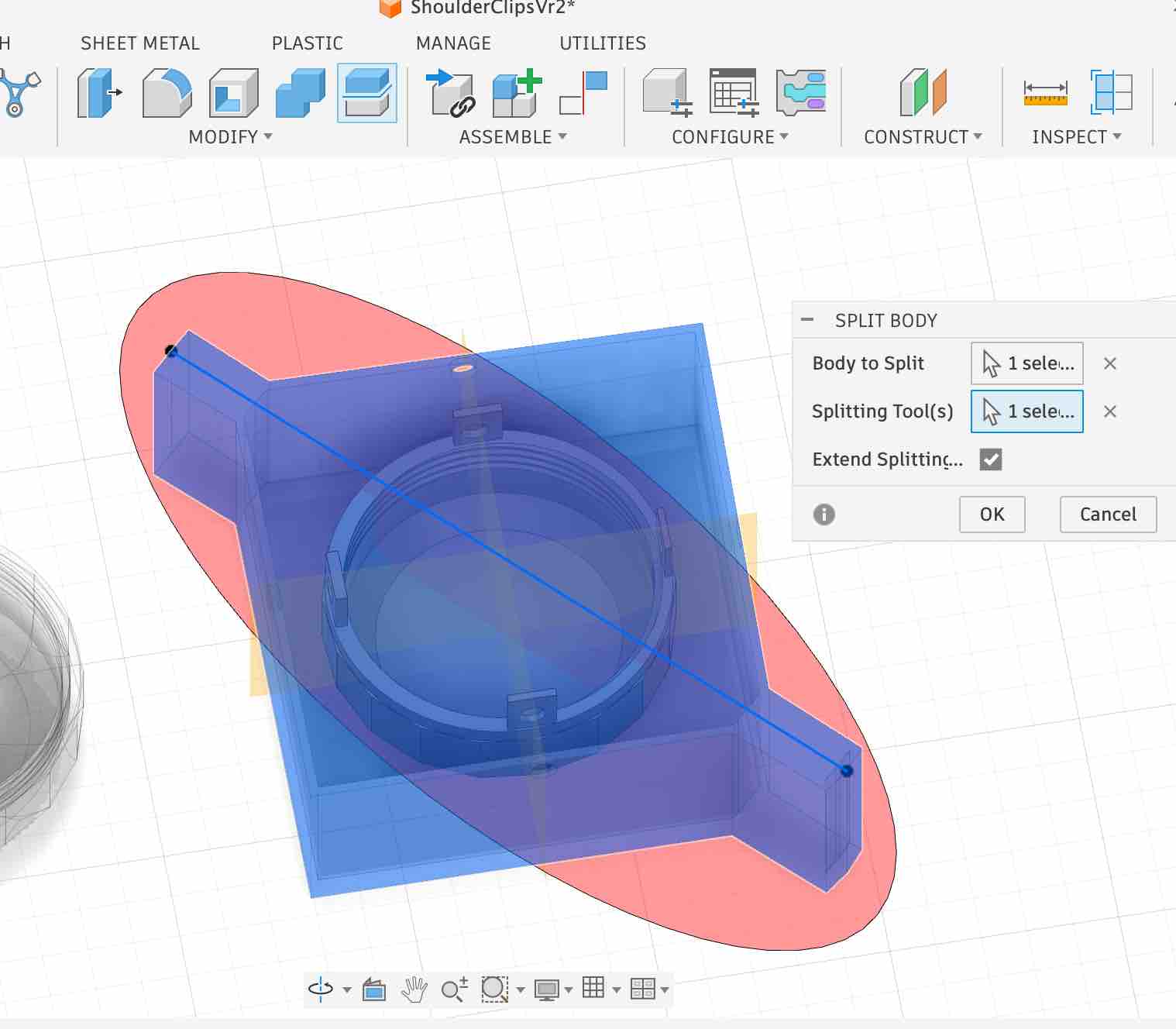
05 | This is where I cut the mould frame diagonally so I can split it open and remove the cured silicone mould later. Making sure the frame stays tight when assembled — so silicone doesn't leak during the pour — is the critical detail here.
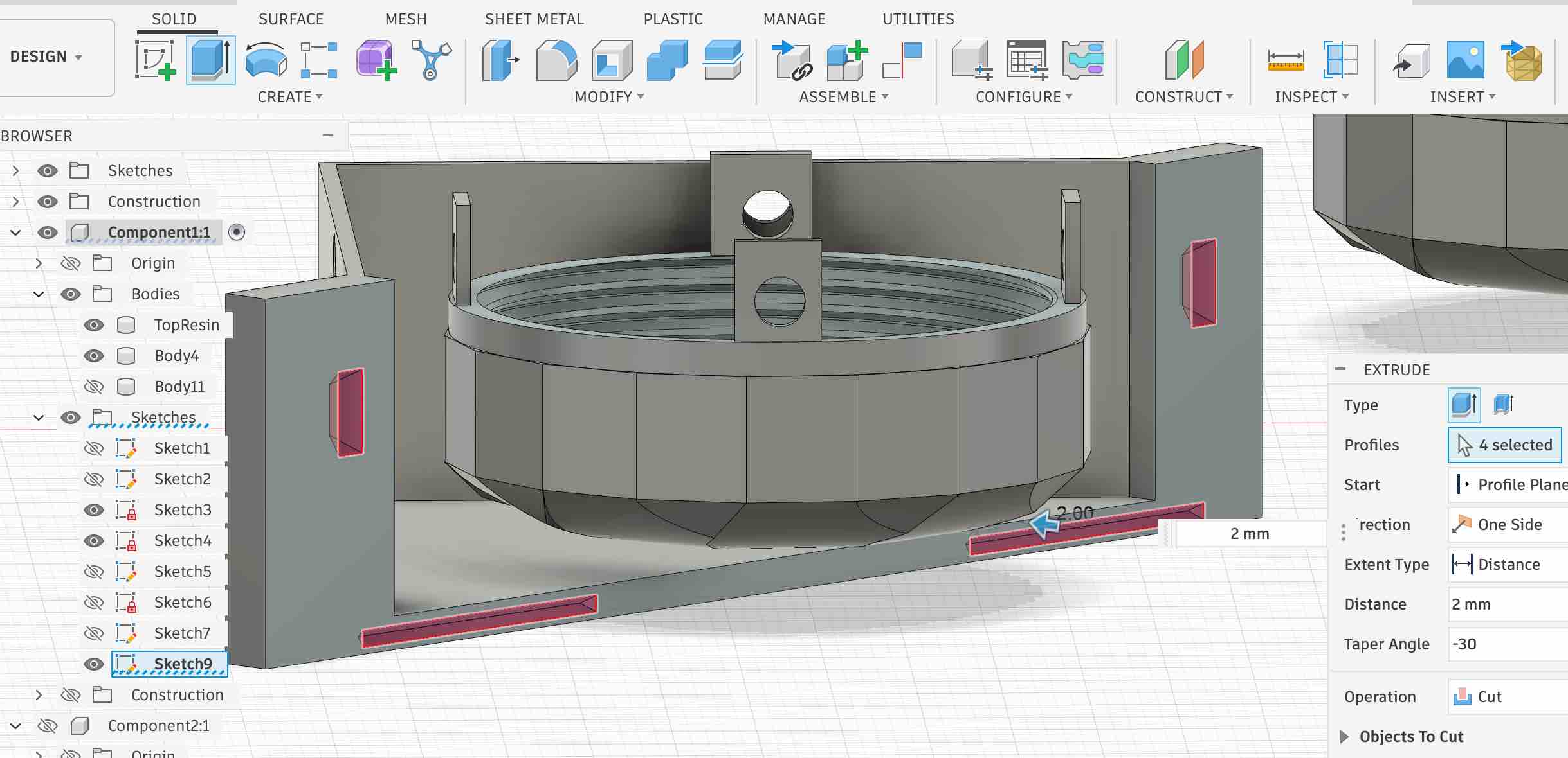
06 | I added alignment pockets on the mating surfaces of the mould frame — negative on one side, positive lead on the other — so the two halves snap together correctly and seal cleanly, stopping the silicone from leaking during the pour.
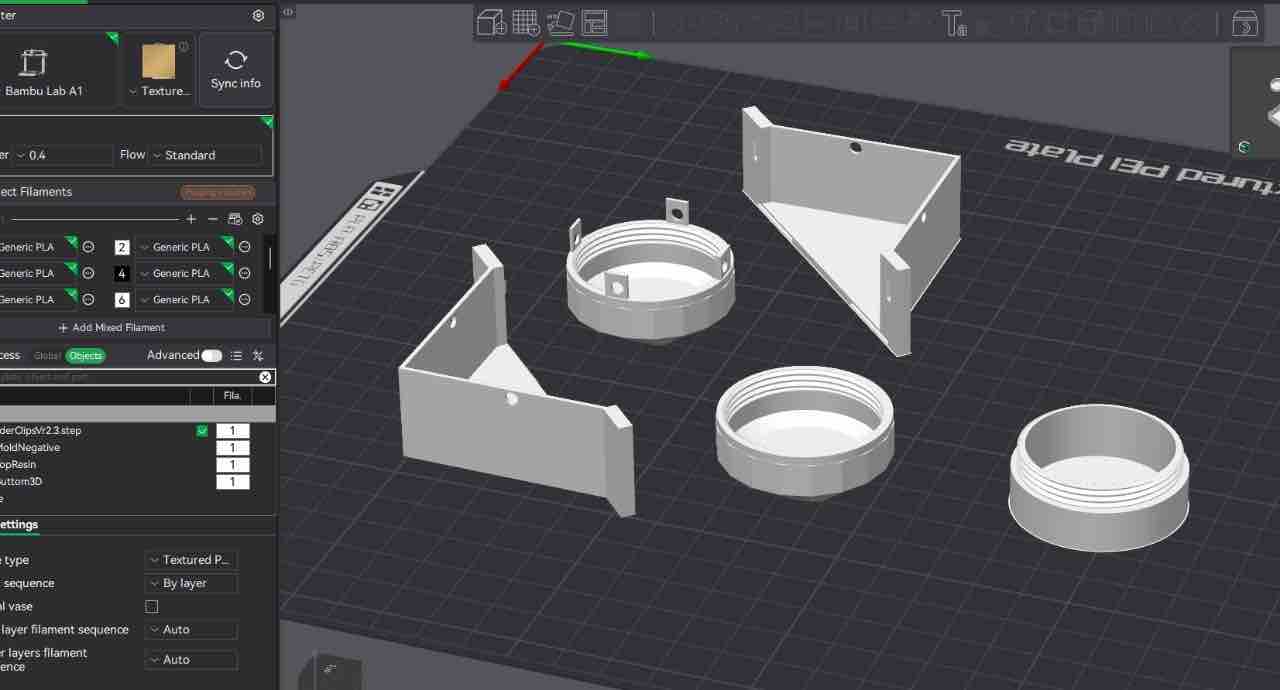
07 | I then printed the parts of the mould frame and the master shapes. Here is the original STEP file.
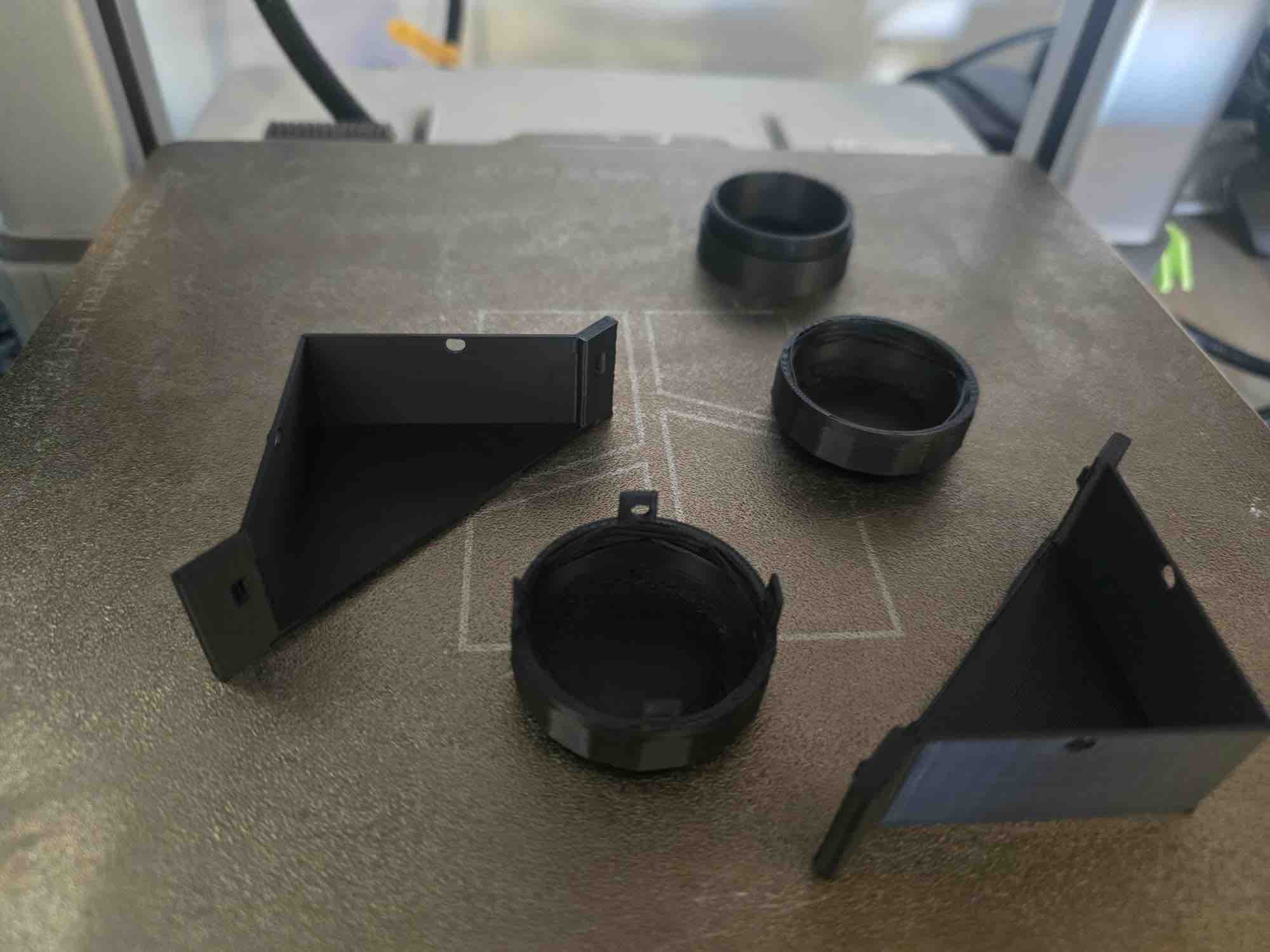
08 | This is the full set of printed parts laid out together — both halves of the mould frame, the alignment lips, and the master shape — ready to dry-fit and check the seal before pouring silicone.
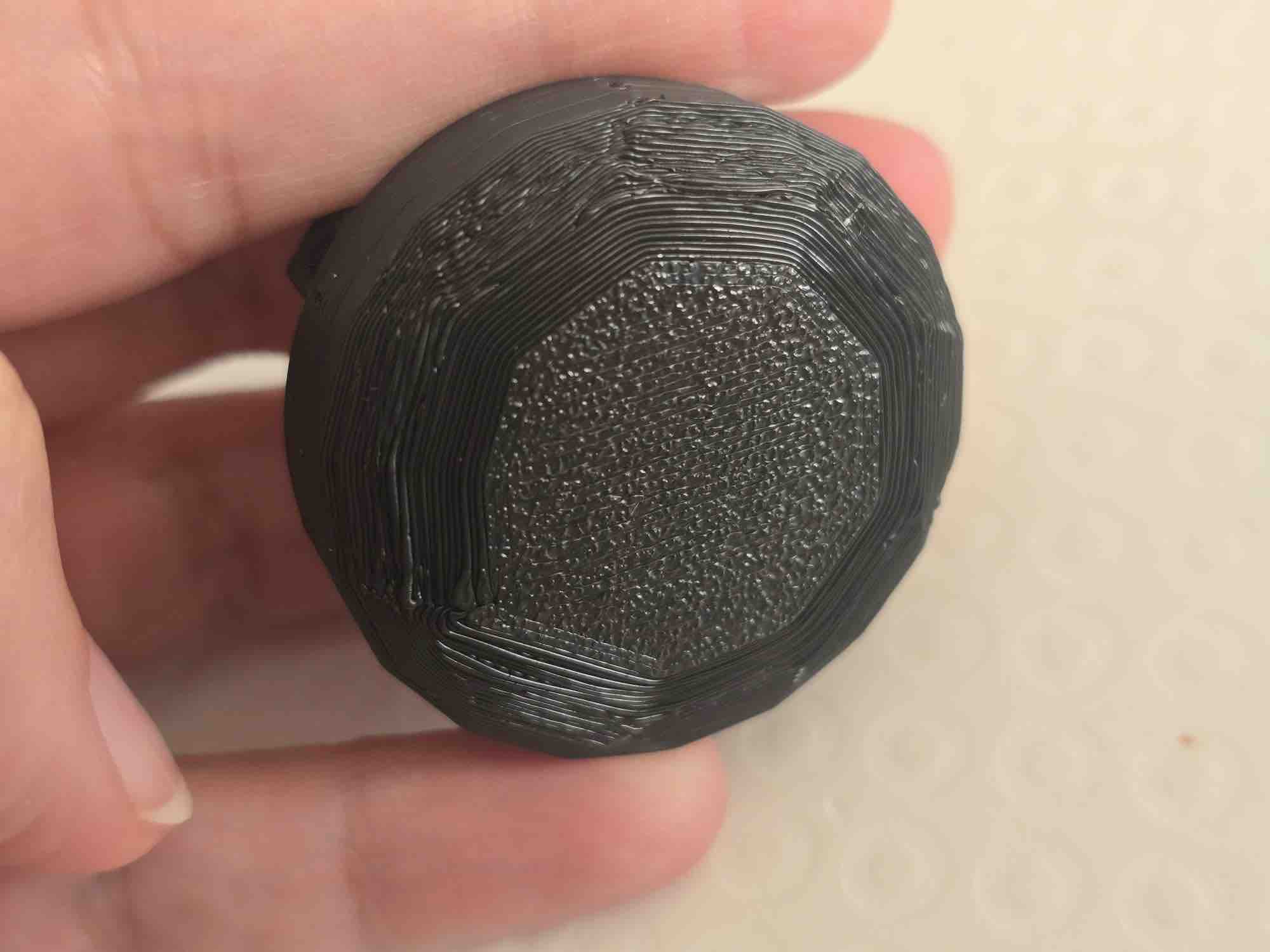
09 | Unfortunately some of the fine details on the master shape didn't print correctly — but I'm running out of time to spend more on the design and reprint phase. I'll use this version now, especially since the silicone cure of the negative mould, followed by the resin cure of the positive cast, will already consume significant time.
- Feedback: I got really confused about what's needed — negative versus positive shapes, and which one ends up as the mould. There are many ways to approach this and the online community shares many techniques; I'm looking forward to trying more of them in future projects. Aisha also did a great job explaining the details of how she's working with moulds and casts, which helped me re-orient.
- Challenge: As usual, time — I want to try everything and there isn't enough time to. I had to focus on what it takes to finish the final-project deliverable, not on exploring every casting technique.
02: Cast the negative (the silicone mould)
For the negative mould I used a two-part silicone with a 1:1 mix ratio, poured around the printed master shape suspended in the frame.
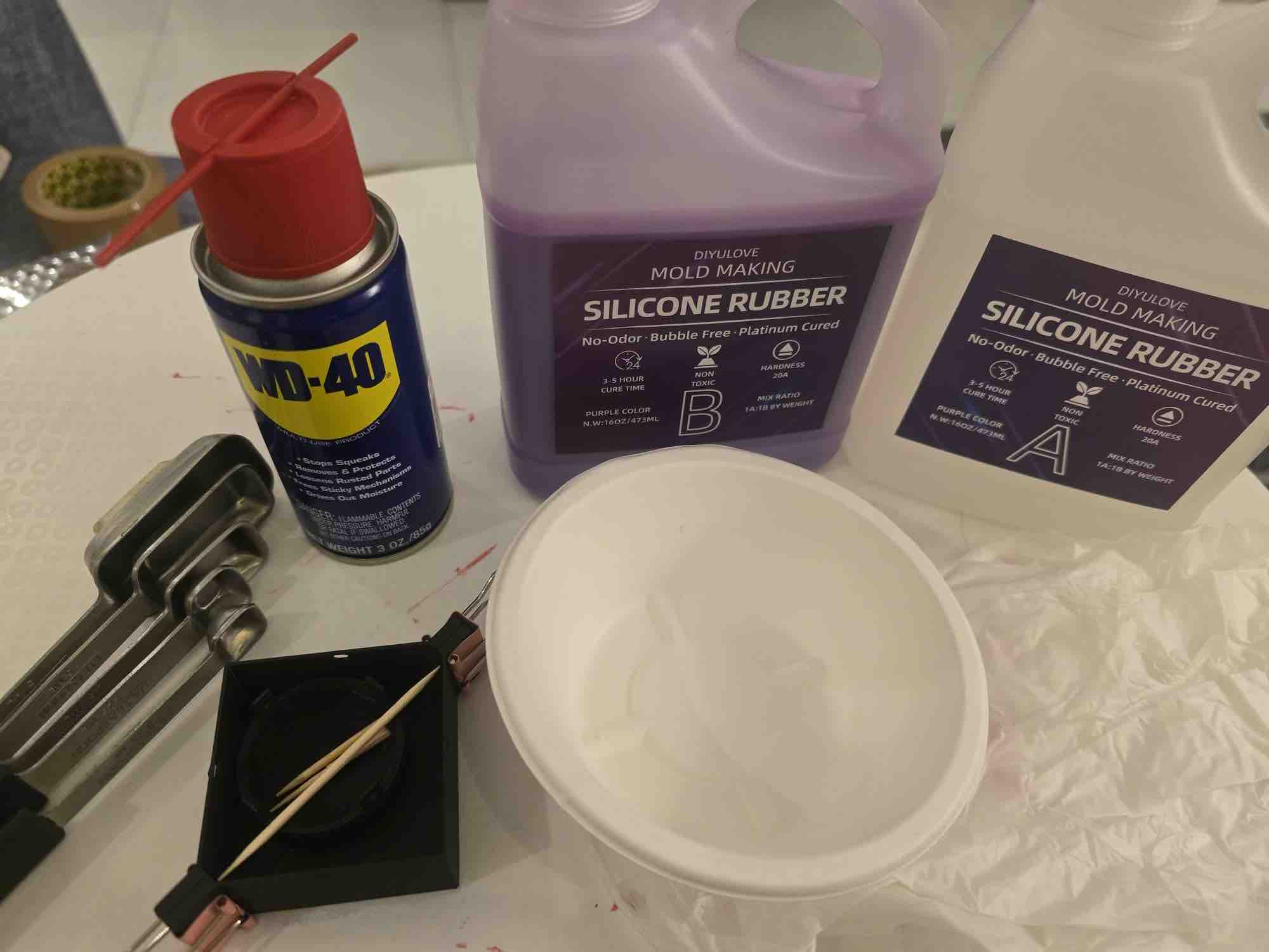
01 | I used the DIYLOVE mould-maker (a two-part silicone mixed at 1A : 1B), and laid out all the tools I'd need: gloves, measuring spoons, a paper cup, and some toothpicks for stirring the mix.
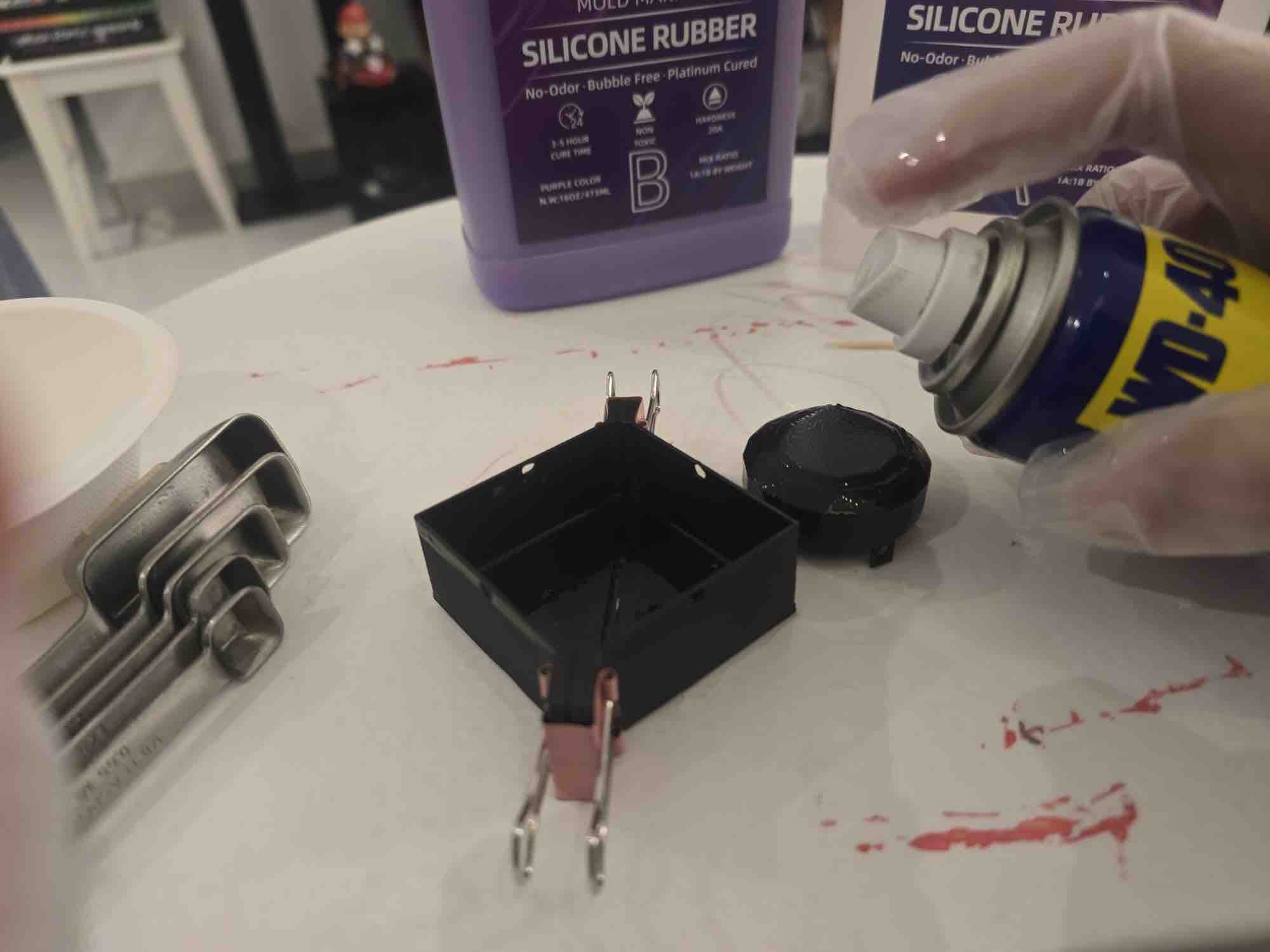
02 | I started by spraying WD-40 as a release agent on the mould frame and the master shape — covering every inner surface to make it easier to remove the silicone mould once it cures.
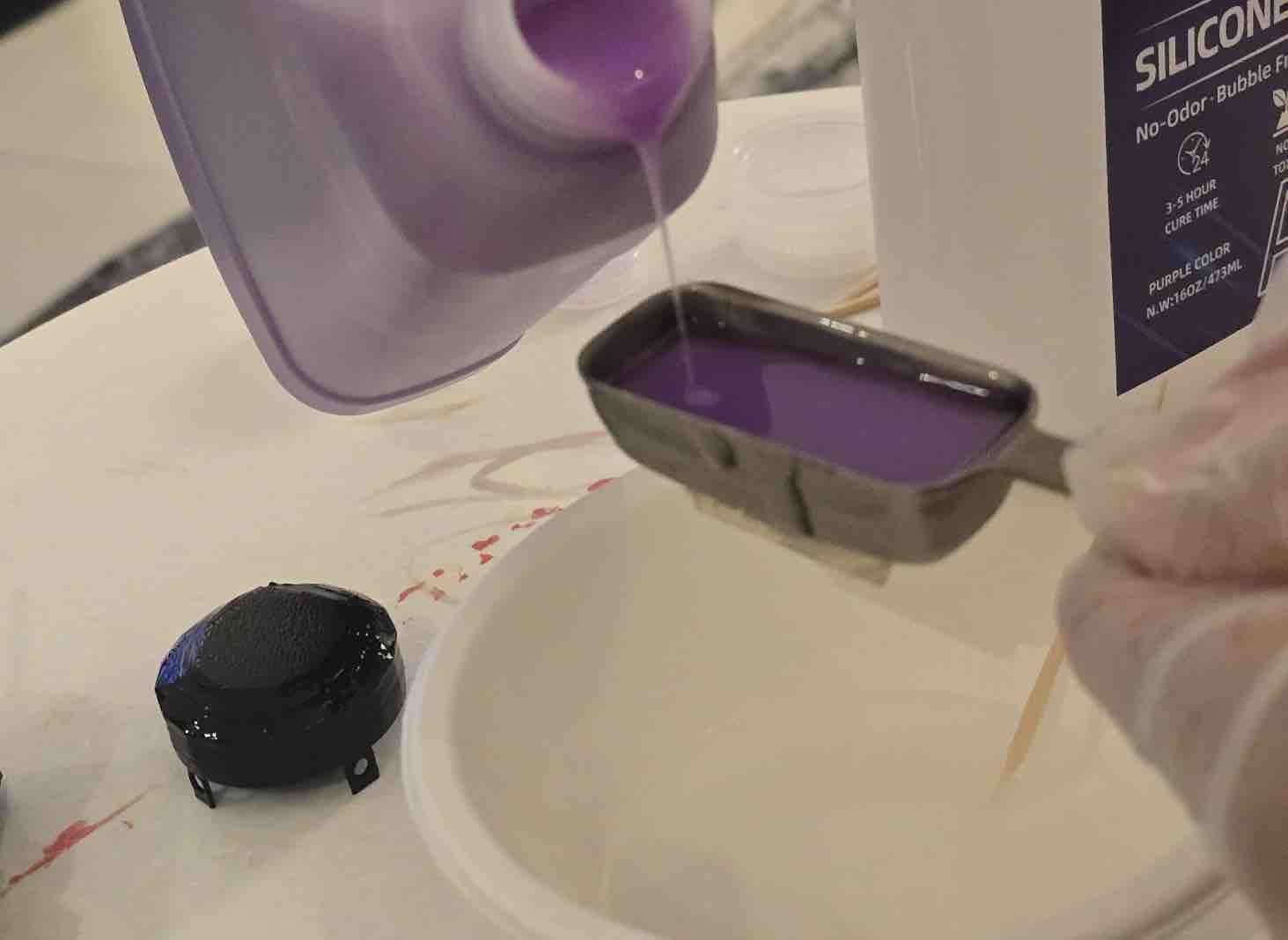
03 | Then I added a spoonful of each silicone (Part A and Part B at a 1:1 ratio) into the paper cup and mixed them thoroughly until the colour was uniform.
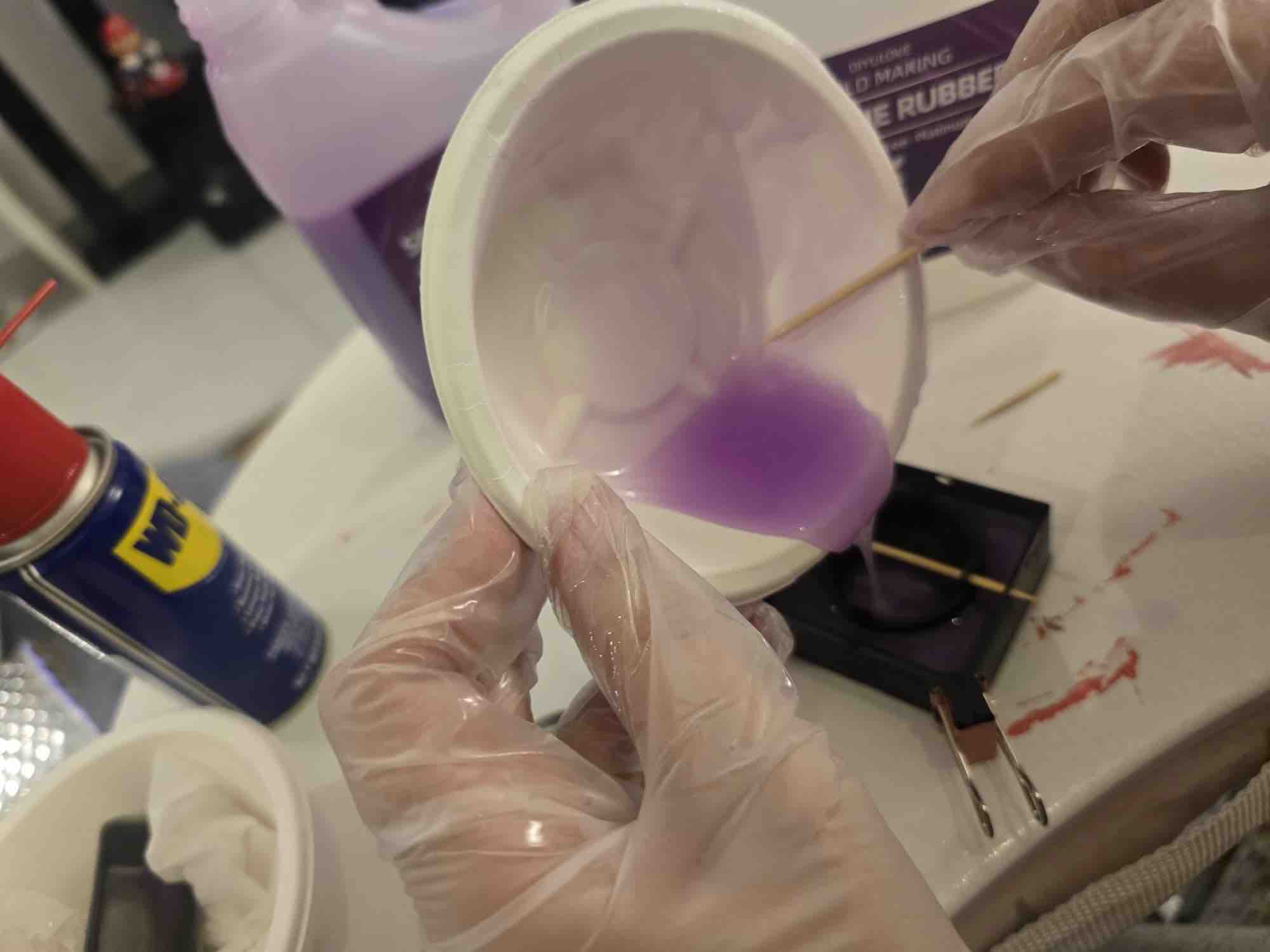
04 | I poured the mix into the mould frame, and once it reached a usable height I placed the positive cover shape inside — using a toothpick to keep it from sinking. Then I kept pouring the mix around and inside the shape until the top edges were fully covered with silicone.
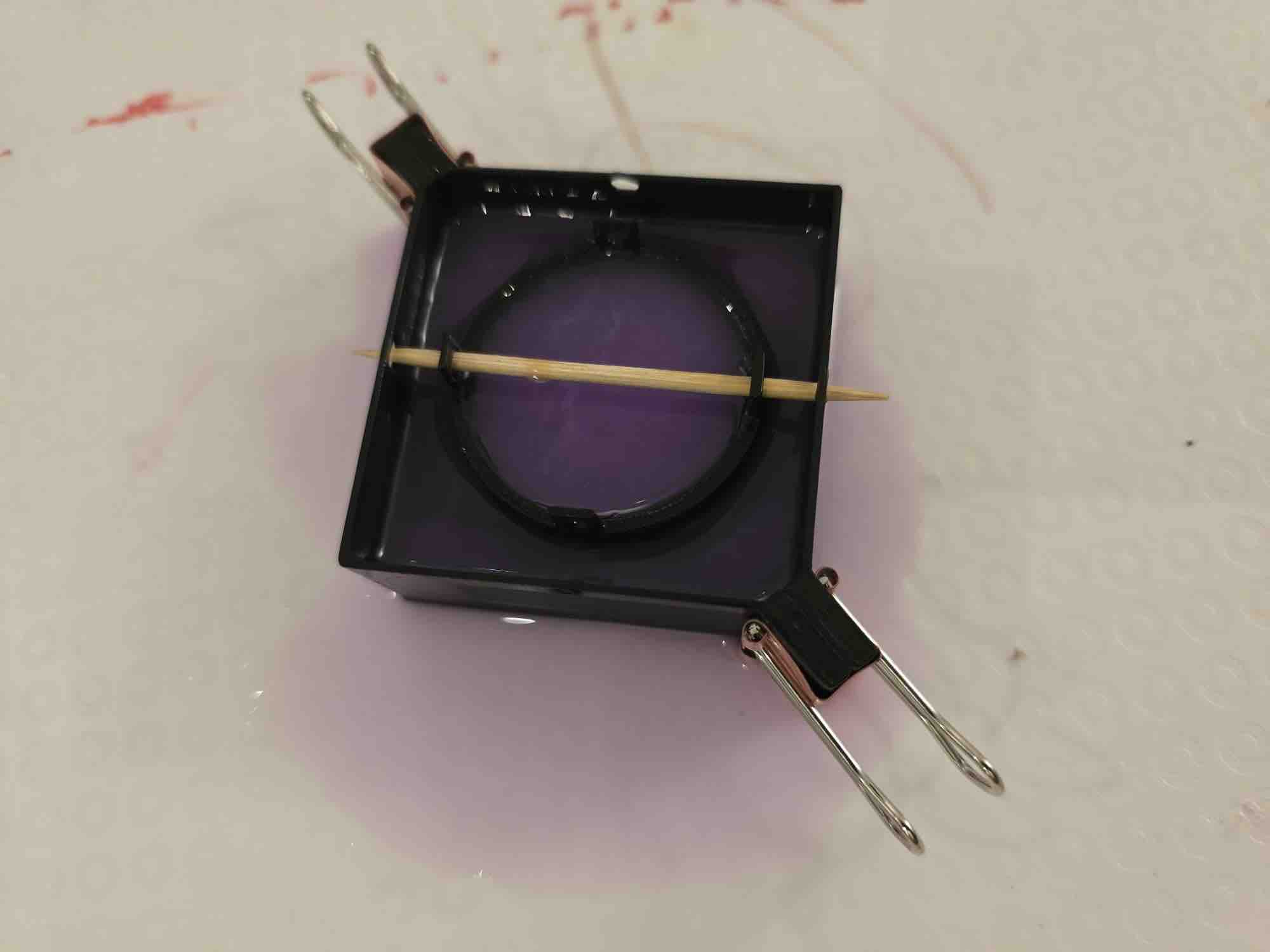
05 | Once done, I removed all the other items, cleaned the tools, set the mould frame aside, and set a 1-hour timer to check on the cure. After an hour I noticed a leak from the mould frame — but I decided to leave it as the silicone had already started to set and wouldn't leak much more. I lost some material, but given the schedule (still ahead of me: the resin pour and cure of the positive part), I decided not to repeat the pour and kept the current mould.
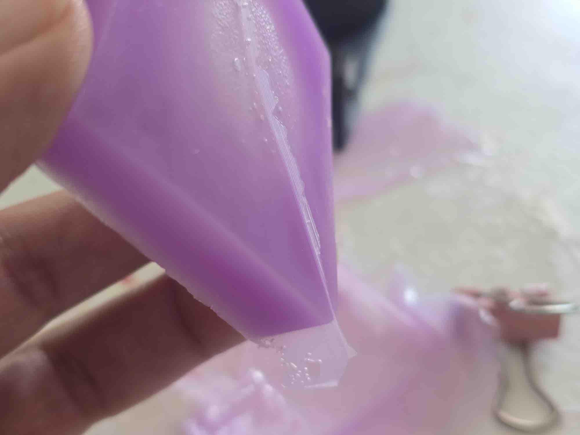
06 | After removing the cured silicone mould from the frame, I was able to identify the areas where the silicone had leaked through. Those are now marked as fixes for the next spiral of the design — most likely a wider lip-and-groove seal between the frame halves.
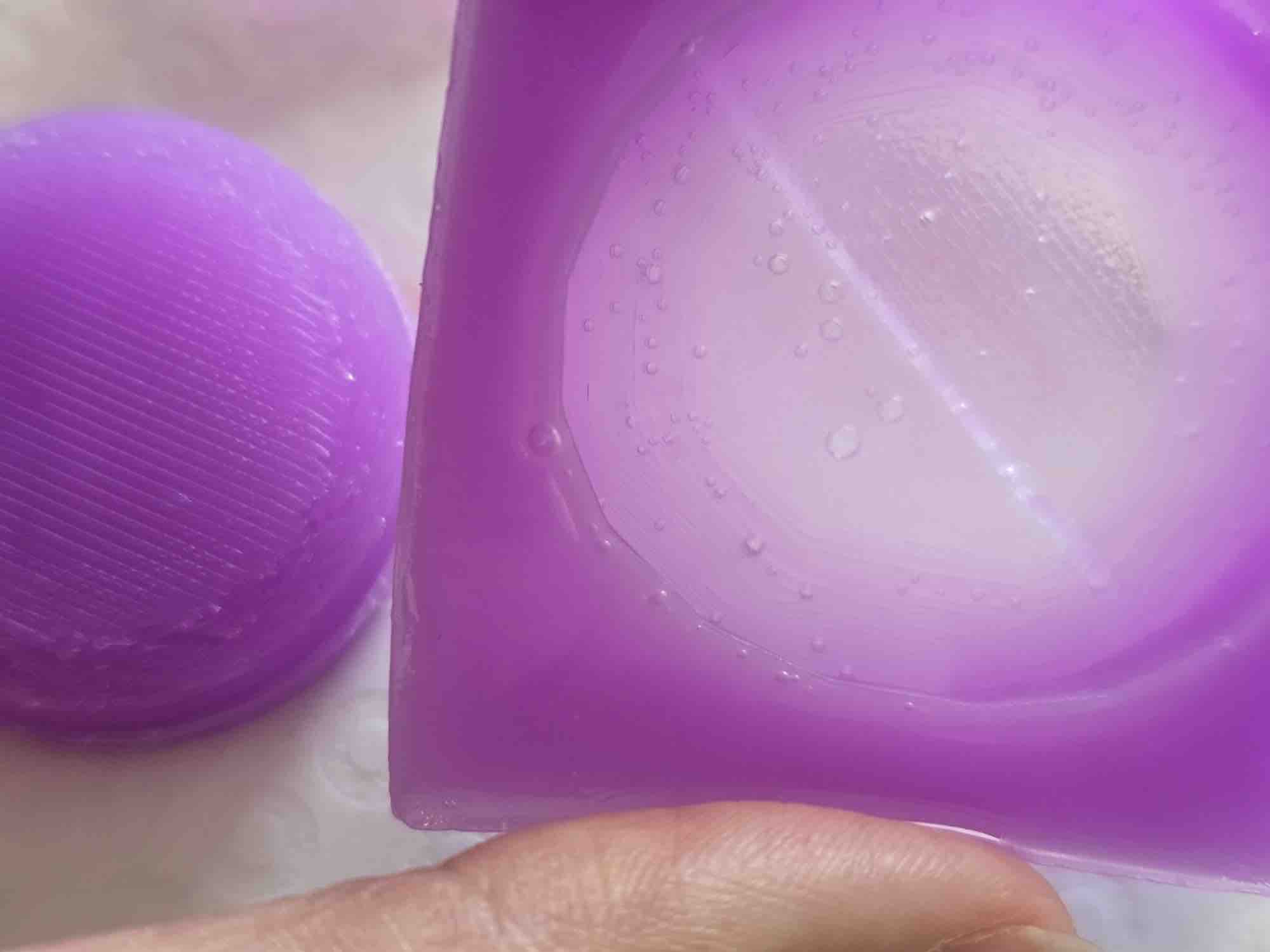
07 | Another thing to fix on the next attempt: make the mould deeper so I don't risk damaging the cast when I demould it. The negative patterns from the master have transferred beautifully into the silicone. I can also see some bubbles in the silicone — they probably mean I needed to stir in one direction only (instead of swirling), or use heat (e.g. a quick blowtorch pass) to bring the trapped air to the surface before the silicone set.
- Feedback: I was upset that the mould frame leaked, and after looking at the cured silicone mould I noticed I couldn't cut and use it the way I'd originally planned. The frame seal — the alignment-pocket detail from §01 step 06 — is where the seal failed, and that's the part I'd reinforce next time.
- Challenge: Working to the schedule is a totally different mindset from working to perfect the task — and it's one of the skills I've practised most during my Fab Academy journey. The decision-making wasn't easy: I wanted better outputs, better results, especially when I compare against the work of other students around the world. But mastering the skill by making mistakes and thinking about how to solve and avoid them is more important than getting things right the first time.
03: Cast the final part (UV resin positive)
For the final positive cast I'm using a UV-cure resin poured into the silicone mould from §02. The goal is a transparent (or semi-transparent) top cover for the clip, with a diamond-cut geometry so the RGB LED status colour displays beautifully through the surface.
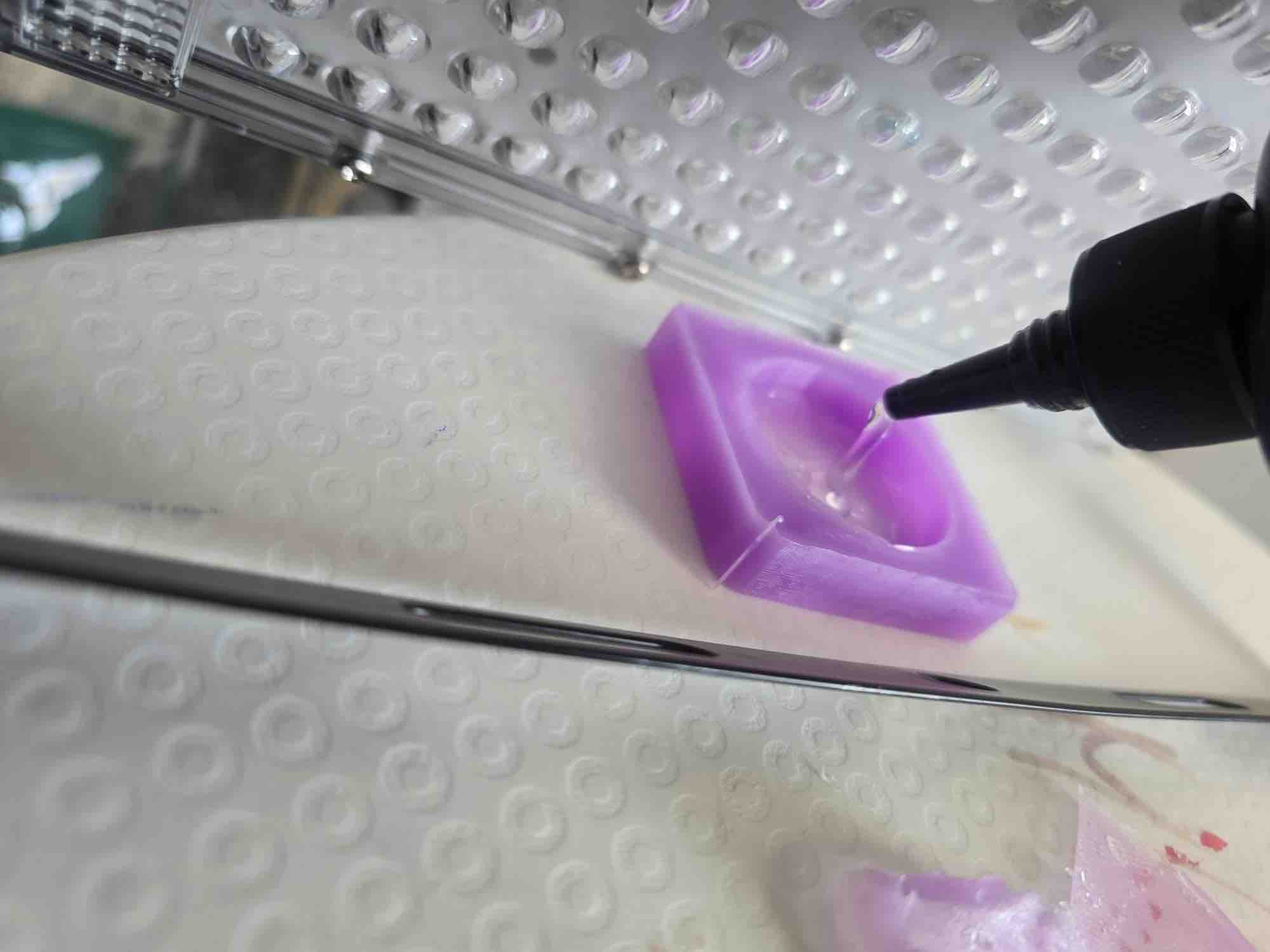
01 | I started by pouring the UV resin in small quantities and tilting it across the mould to create thin layers — thin layers cure faster under the UV lamp than a single thick pour, and they let me build the part up gradually before closing the second half of the mould on top.
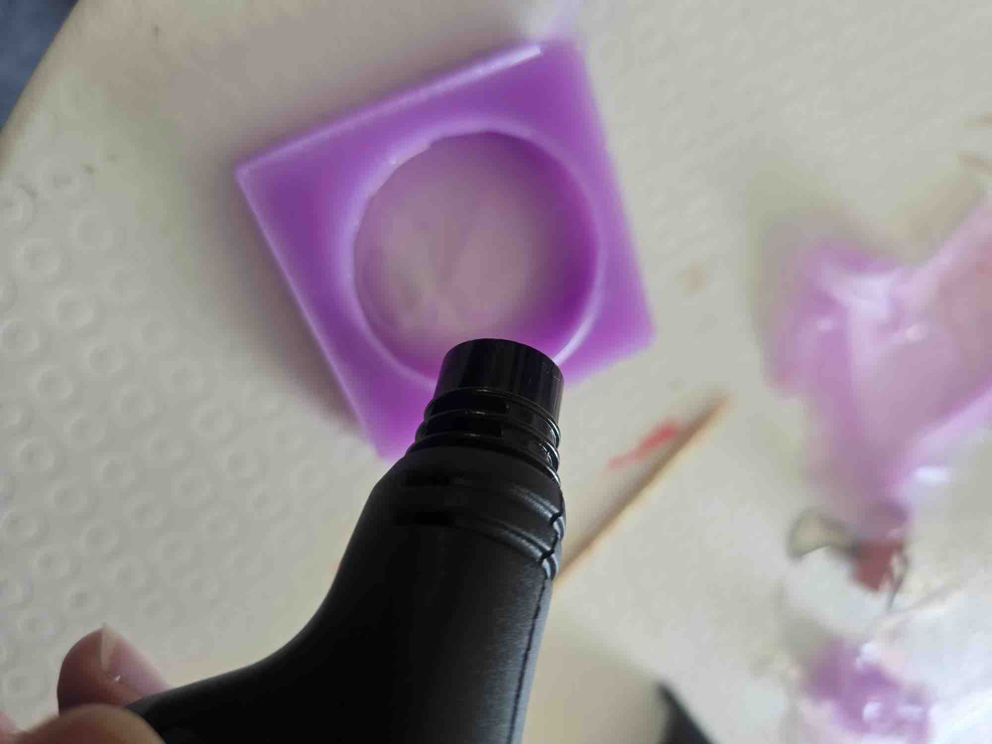
02 | I also used a blue-flame torch over the resin to drive any trapped bubbles to the surface — but had to use it carefully and only for less than a second at a time. The flame is hot enough to scorch the resin or melt the silicone mould if held too long.
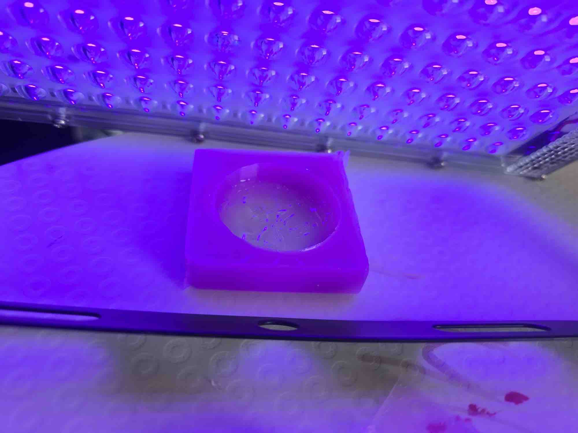
03 | I then left the first thin layer to cure under the UV light for 15 minutes before pouring the next layer.
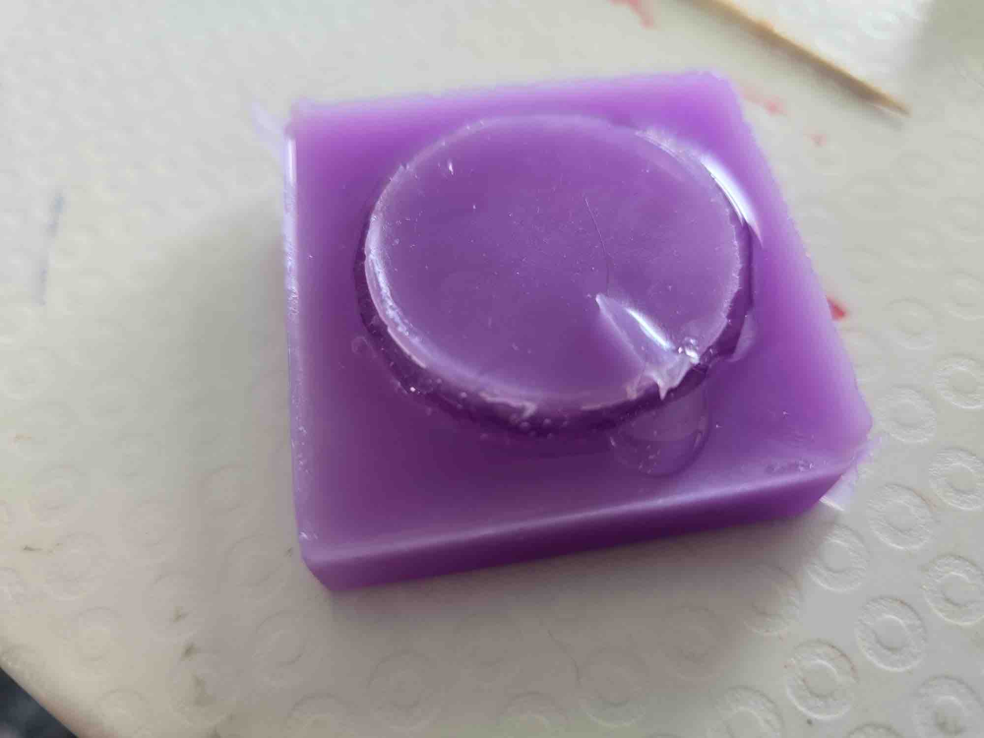
04 | Before closing the mould, I added more resin (kept liquid this time), then placed the second half of the mould on top and pressed it down so the resin would rise around the sides. Side effect of the earlier silicone leak: the negative mould came out shorter than designed, so the second half didn't seat as planned. I then left the closed mould under the UV lamp for 1 hour to fully cure.
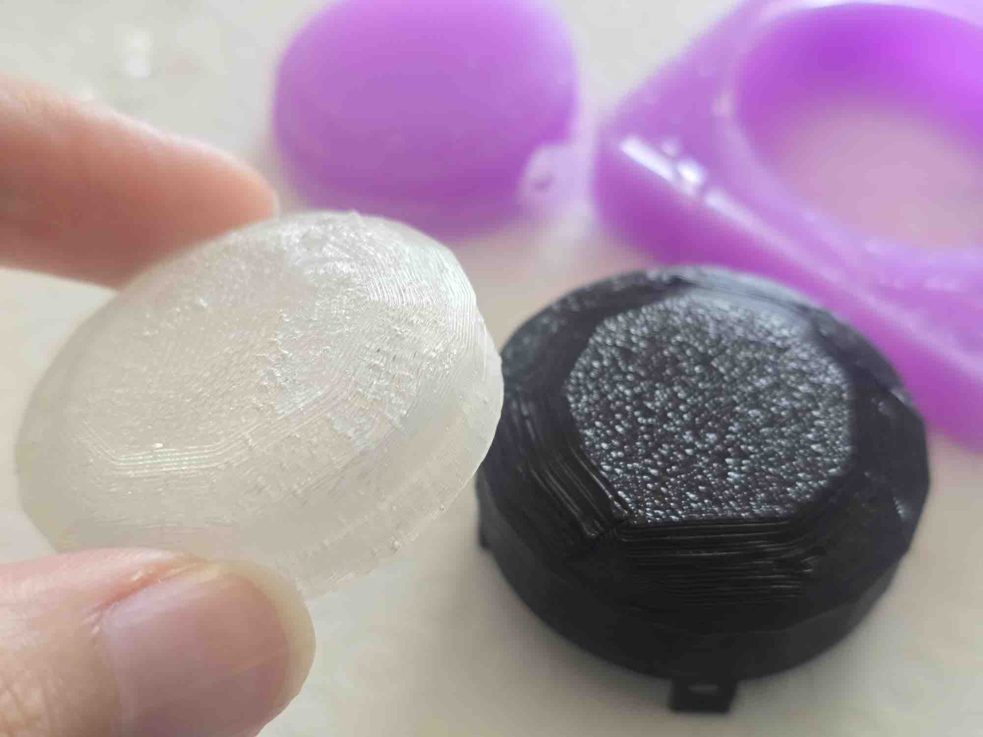
05 | After getting the case out, I left it under the UV light for 15 minutes to make sure it cured fully. This is how the final cast looks. The what suposed to be diamond-cut patterns from the mould have transferred onto the resin perfectly, the walls of the cast need to be thinker, the inside threads of the top case. The transperency is not as I imagines
- Feedback: I'm a real step closer to the cover I'd imagined at the start of the week. There's still a better workflow to discover for cleaner results — the leak-shortened mould, the residual bubbles, and the multi-layer pour technique are all things I'd refine in the next spiral.
- Challenge: Time, time, time — but I like that I've kept my mind clear and stayed focused on working to the schedule, not perfecting the task. That's the muscle I came to Fab Academy to build, and this week was one of its sharpest tests.