Assignment 4:- Embedded Programming
Learning Outcomes
This week, I learned about embedded systems and how microcontrollers work as the brain of electronic devices. I wanted to understand how they process data, manage memory, and control input and output pins.
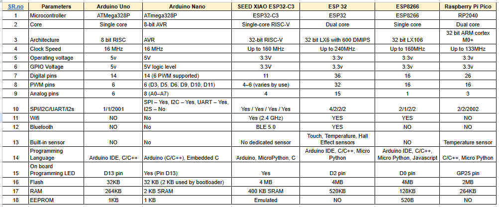
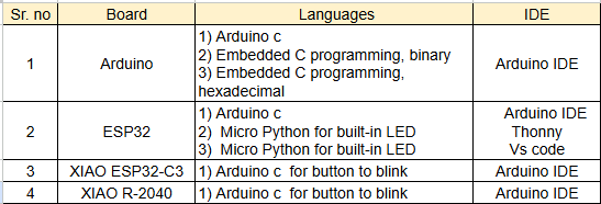
I worked with several development boards, including Arduino, Arduino nano, ESP32, Seed XIAO-espc3 and ESP-R2040.
I compared their architecture, clock speed, memory size, and communication features. This helped me see how to choose the right microcontroller for different applications.
I used different programming tools like Arduino IDE, Thonny for MicroPython, and VS Code. I discovered how compiled languages differ from interpreted ones. I learned how to compile code, upload it to the microcontroller, and run it without needing a computer.
During my experiments, I handled digital inputs and outputs, serial communication, and basic peripheral control. I also learned about communication protocols like UART. A key lesson was debugging.
I faced issues like port detection errors and upload failures, which showed me the importance of knowing boot modes and configuration settings. This experience deepened my understanding of the embedded programming process.
Group assignment:
Click Here Group Assignment Embedded programming
Compare the tools and processes used for various embedded architectures.
Understand the data sheets of microcontrollers.
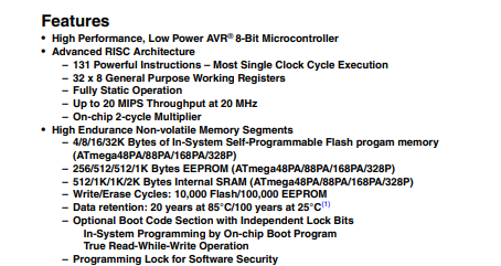
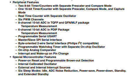
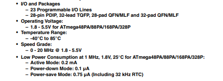
ATmega328P Datasheet
A datasheet is a complete technical document that provides detailed information about an electronic component. It explains how the device is designed, how it works, and how it should be used in a circuit.
The datasheet describes the internal structure, electrical characteristics, and operating conditions. It also gives a clear pin diagram and explains the function of each pin.
By reading the datasheet, we can understand how to properly connect and use the component in our project.
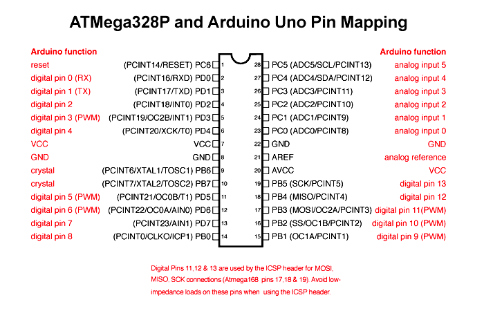
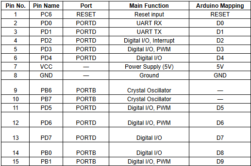
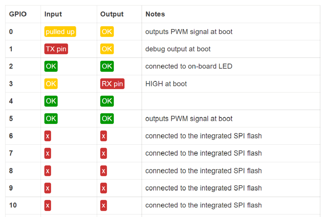
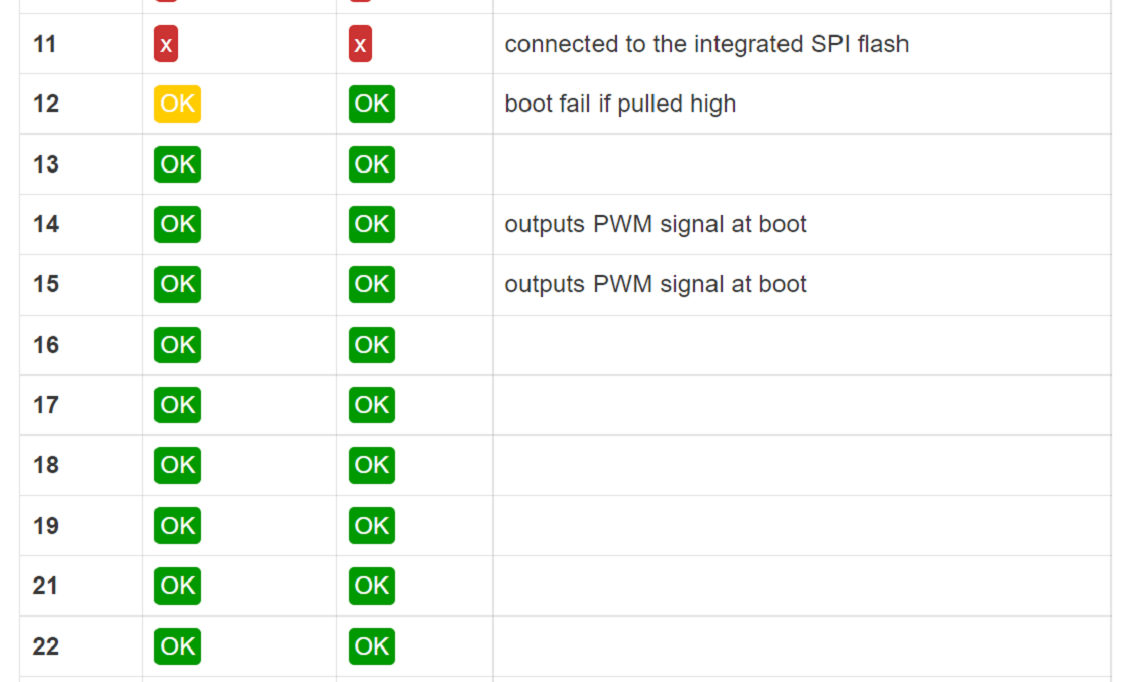
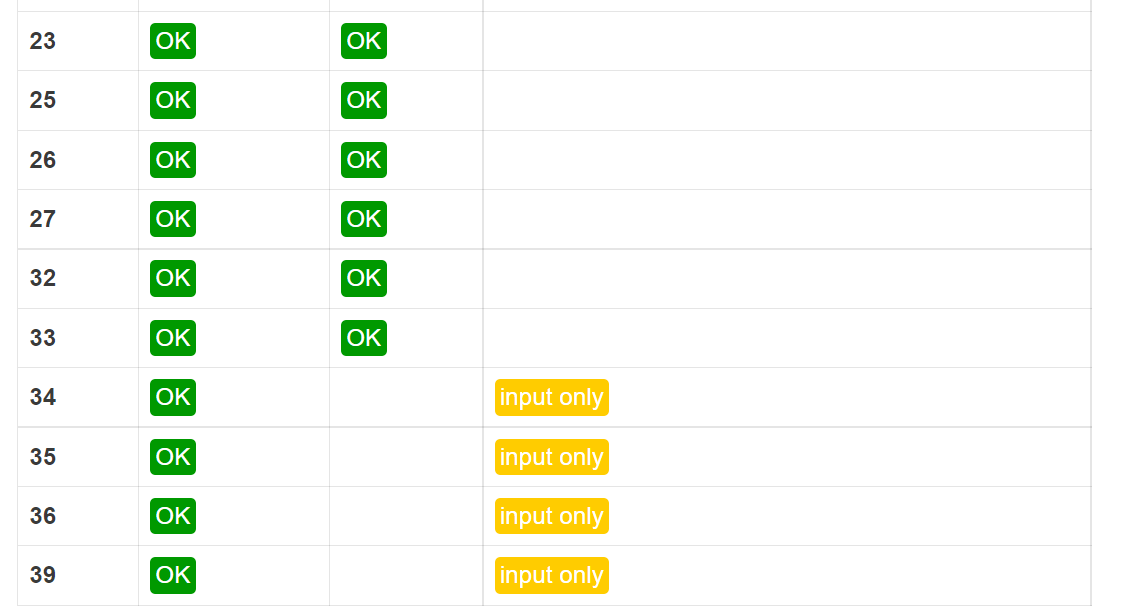
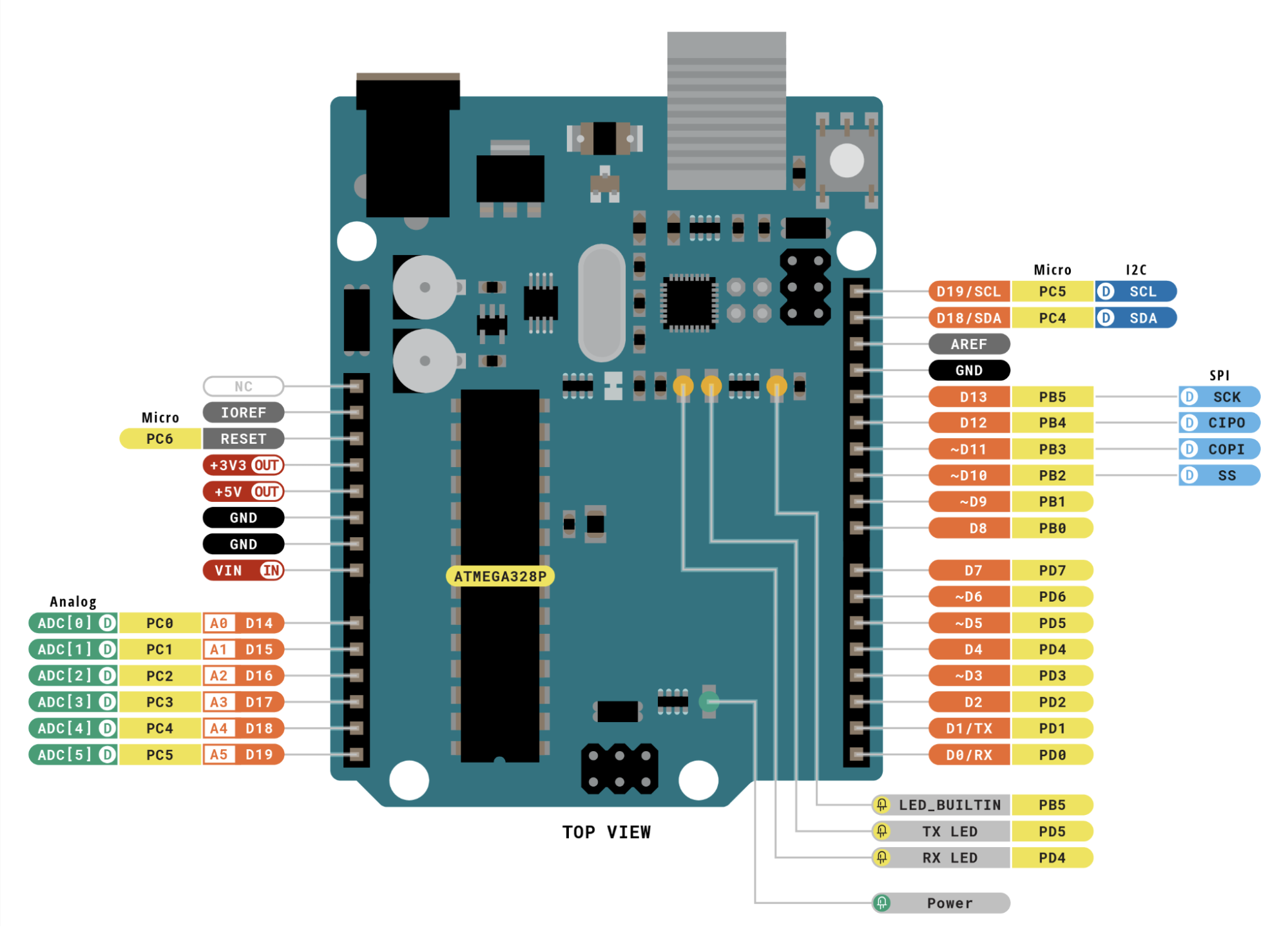
Pin Configuration :
In a microcontroller, there are many pins and each pin has a special function. Some pins are used as digital input and output,
while some are used for analog input to read sensor values. Certain pins support PWM to control things like LED brightness or motor speed.
Other pins are used for communication protocols such as SPI, I2C, or UART to connect with external devices.
Each pin has a specific role, which helps the microcontroller perform different tasks efficiently.
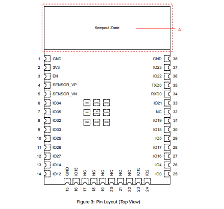
ESP32 Datasheet
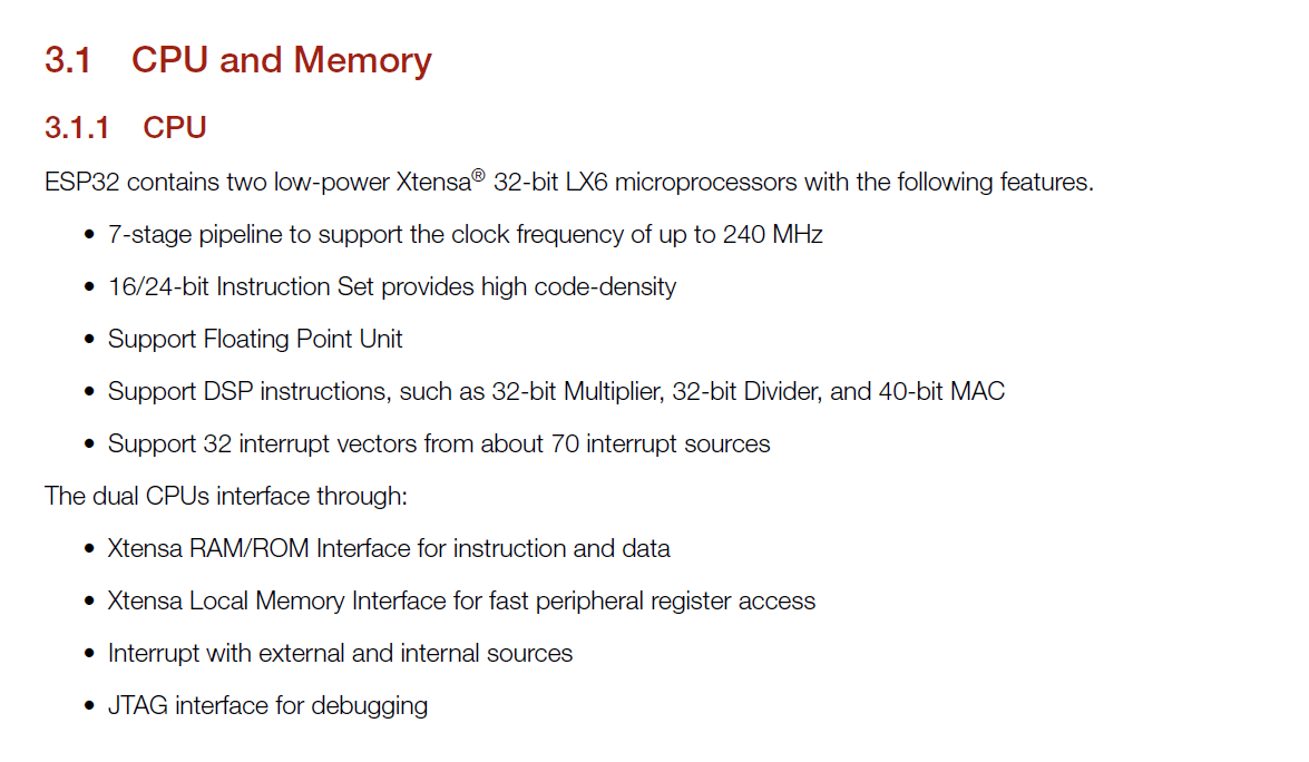
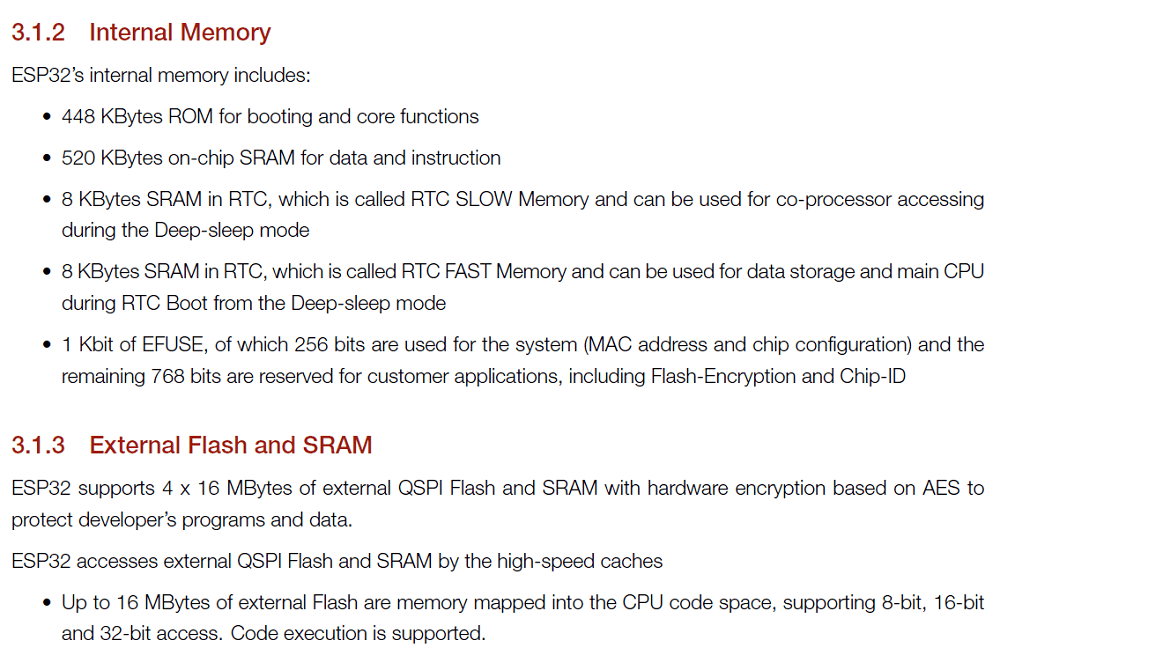
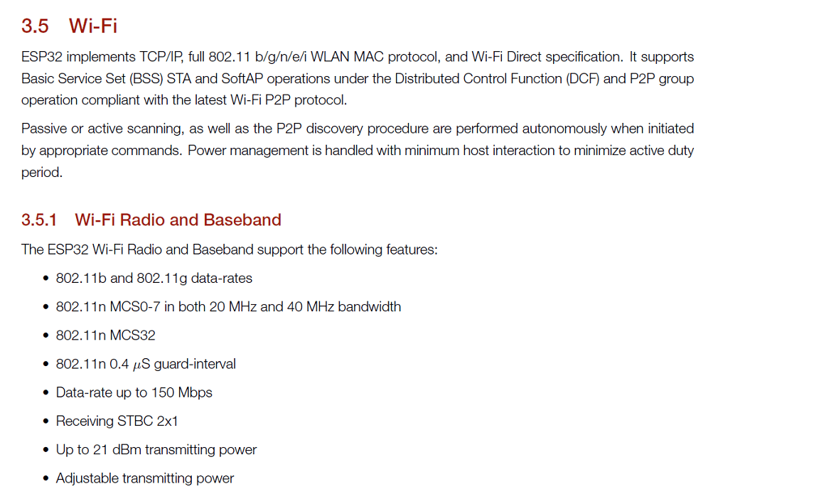
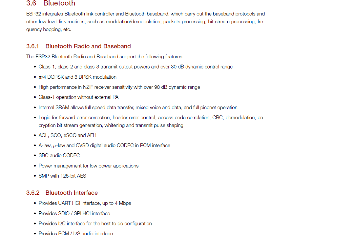
ESP32 is a more advanced microcontroller board compared to Arduino Uno. It has built-in WiFi and Bluetooth,
so we can connect it directly to the internet or other wireless devices without using extra modules. It also has more processing speed, more memory, and more GPIO pins.
ESP32 supports advanced features like dual-core processing and multiple communication options. Because of these extra features, it is very useful for IoT and smart projects.
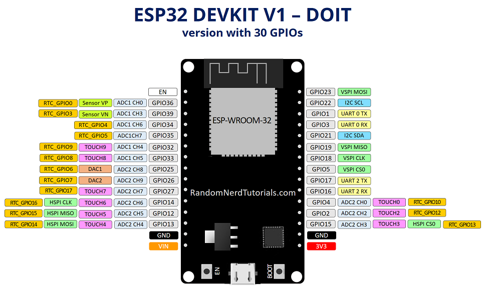
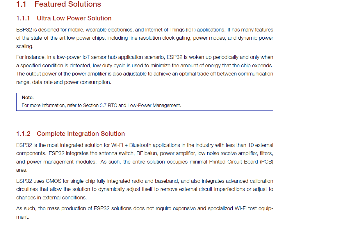
ESP32 Features
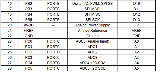
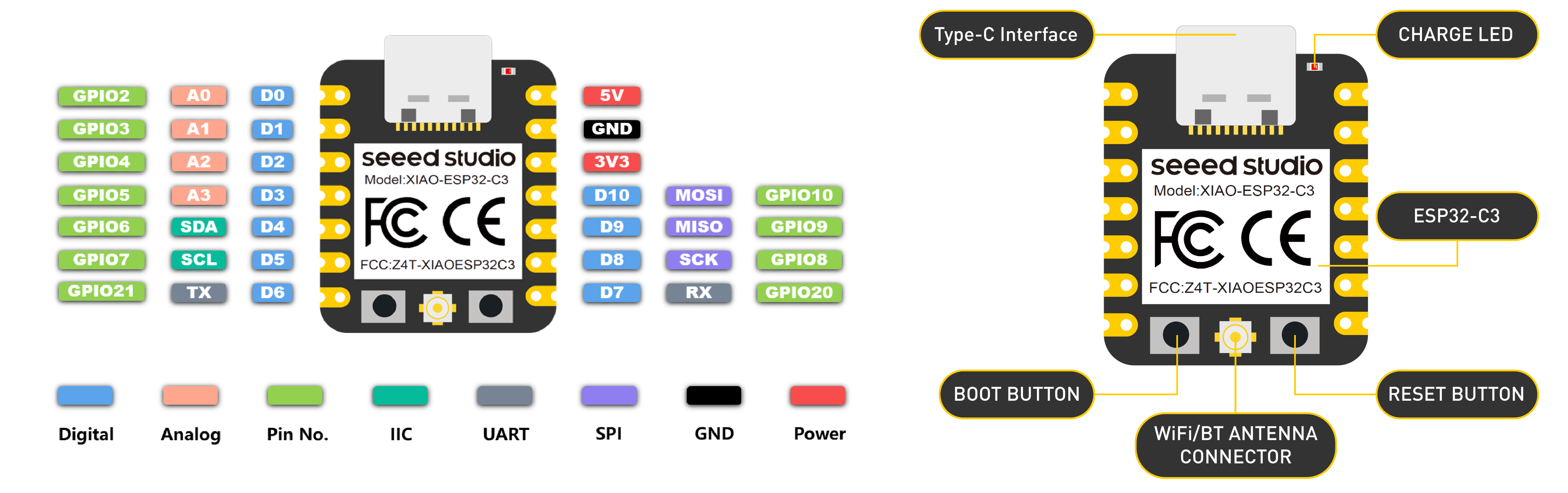
Pin Configuration :
Comparison of Microcontrollers
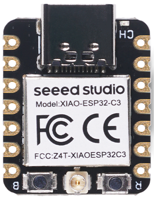
PCB for the XIAO ESP32-C3 :
this assignment, we worked as a group and designed a custom PCB for the XIAO ESP32-C3 module because it does not have an onboard LED.
To test and practice programming easily, we decided to add an external LED on our own board. We fabricated the PCB using the etching process.
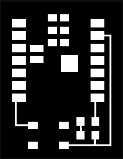
Step 1: In this week’s video lecture, Nils Gershenfeld explained different types of microcontroller boards and described their features and architecture.
During the lecture, he also showed PCB traces and how microcontroller boards are designed internally. From the lecture, we understood the PCB trace layout of the XIAO ESP32-C3 module. This helped us learn how to design and plan our own custom PCB board.
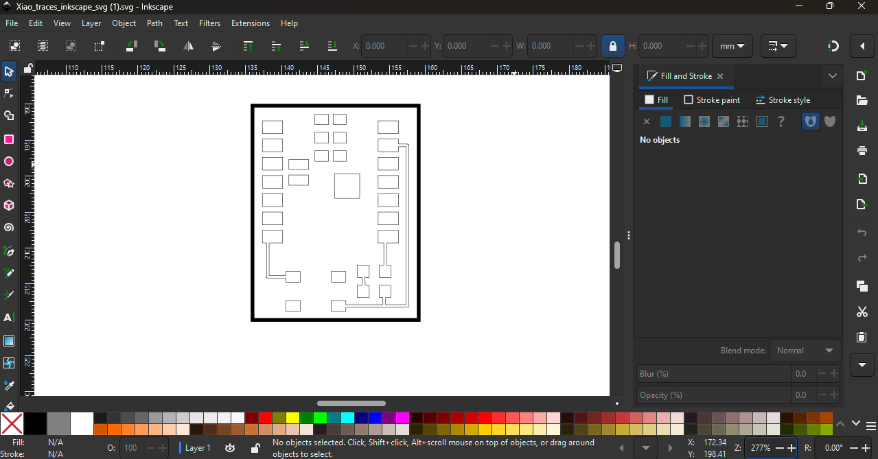
Step 2: Our plan was to use the laser machine during this process. So first, we converted the PCB trace image into vector format using Inkscape software.
Converting the image into vector format helped us prepare the design properly for laser cutting.
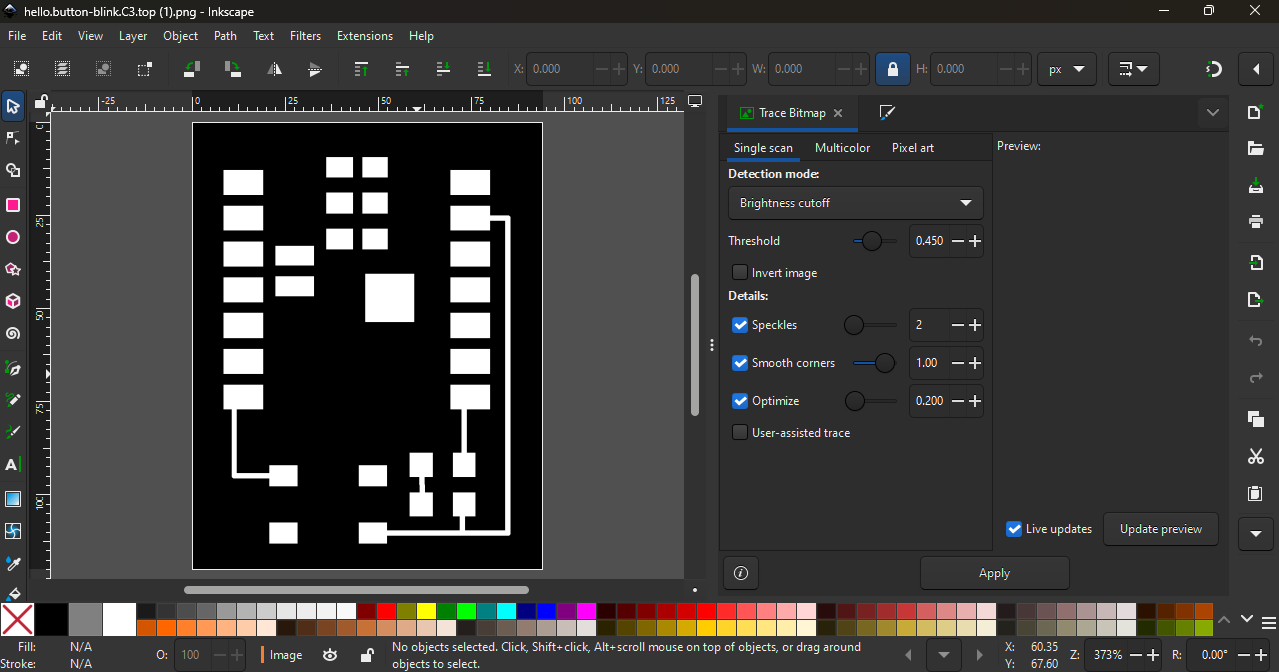
This step was important to make sure the traces were clean and accurate before moving to the next fabrication process.
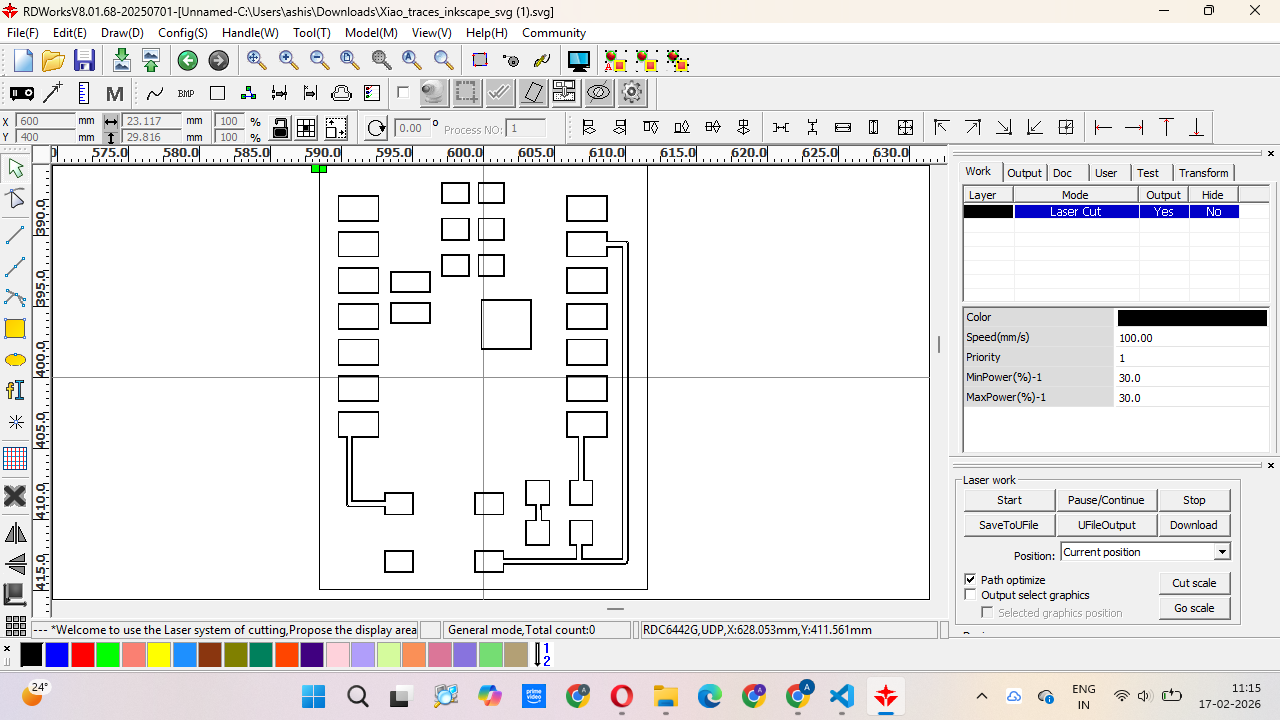
Step 3: After preparing the vector file, we imported it into RDWorks software and converted the design into a machine path for the laser cutter.
However, we were using an 80W CO₂ laser machine, which cannot directly engrave or cut metal surfaces. Since our PCB base was a copper plate, the laser could not engrave it directly.
So we tried different masking materials like paper tape, electrical tape, and vinyl paper to see which one would work properly for the process.
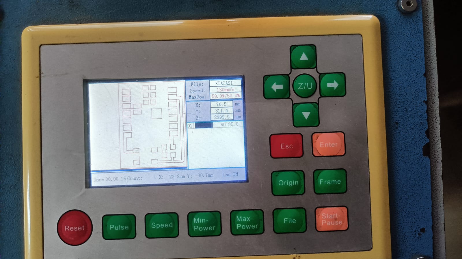
We tested the laser cutting process multiple times on different materials. We tried paper tape, electrical tape, and vinyl paper to check which material gave the best result.
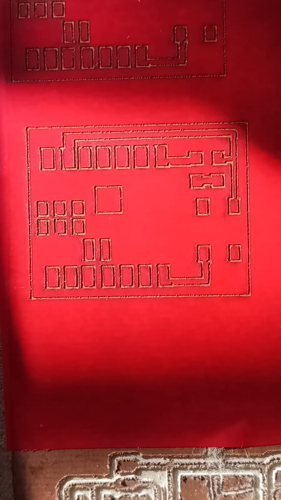
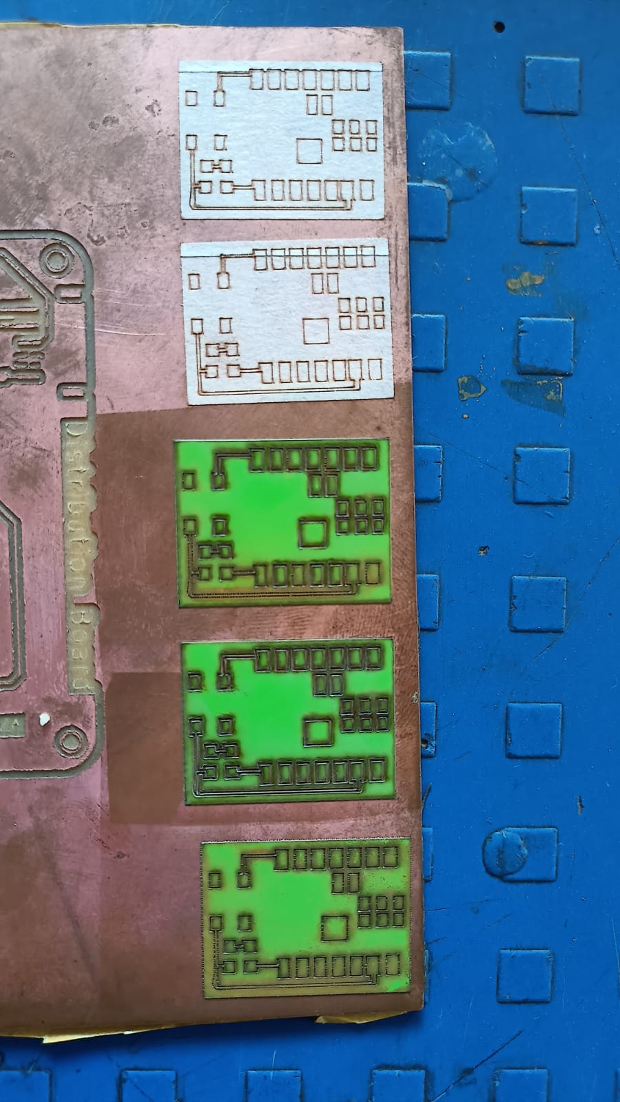
After testing different materials, we selected the best material for the cutting process.
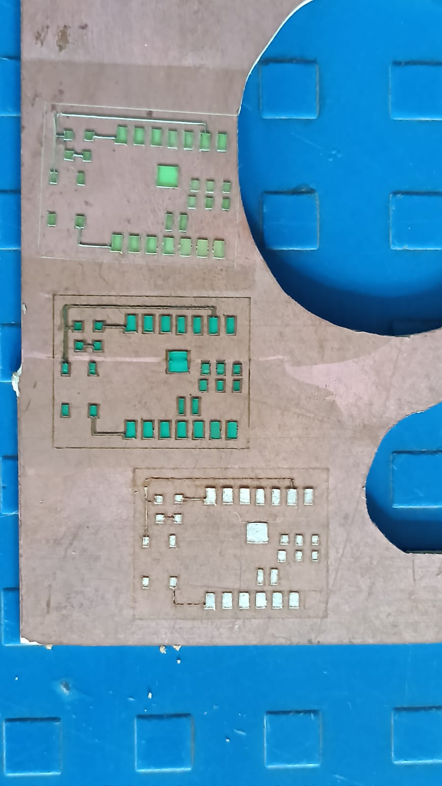
During this step, we made a small mistake — we forgot to invert (mirror) the PCB image before sending it to the laser machine.
Because of this, the first cut was incorrect. We understood the mistake, corrected the design by inverting the image, and then repeated the cutting process to get the final correct output.
During PCB cutting using the grinder cutting machine, the cutting blade was too close to the PCB traces. This caused slight damage to the copper cladding at the corners and edges of the board.
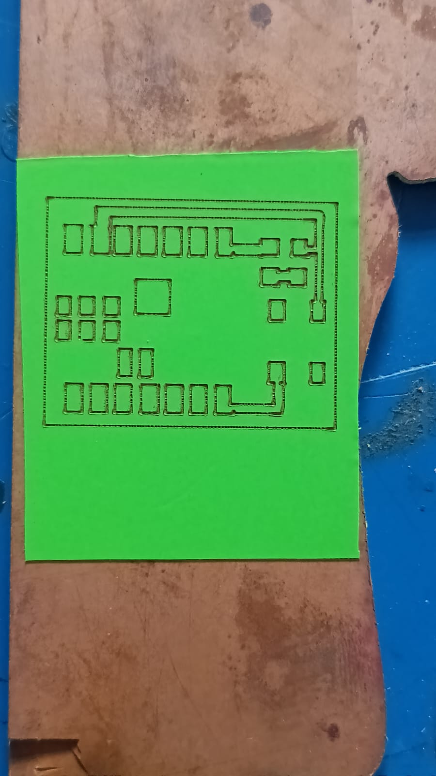
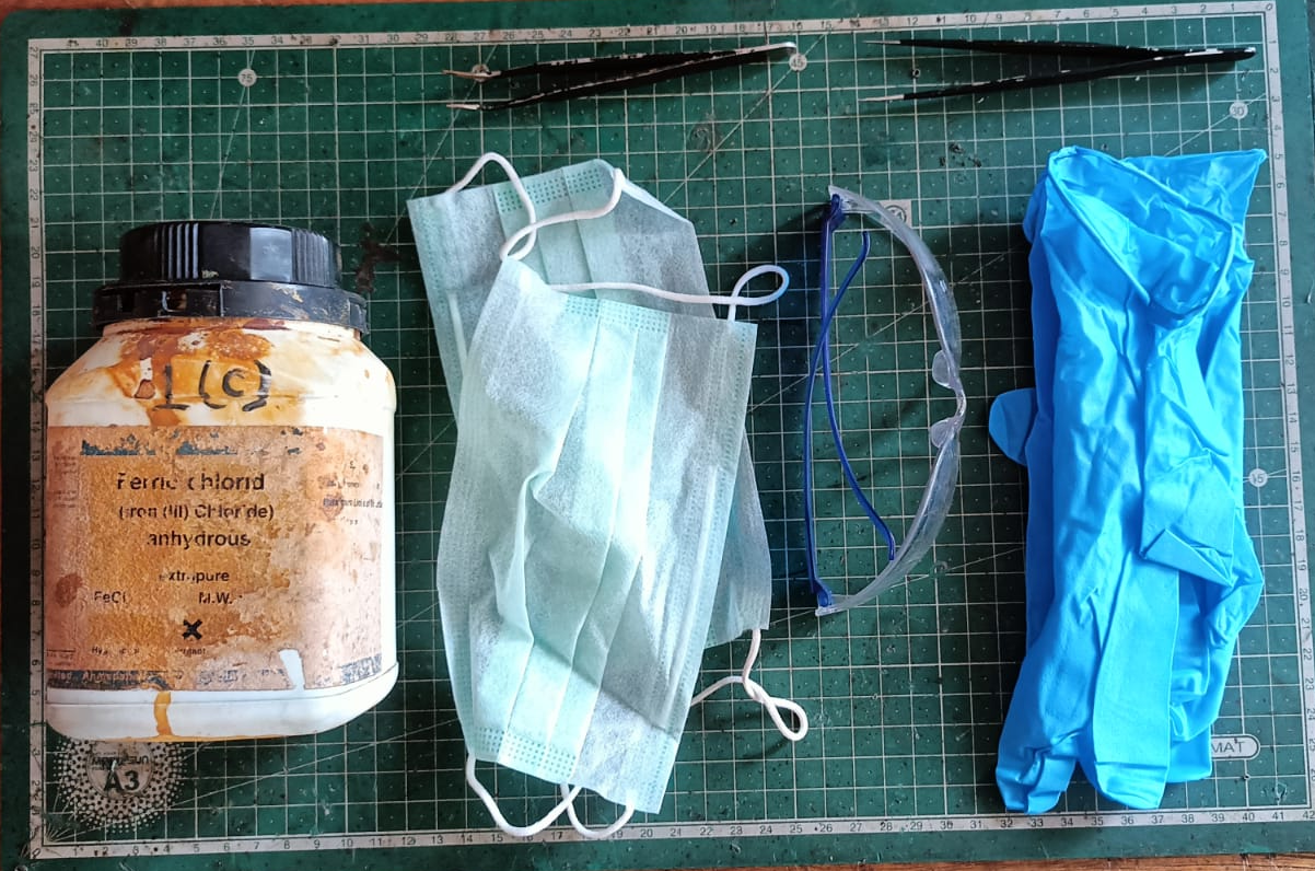
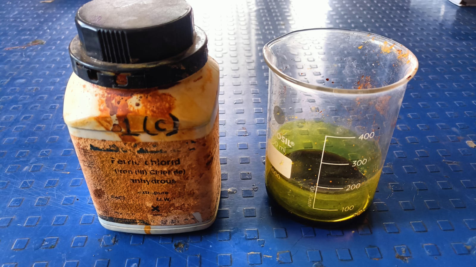
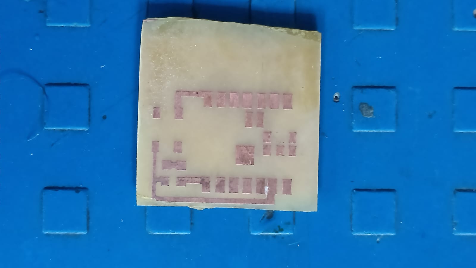
The next step was the chemical etching process. For this step, we followed proper safety precautions because chemicals were involved. We used ferric chloride solution mixed with distilled water to remove the unwanted copper from the board.
We also used the required tools like gloves, a container, and safety glasses during the process.
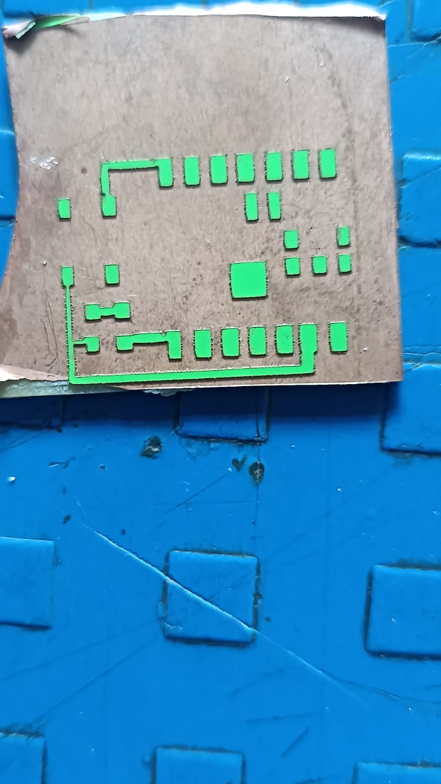
After immersing the board in the etching solution, we observed the chwmical rection as the unwanted copper was removed, leaving behind the desired PCB traces.
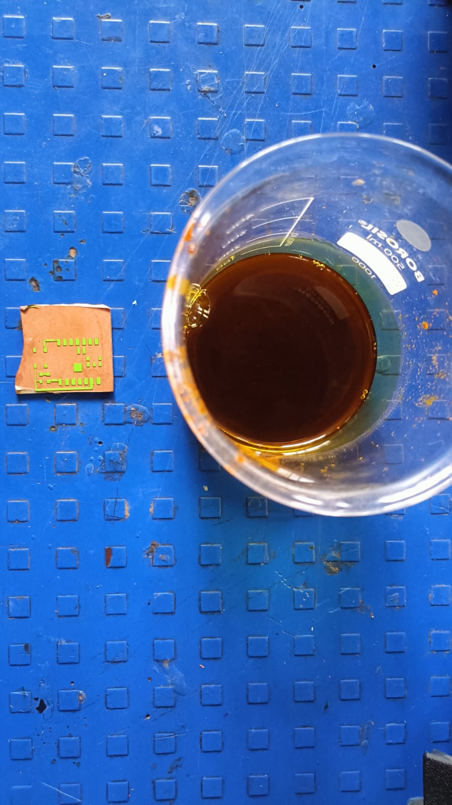
We monitored the process closely to ensure the traces were clear and well-defined before taking the board out of the solution.
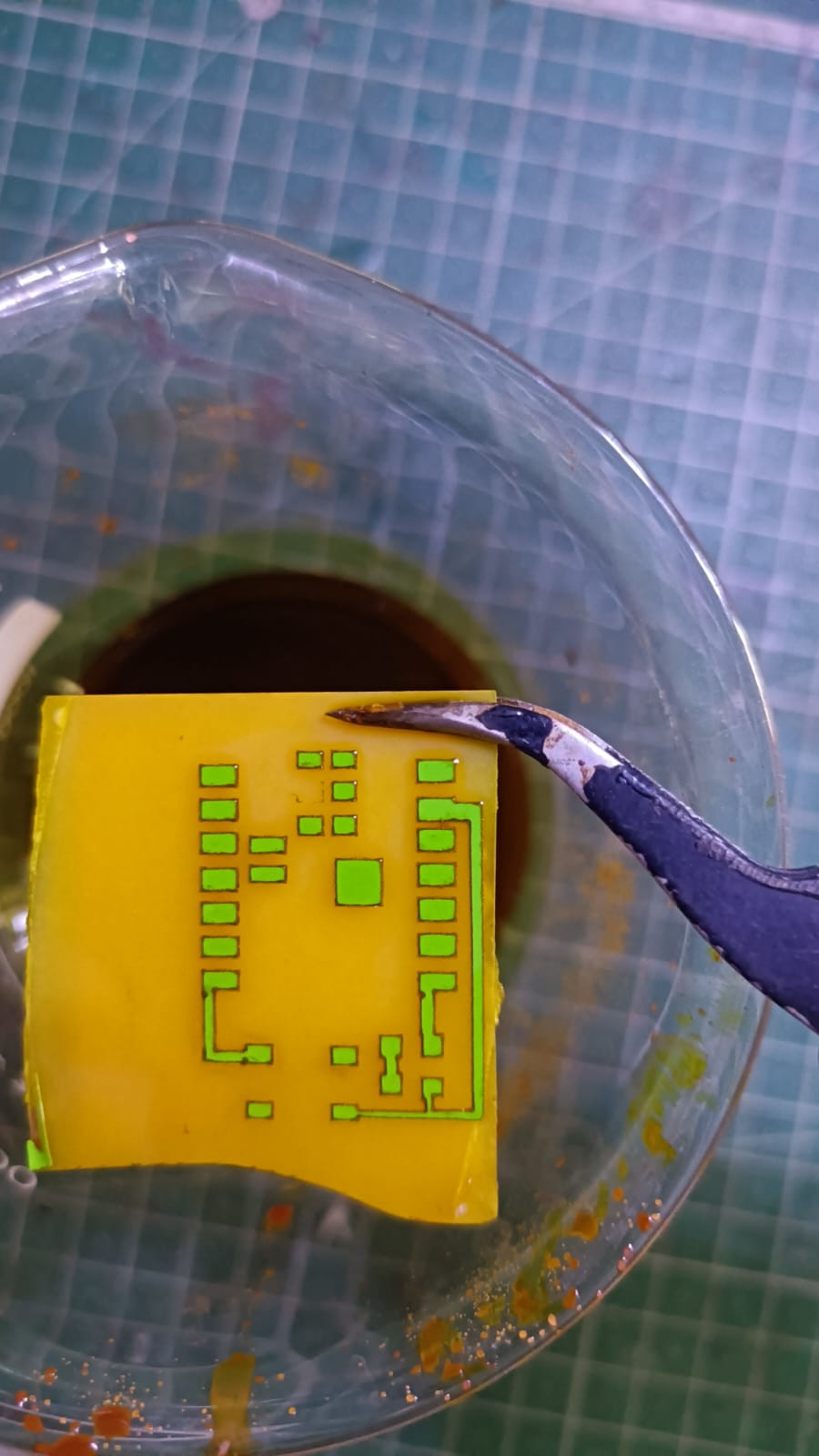
This step helped us achieve the final PCB traces on the copper plate.
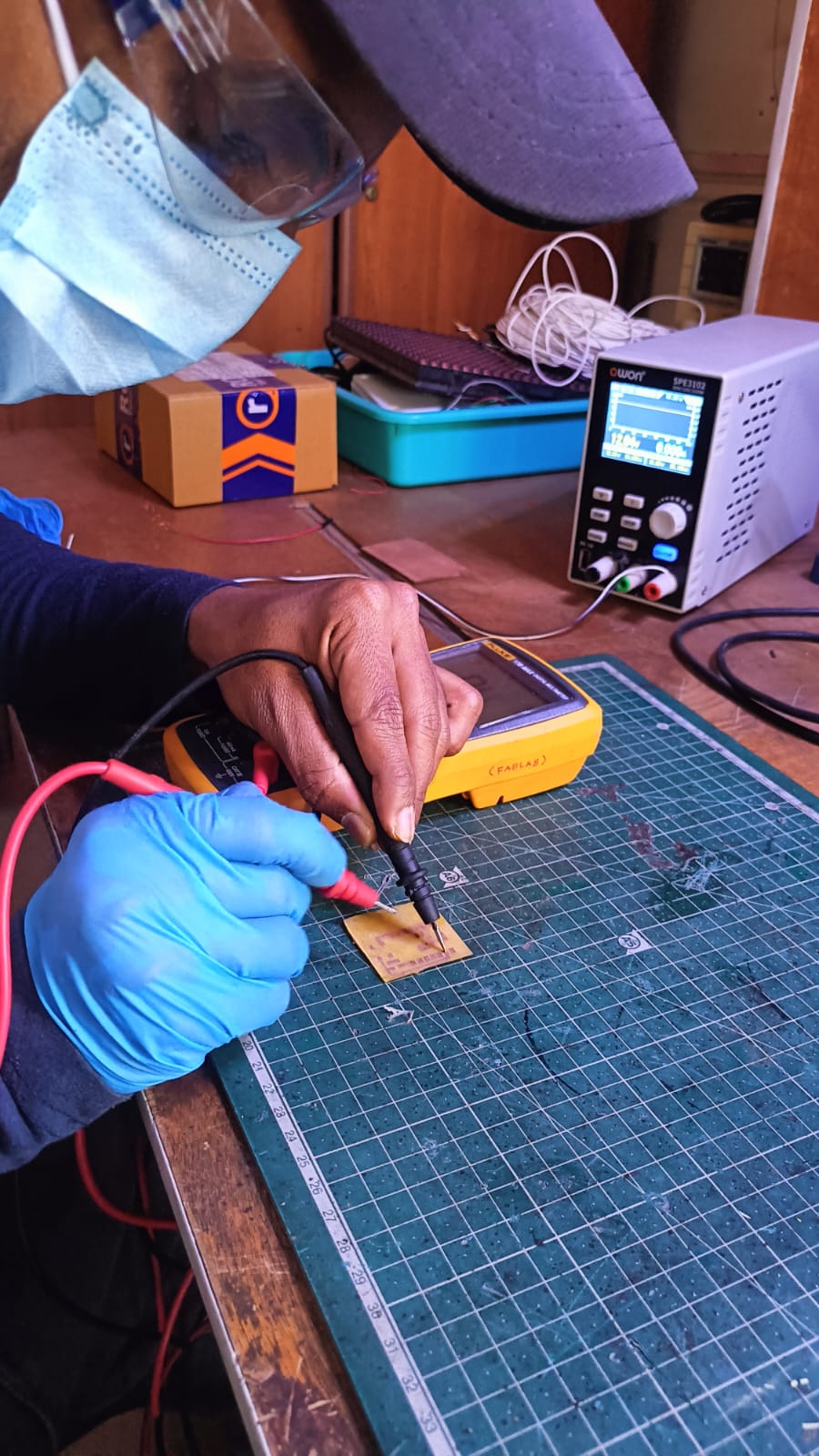
Before soldering, I checked all the PCB traces using a multimeter to ensure there were no short circuits or broken connections.
After confirming everything was correct, I soldered one push button, a 1k resistor, and a red LED according to the circuit design. Once soldering was completed, the board was tested and worked successfully.
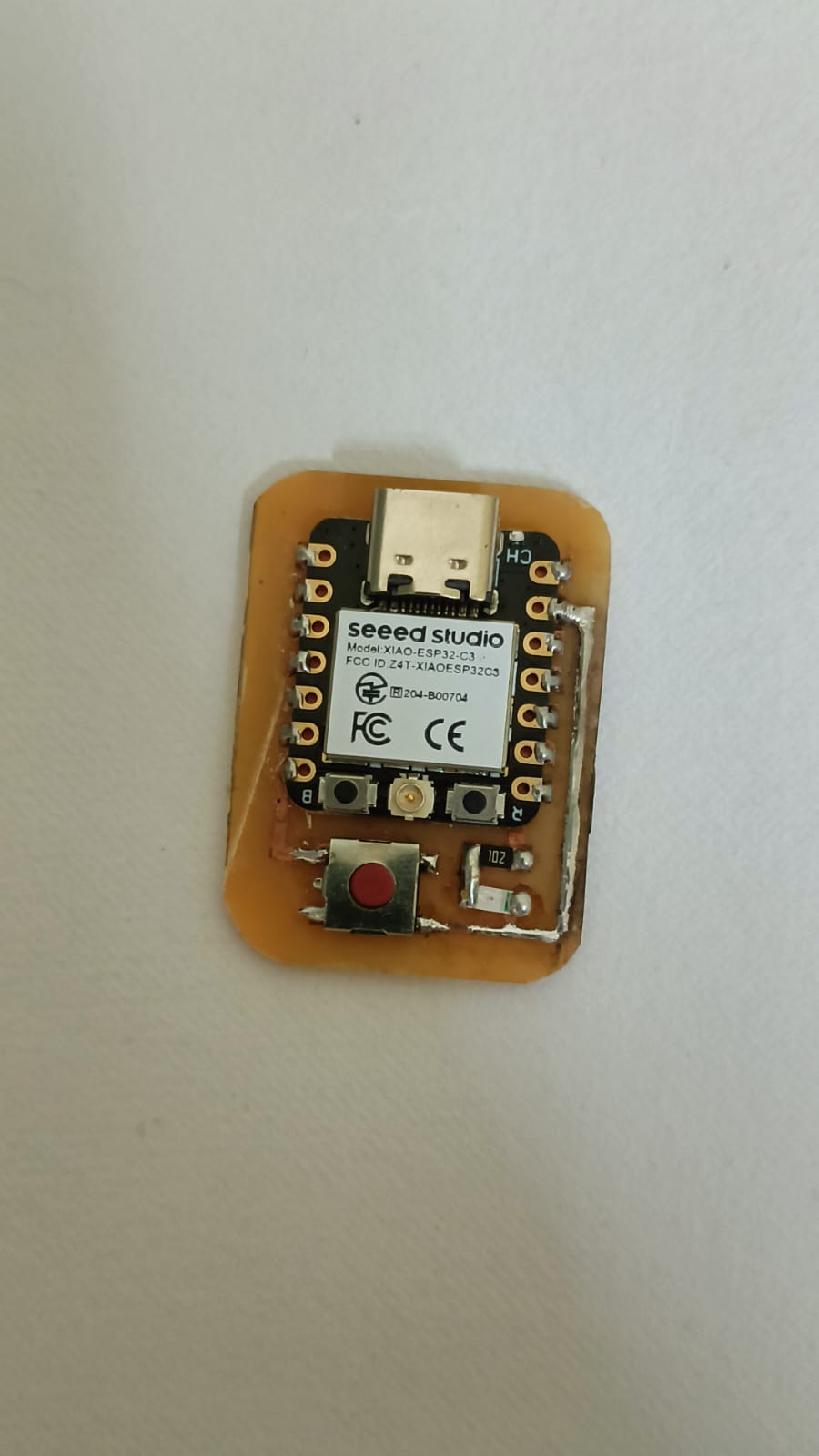
In the next step, I tested the LED using Arduino IDE. I wrote and uploaded a program to control the LED with the push button.
After connecting the board properly, I checked whether the LED turned ON and OFF when the button was pressed. The test was successful, and the circuit worked as expected.
Individual Assignment:
Embedded Systems
Embedded programming is about writing tiny programs for small computers called microcontrollers.
These programs help boards like Arduino and ESP32 control things like turning lights on and off,
reading sensors, and moving motors. The program is stored in the chip and runs all the time to do its job.
Unlike regular computer programs, embedded programs only do one thing and usually work with less memory and speed.
To understand these systems, you need to learn how the parts connect and how they send and receive signals. In simple words,
embedded programming helps make electronic devices smart by using code.
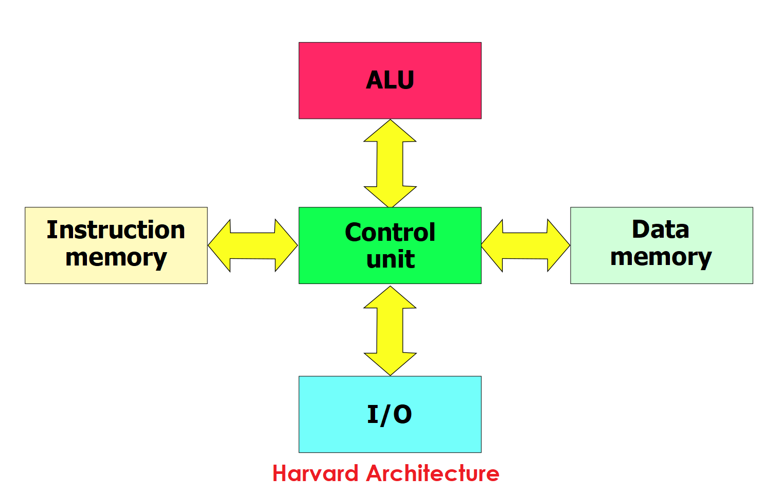
Architecture
In Harvard architecture, the microcontroller has two different memory paths — one for instructions (code) and one for data. So it can read both at the same time, making it faster.
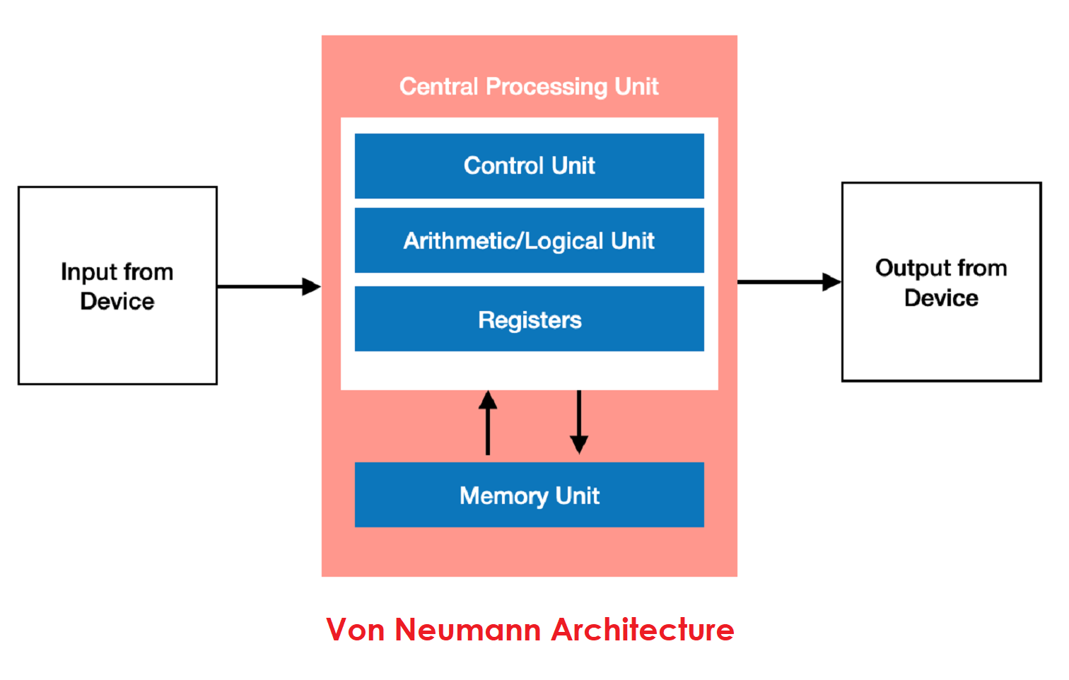
In Von Neumann architecture, there is only one memory and one path. So it must handle code and data one after another, which can reduce speed.
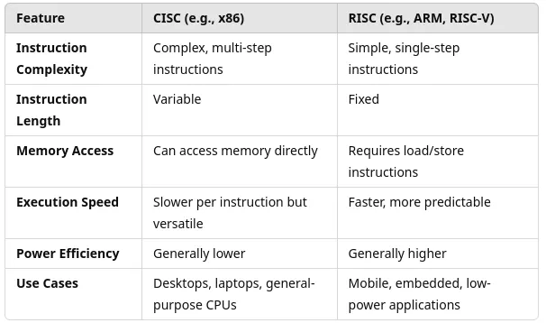
CISC vs RISC Architecture
RISC:-RISC (Reduced Instruction Set Computer):RISC has a small number of simple instructions that run very quickly, usually in one clock cycle. Because of this, it is commonly used in microcontrollers and embedded systems.
CISC:- CISC (Complex Instruction Set Computer) : CISC has many complex instructions that can perform multiple tasks in one command. This helps reduce the amount of code, but it makes the processor design more complicated.
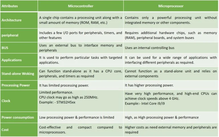
Microprocessor vs Microcontroller
Microprocessor:- microprocessor is the main processing unit (CPU) of a computer. It can perform calculations and process data, but it needs external components like RAM, ROM, input/output ports, and other hardware to work properly.
Microprocessors are usually used in computers and laptops where high processing power is required.
Microcontroller:-A microcontroller is a small computer on a single chip. It has a CPU, memory (RAM and ROM), and input/output pins built inside the same chip.
Microcontrollers are mainly used in embedded systems like Arduino boards, washing machines, remote controls, and other smart devices where a specific task needs to be performed.
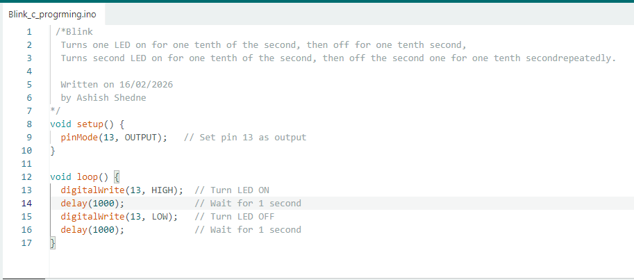
1:- Arduino programming with Embedded C
Write the code in Embedded C for the Arduino onboard LED using the Arduino IDE.
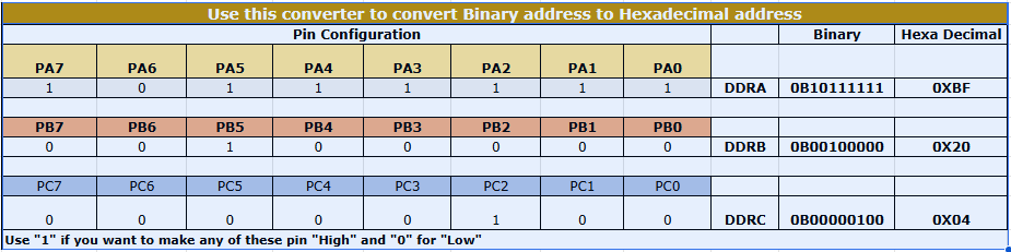
This chart was made by Kiran Sir during Fab Academy 2022. It helps us understand how binary and hexadecimal values are used for microcontroller port pins.
My instructor, Kisor Sir, explained to me how this chart works and how to use it in coding. Because of his guidance, I understood how to calculate bit values and use them in Embedded C programming.
2 Arduino blink program using hexadecimal values to control the onboard LED.
avr/io.h is used to access microcontroller registers like DDRB and PORTB, and
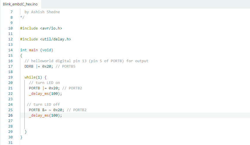
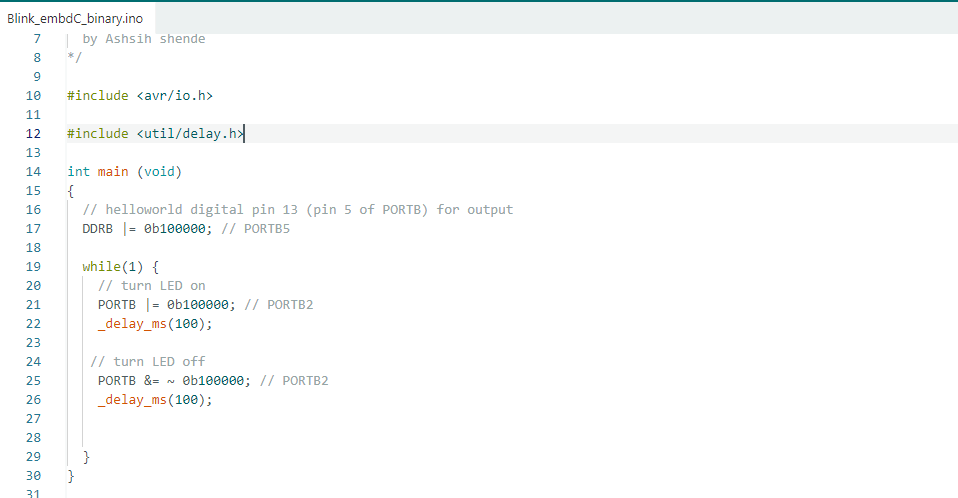
3:- Arduino blink program using binary values to control the onboard LED.
LED (Pin 13 / PB5) of the Arduino. The
Thonny IDE
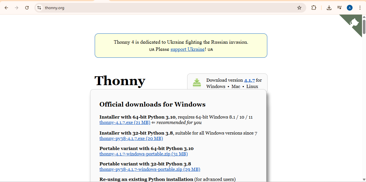
4:- used the ESP32 board to blink an LED using Thonny and MicroPython. To install Thonny on a Windows PC, we first went to the official Thonny website.
Click here to go to the Thonny website
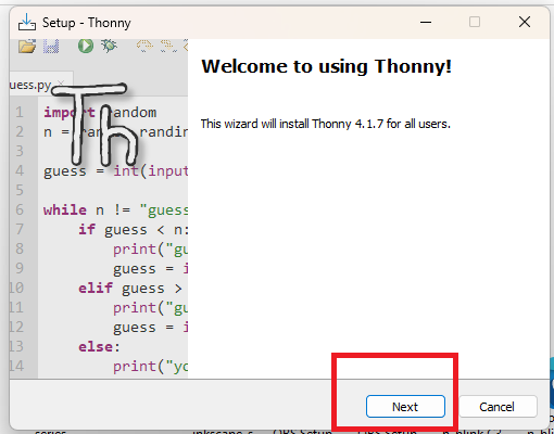
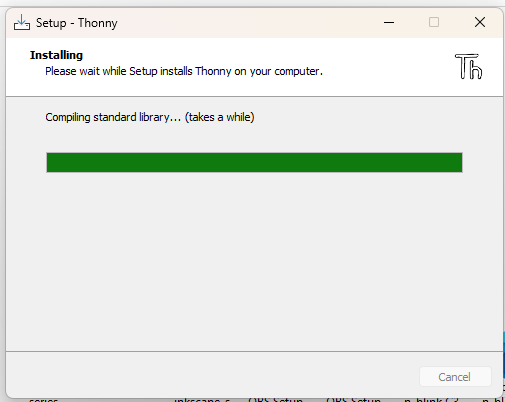
After downloading the file, just click on the setup file and install it on my system.
After installing, open the software and configure the required settings. Make sure your board is connected to your system before changing the settings.
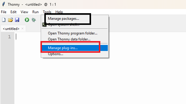
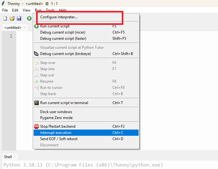
Next, go to Tools → Options → Interpreter to configure the interpreter settings.
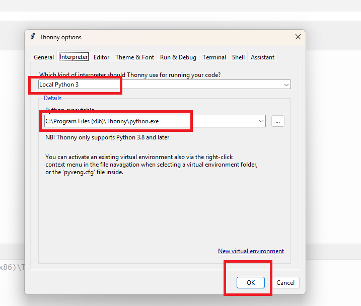
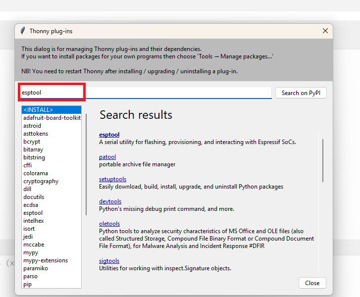
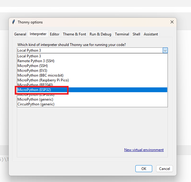
In the next step, select MicroPython (ESP32) in the interpreter options. Then check and choose the correct COM port where your device is connected.
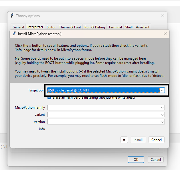
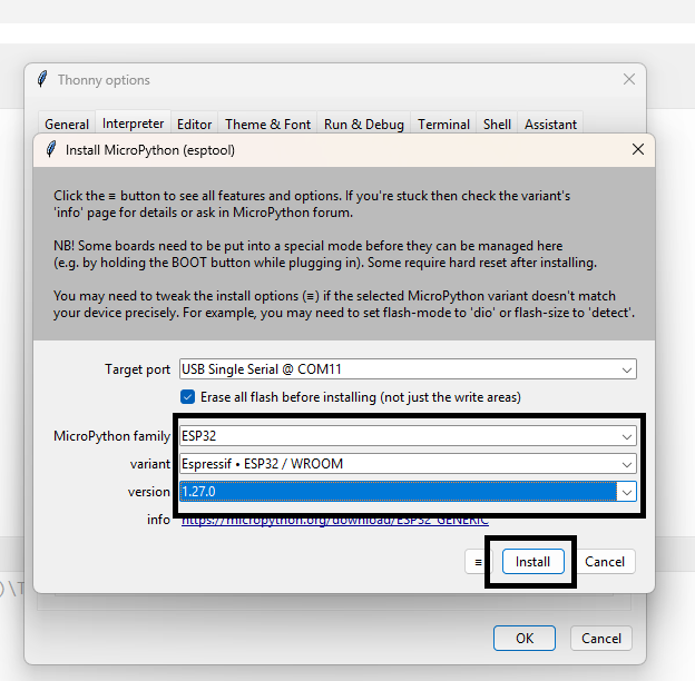
Check your ESP32 module type, select the correct device in Thonny, and then install the MicroPython firmware if required.
If the firmware is not detected or installed properly, press the reset button on the ESP32 board while connecting or installing the firmware.
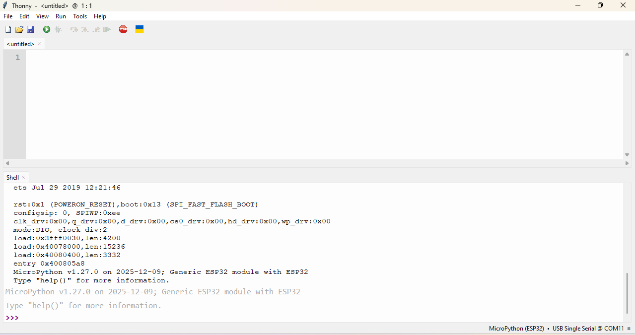
After finishing all the setup, Write a simple program for the ESP32 using MicroPython in Thonny to test the board.
in this program code, will blink the onboard LED of the ESP32 this code gets from the ChatGPT.
VS code
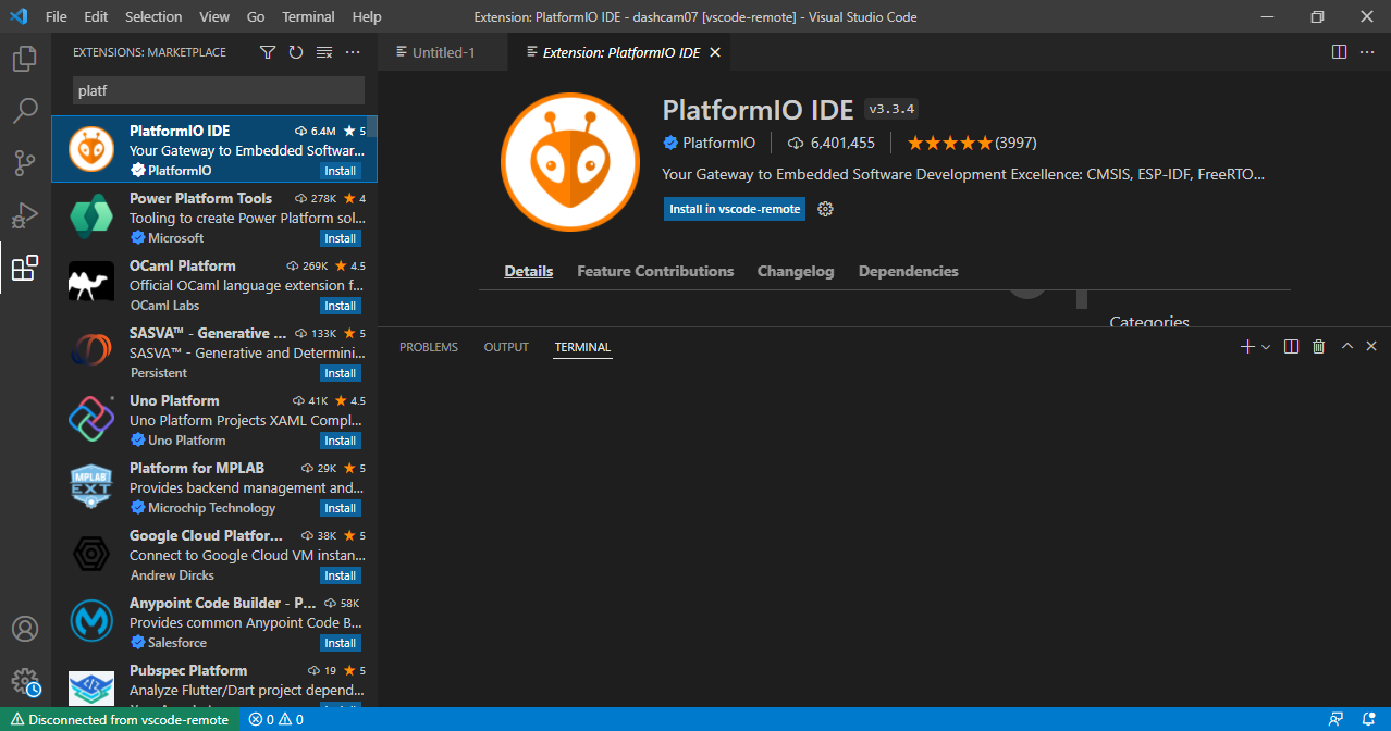
5:- I also used VS Code to program my ESP32 module and blink the LED.
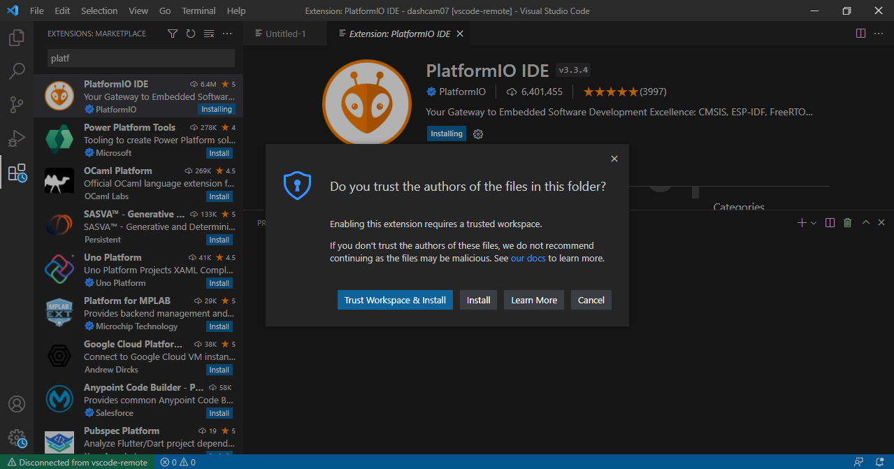
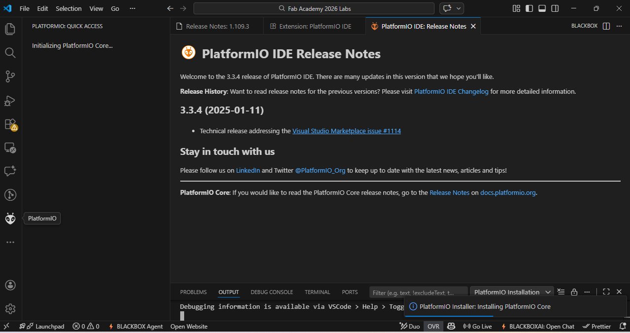
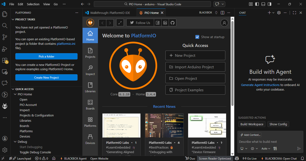
Before starting programming, we need to set up some things in VS Code. In the first step, we install the PlatformIO extension to support ESP32 development.
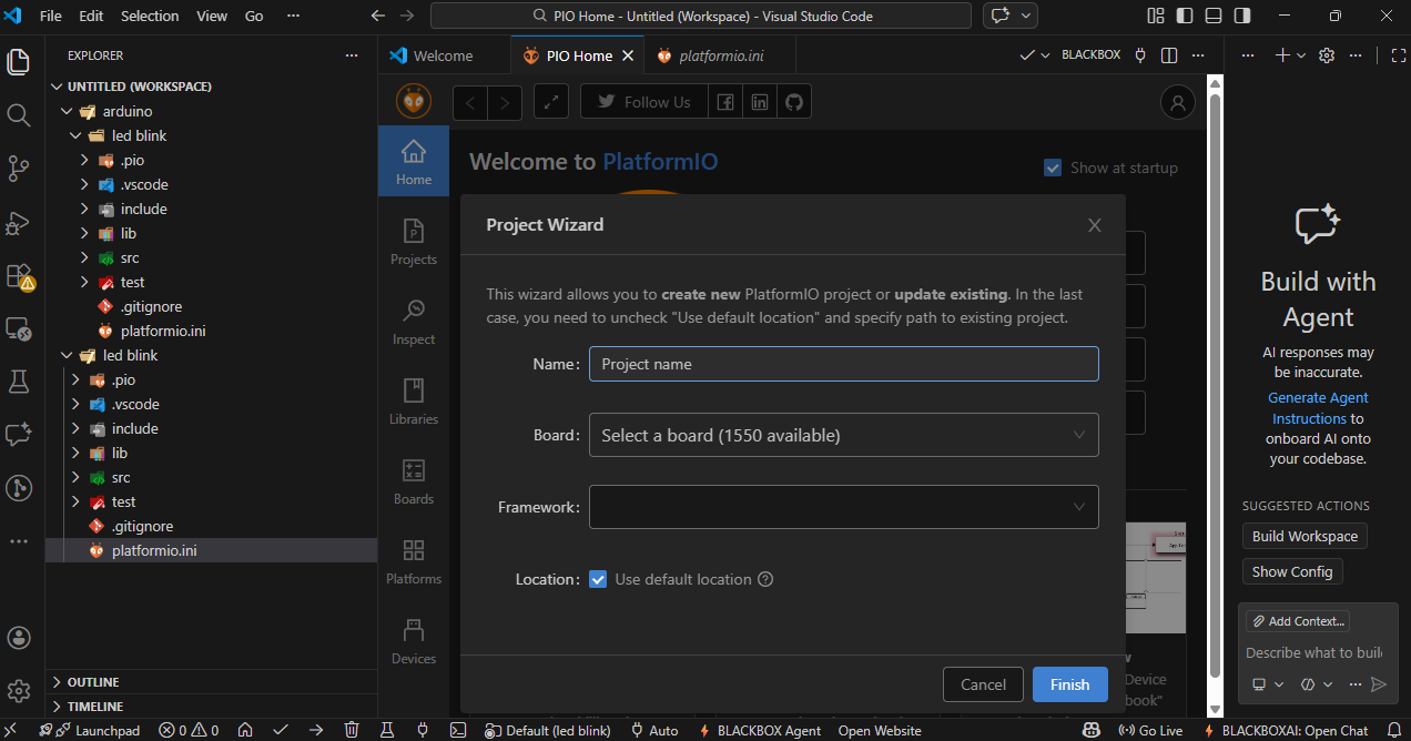
After installing, click on the PlatformIO icon, then create a new project and give your project a name.
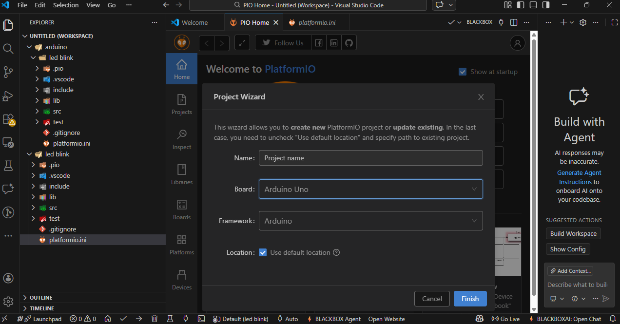
In the next step, select your board type and choose the appropriate framework (such as Arduino). click on Finish to create the project.
After completing all the setup, open the main.cpp file from the left side panel and write or edit your main code there.
Once your code is finished, you will see small icons at the bottom. The ✓ (check mark) icon is used to verify or compile the code, and the → (arrow) icon is used to upload the code to the ESP32 board.
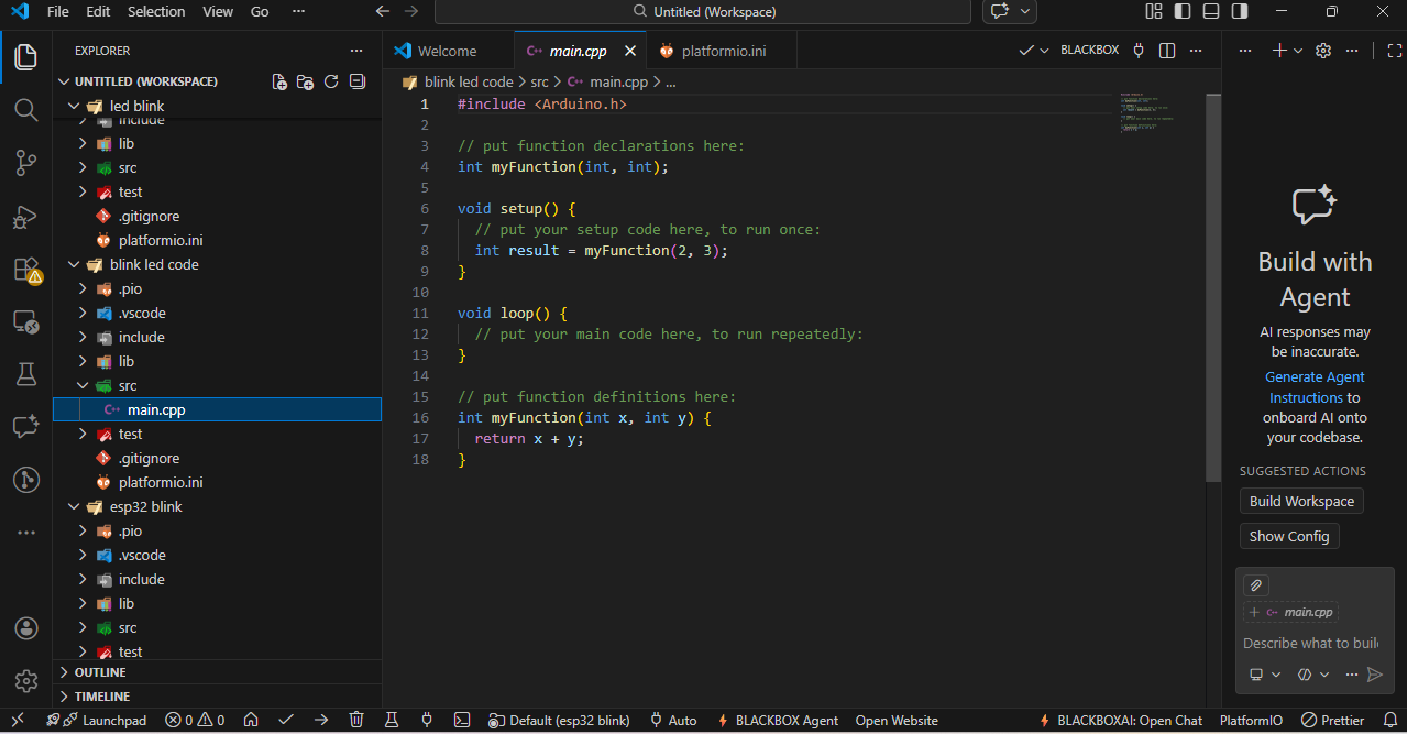
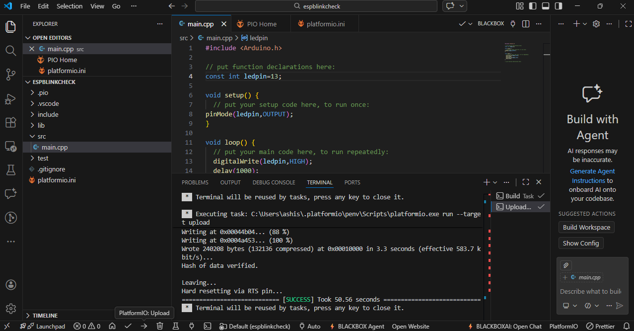
I wrote a basic program to blink the onboard LED of the ESP32.
RP2040
6:-I used the RP2040 LED blink code written in Arduino C programming language that was provided in our Fab Academy class. I uploaded the same code to my RP2040 board. After uploading, I opened the Serial Monitor and entered a number as input. Based on the number I entered, the LED started blinking.
Download all the code here
Facing problems
1) During the process of programming and testing, I faced some issues. One of the main problems was that my computer was not detecting the COM port when I connected the ESP32 board. This issue was frustrating because it prevented me from uploading the code to the board. After some troubleshooting, I found out that the problem was related to the USB cable I was using.
2) Another issue I faced was during the PCB fabrication process. When I was trying to etch the PCB, I accidentally left it in the etching solution for too long, which caused some of the traces to become too thin and weak. This made it difficult to solder components onto the board, and I had to redo the PCB fabrication process to get a better result.
3) I also had some trouble with the Thonny IDE when trying to install the MicroPython firmware on the ESP32. The installation process was not straightforward, and I had to try multiple times to get it right. I had to reset the board several times and check the COM port settings to successfully install the firmware.
4) Additionally, I faced some challenges with the VS Code setup for ESP32 programming. The PlatformIO extension had some compatibility issues with my system, which caused errors during the project creation and code upload process. I had to update my VS Code and PlatformIO extension multiple times to resolve these issues and get everything working smoothly.
References