Assignment 16 :- Wildcard Week
Learning outcomes
In this week’s task, I designed and produced something using a digital process, including computer-aided design and manufacturing, which was not covered in another assignment. I also documented all the requirements and included everything necessary to reproduce the project.
According to the task, I learned about a new machine and designed a table lamp. During this learning process, I also learned new software used for a plasma cutter.
- I learned how to use sheet metal module in solidworks
- I learned how to use FastCAM software to generate G-code for the plasma cutting machine.
- I learned how to operate the CNC plasma-cutting machine.
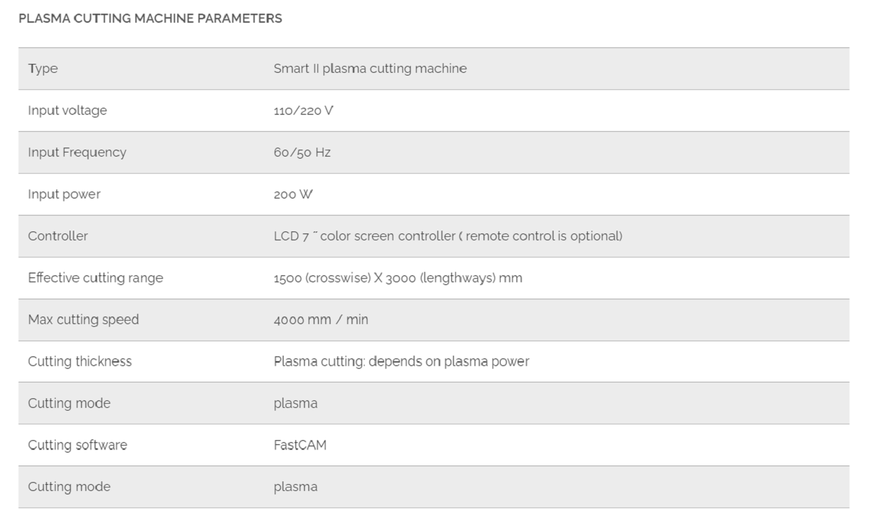
CNC plasma-cutting machine
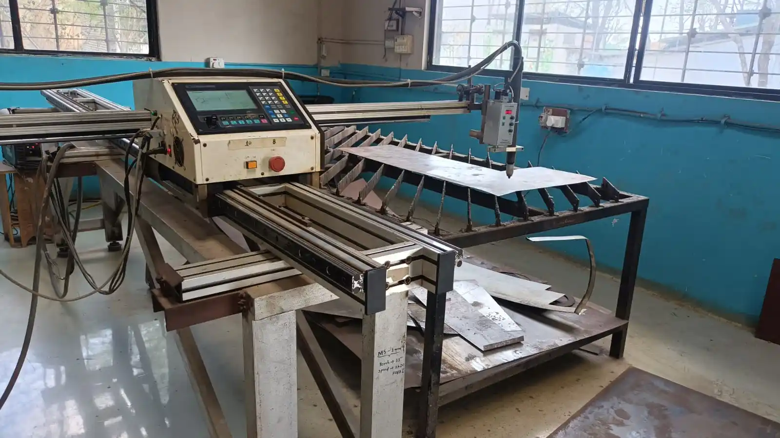
Plasma cutting is a process used to cut conductive metals like steel, stainless steel, aluminium, brass, and copper by using a hot plasma jet. It is commonly used in industries, vehicle repair, fabrication, and hobby projects.
In this process, compressed gas passes through a nozzle at high speed, and an electric arc creates hot plasma. The heat melts the metal, and the gas blows away the melted material to make the cut.
Plasma cutting can cut both thin and thick metal sheets. Hand plasma cutters can cut steel sheets up to 38 mm thick, while powerful CNC plasma cutters can cut up to 150 mm thick metal sheets. It is useful for straight, curved, and angled cutting with high accuracy.
Important Parameters which affecting Plasma Cutting
Kerf:
Kerf is the width of material removed during the plasma cutting process. It depends on cutting speed, amperage, and torch distance.
Cutting Speed:
Higher cutting speed makes a narrower kerf, while slower speed makes a wider kerf. Very high speed can stop proper cutting.
Cutting Amperage:
Increasing amperage makes the kerf wider and improves cutting power. Low amperage can reduce cutting quality and penetration.
Standoff Distance:
Standoff is the distance between the torch and the workpiece during cutting. A larger distance increases the kerf width and may reduce cutting quality.
Design digital process
Initially, I was confused about what to make using the plasma cutting machine. I wanted to create something useful. Then I saw the LED strip lights attached to my room wall and got the idea of making a table lamp. After that, I decided to design and make a table lamp for this week’s assignment because it would also be useful for me.
For the design, I used the Autodesk Fusion 360 software to create the 3D model of the table lamp.
I documented all the steps and the complete process I followed to create the design, as shown below.
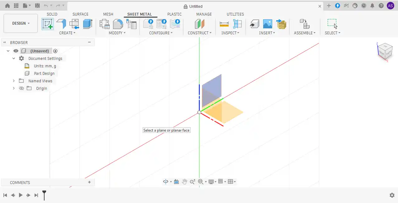
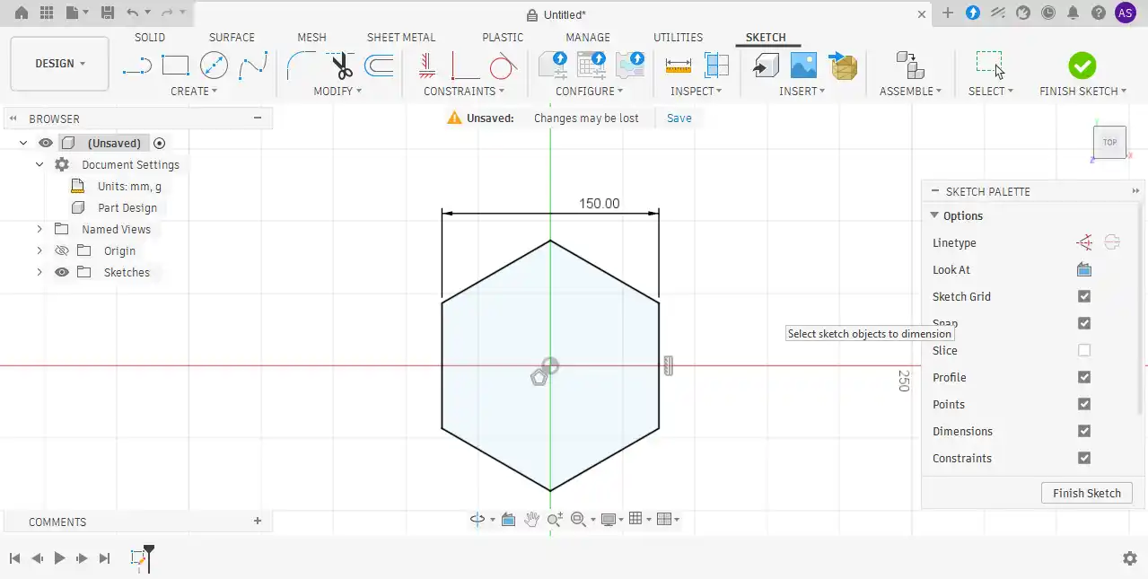
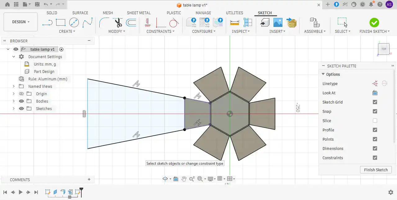
Step 1: First, I opened Fusion 360 and created a new project. After that, I switched to the Sheet Metal workspace and selected the required plane to begin the design process.
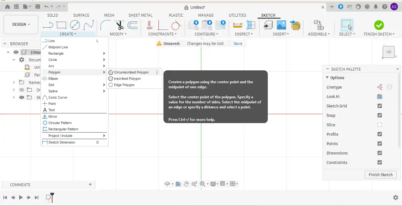
Step 2:Next, I went to the Create menu and selected the Polygon tool. Using the Center Polygon option, I created the shape from the center and applied the required dimensions.
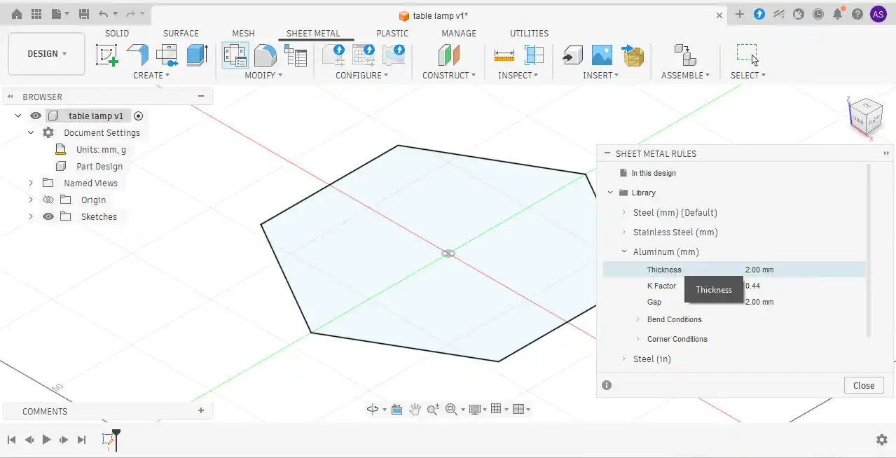
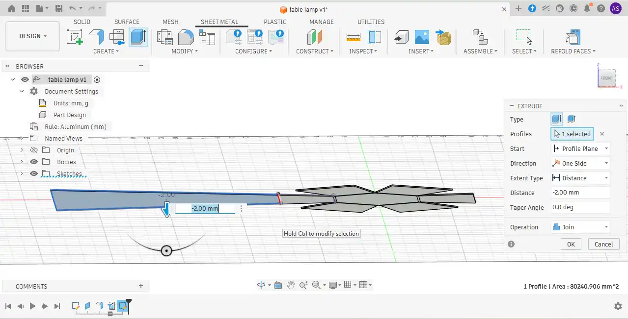
Step 3:After completing the sketch, the Extrude command was activated using the shortcut key “E,” and the entire sketch was extruded to a thickness of 2 mm.
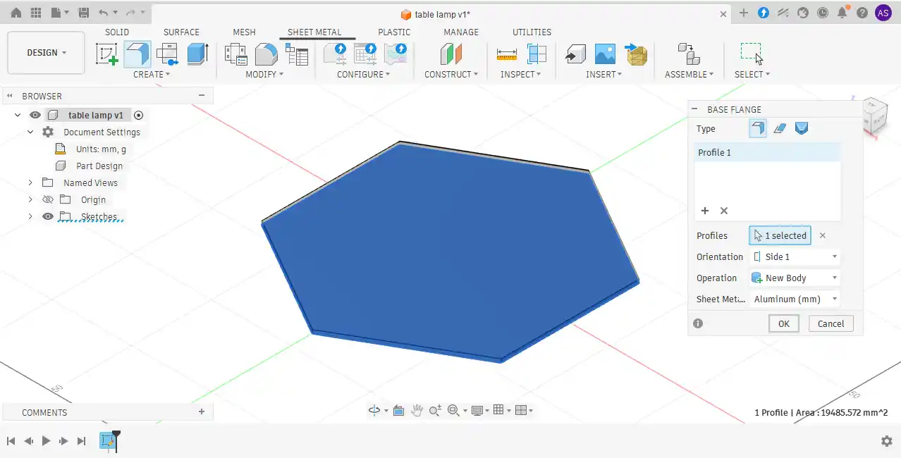
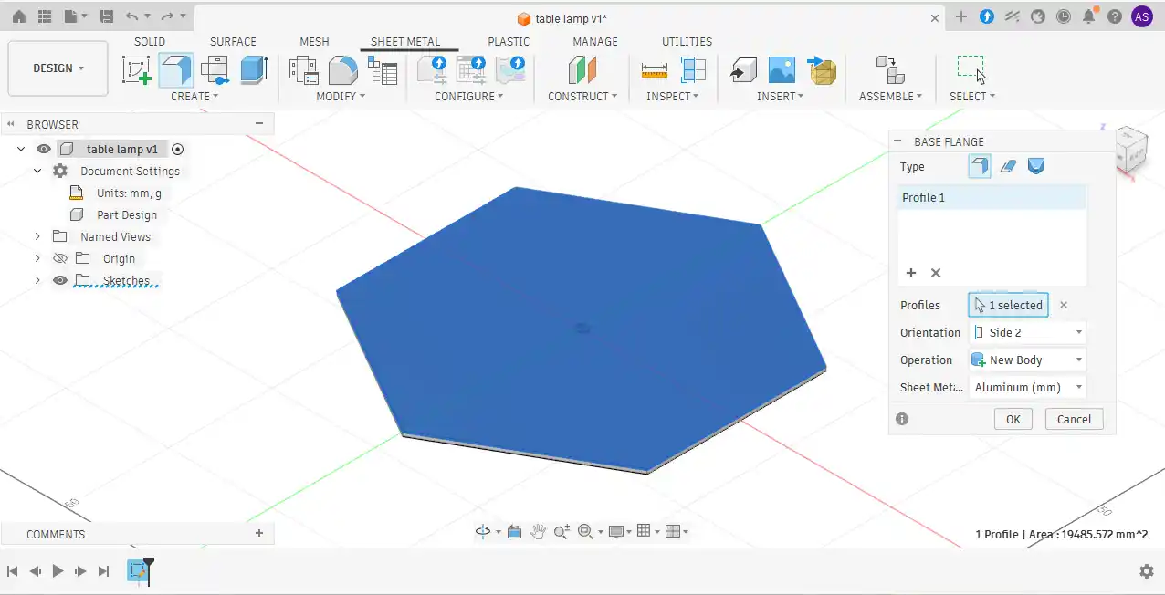
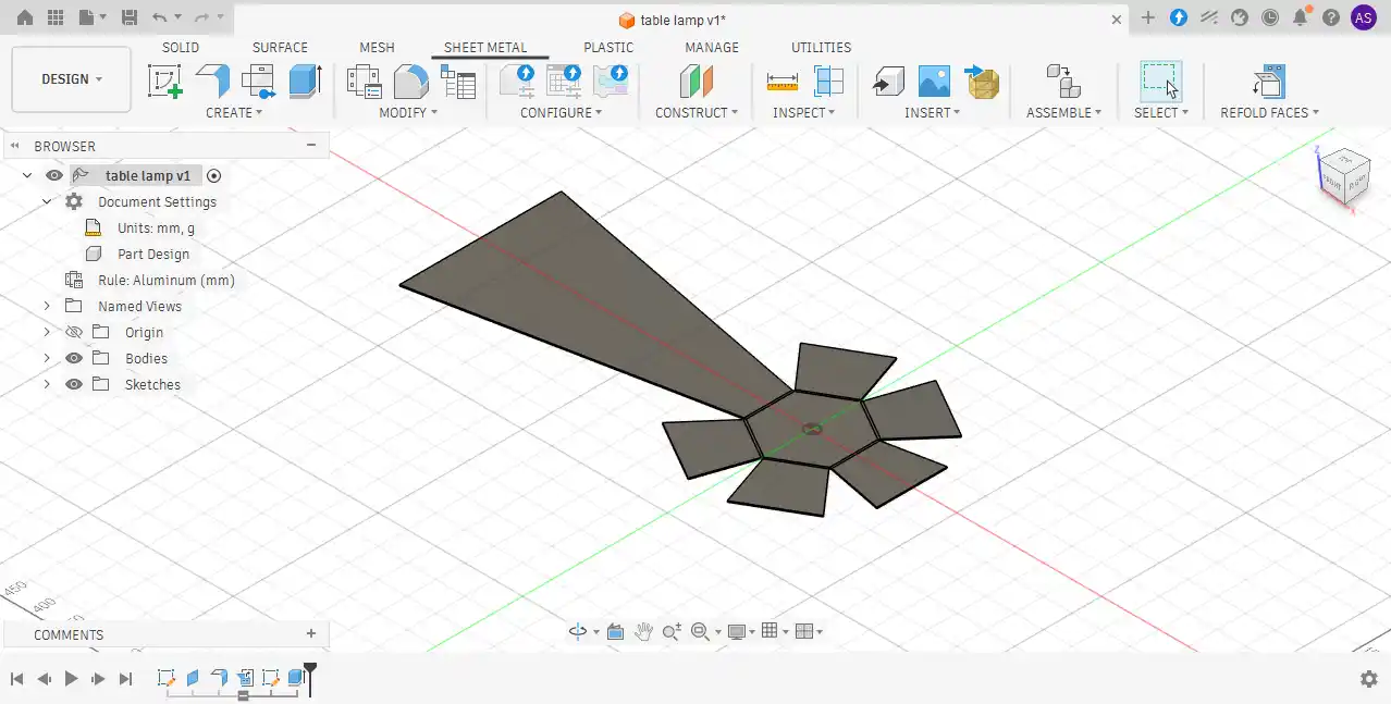
Step 4:In the next step, the required surface was selected, and the Base Flange tool was used to create a 100 mm flange.
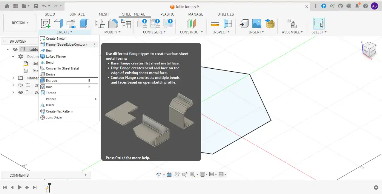
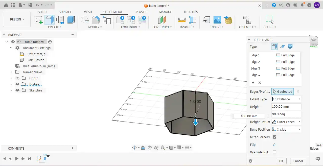
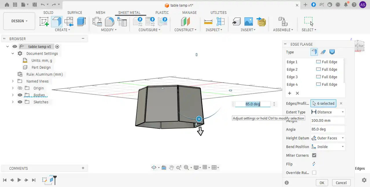
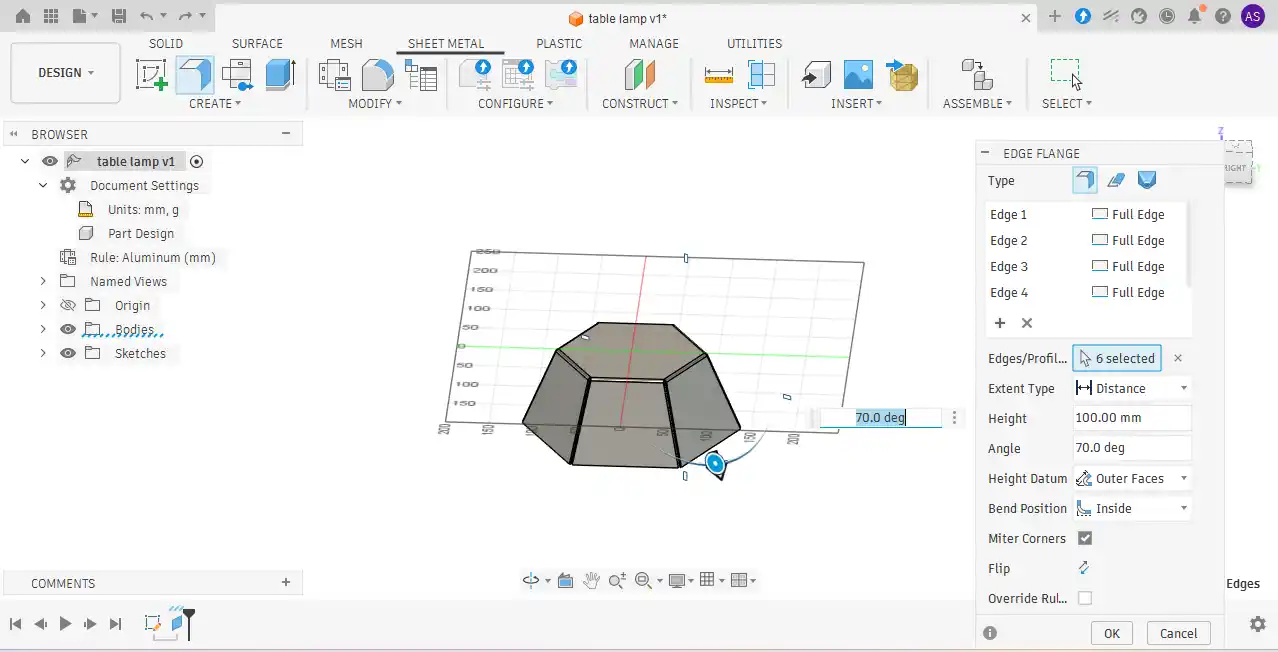
Step 5:While using the flange tool, I adjusted and checked the angle values to achieve the desired shape and appearance of the model.
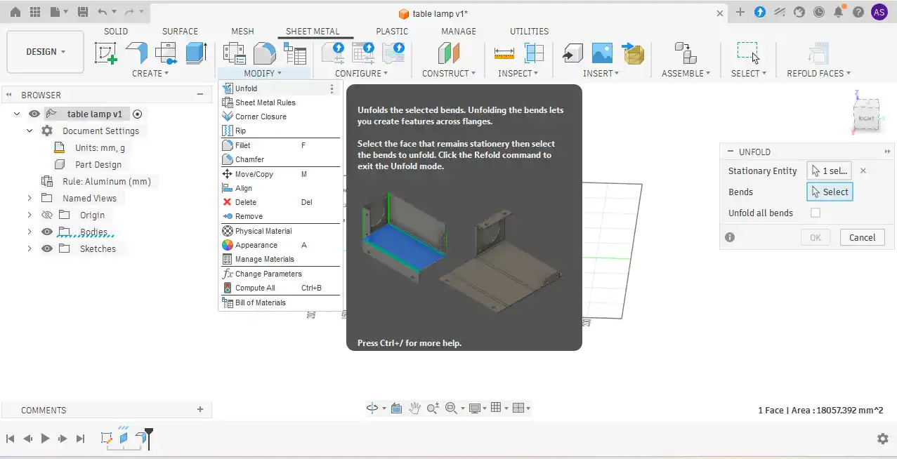
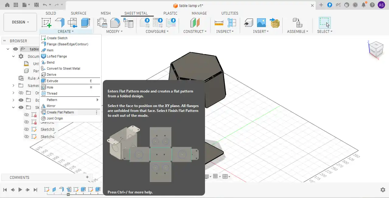
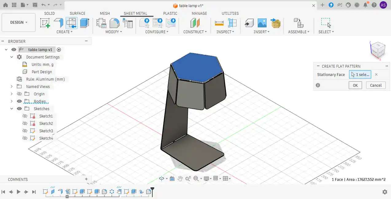
Step 6: Next, the sheet metal body was unfolded by selecting the appropriate face. After unfolding
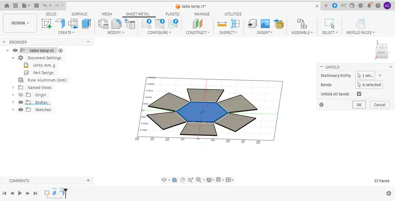
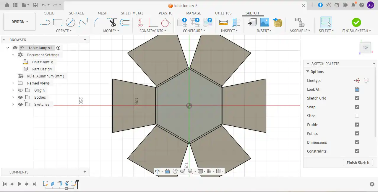
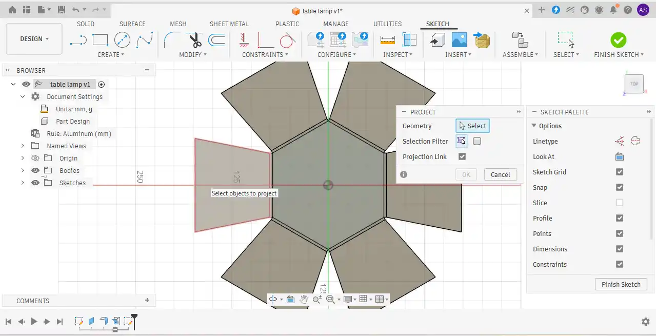
Step 7:a new sketch was created on the flat plate surface project geometry.
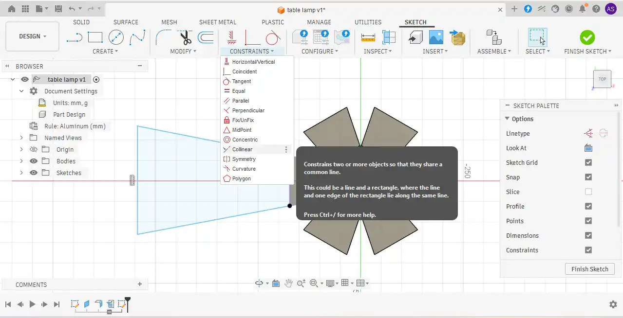
Step 8: Using the line tool, the required geometry was drawn, and constraints such as collinear and vertical constraints were applied to properly define the sketch.
Step 9: Using the line tool, the required geometry was drawn, and constraints such as collinear and vertical constraints were applied to properly define the sketch.
Step 10: After drawing the lines, dimensions were applied to specify the required line lengths and maintain accurate geometry.

Step 11: Once the sketch was completed, the Extrude command was activated using the “E” shortcut key. The selected sketch area was then extruded downward while maintaining the same thickness as the existing body.
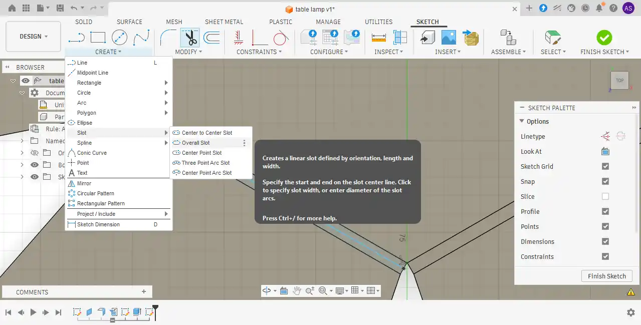
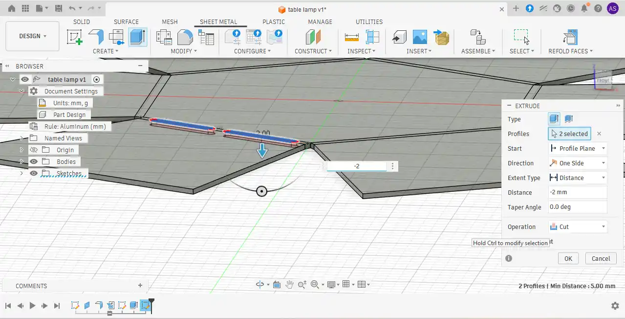
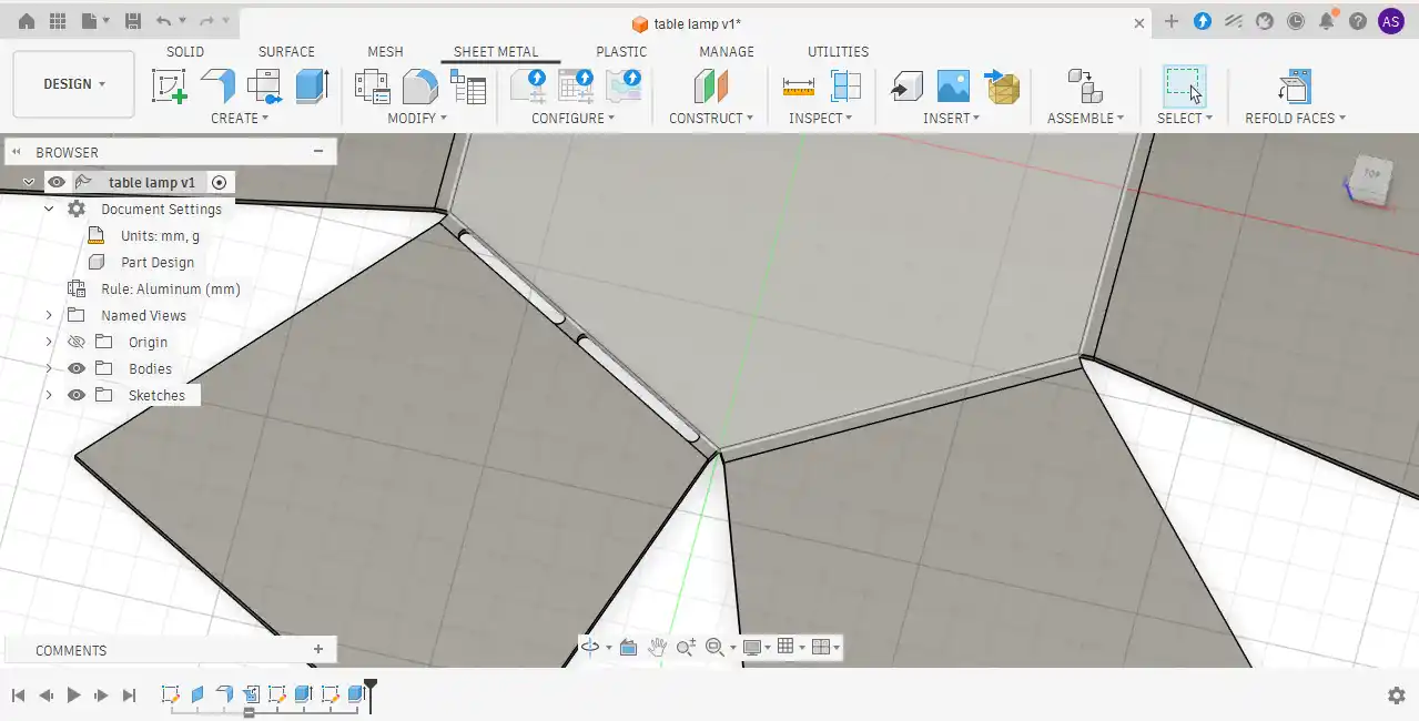
Step 12: After that, I wanted to create slots for easier bending of the sheet metal. First, I selected the surface and created a sketch with a center line using the Midpoint Line tool. Then, I went to the Slot option and selected the Overall Slot tool. After creating the slot shape, I selected the slot area and used the Extrude Cut operation to remove the material.
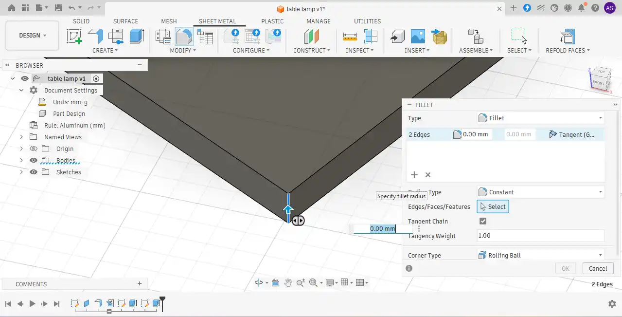
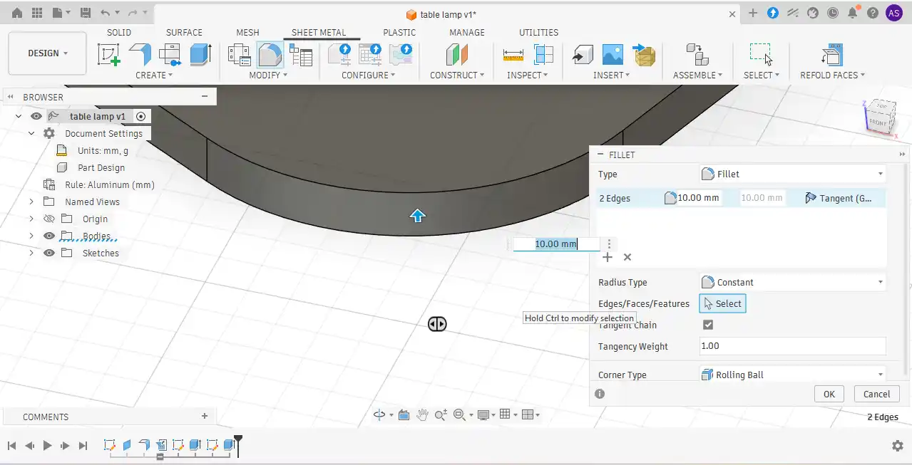
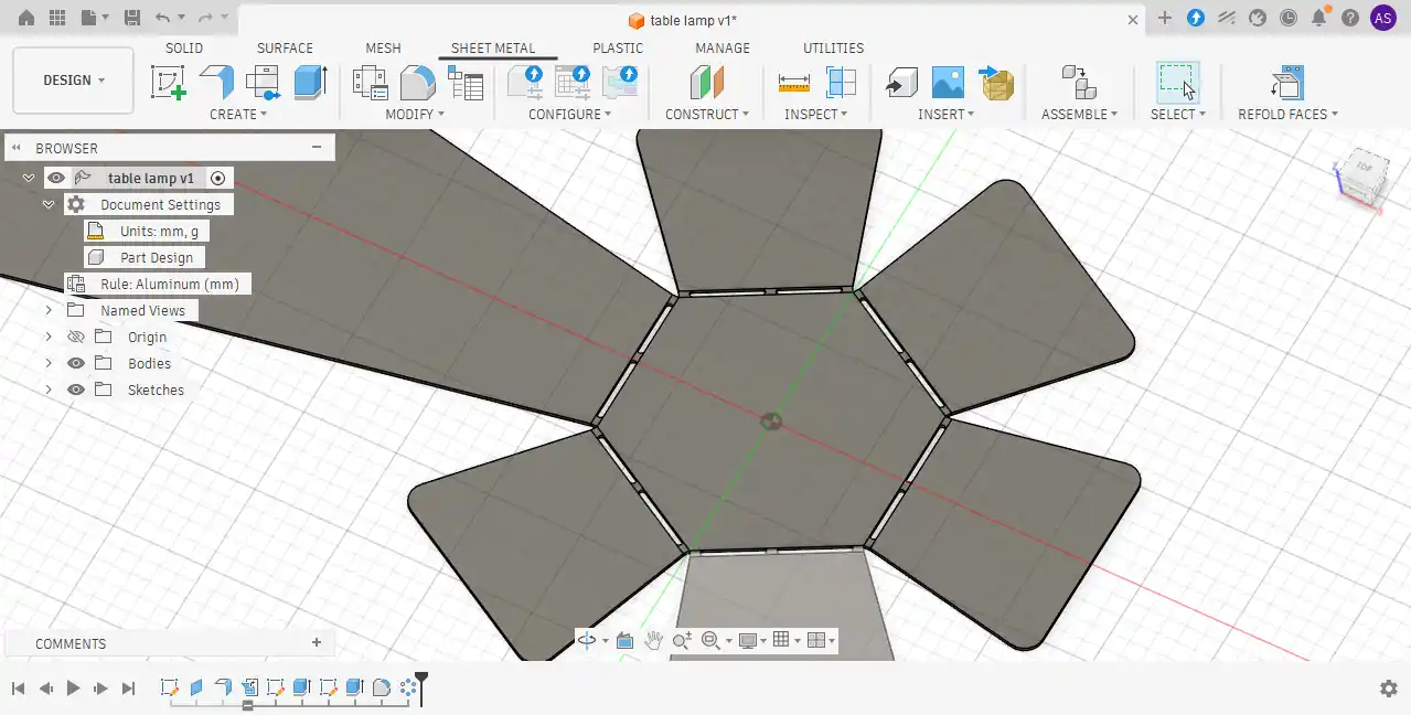
Step 13:The corner edges were selected, and the Fillet tool was applied to create smooth rounded corners.
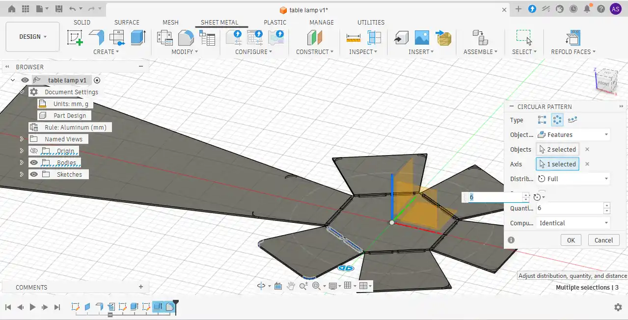
Step 14:To repeat the slot features and rounded corner edges around the entire body, the Circular Pattern tool was used.
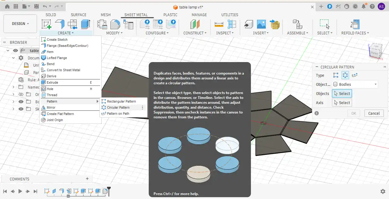
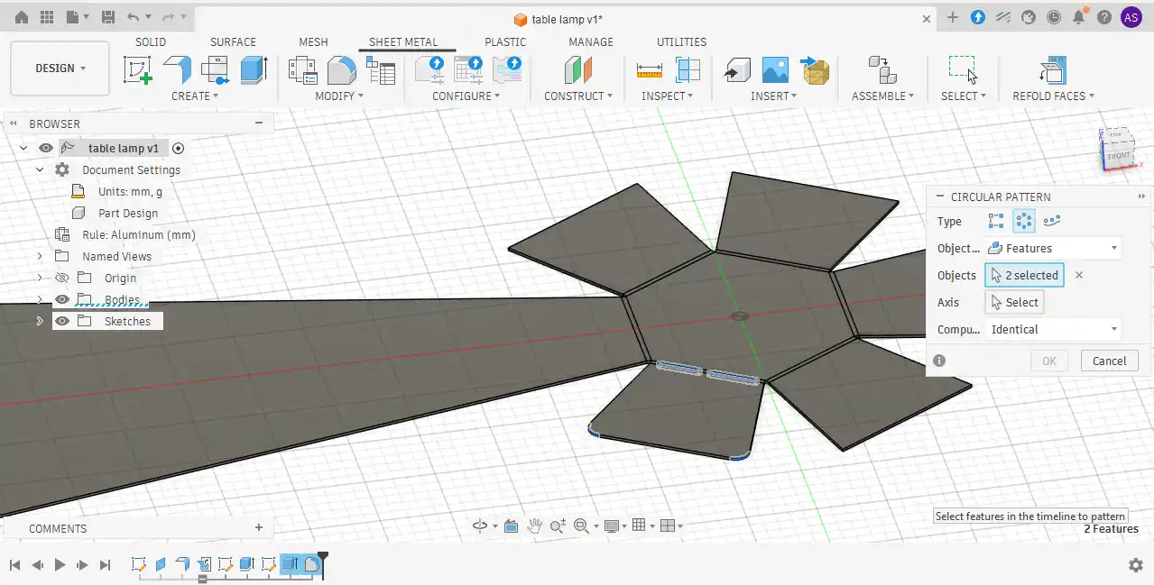
Step 15: While using the Circular Pattern tool, the central axis was selected to create repeated features evenly around the model.
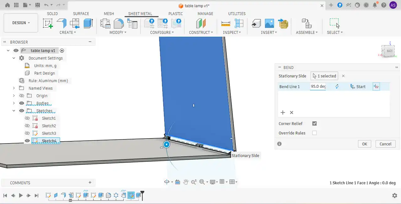
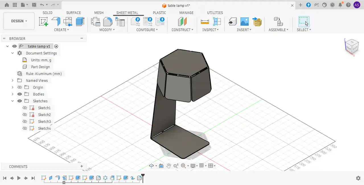
Step 16:In the final step, the Bend tool was used to form the stand structure and provide support for the complete body.
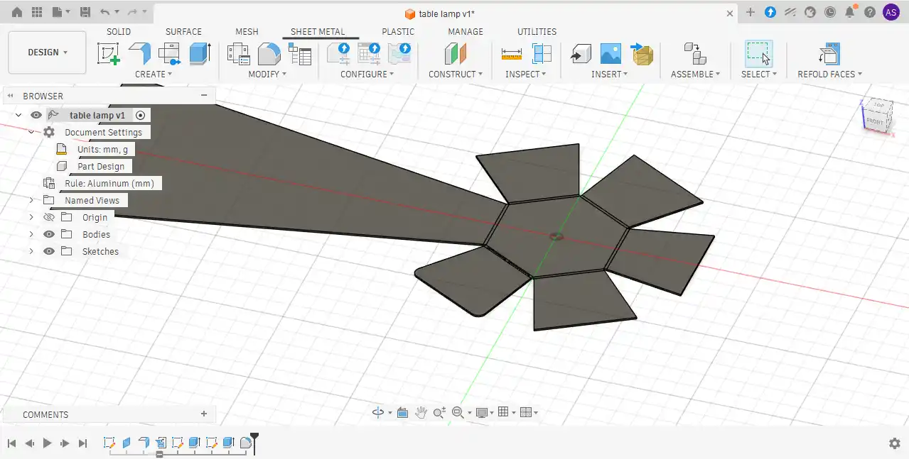
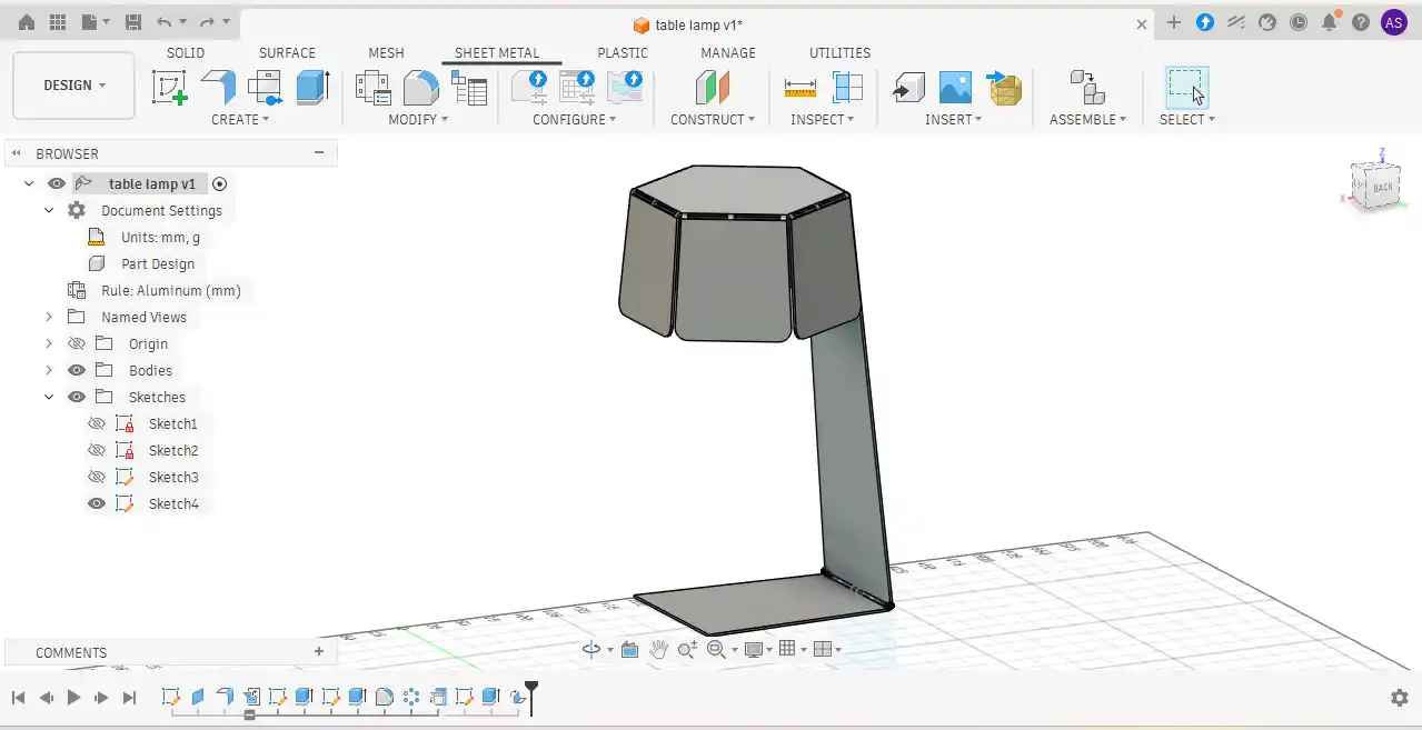
Step 17: The final version of the model looks like this.
Step 18: To prepare the design for plasma cutting, a DXF file was required for toolpath generation. The complete sheet metal assembly was first unfolded using the Unfold tool in Fusion 360. After unfolding the model.
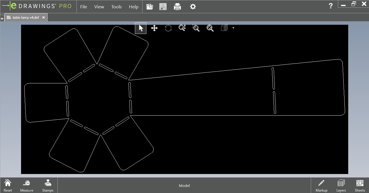
Step 19:the flat pattern was exported in DXF format, which was later used for plasma cutting and machining operations.
Tool path
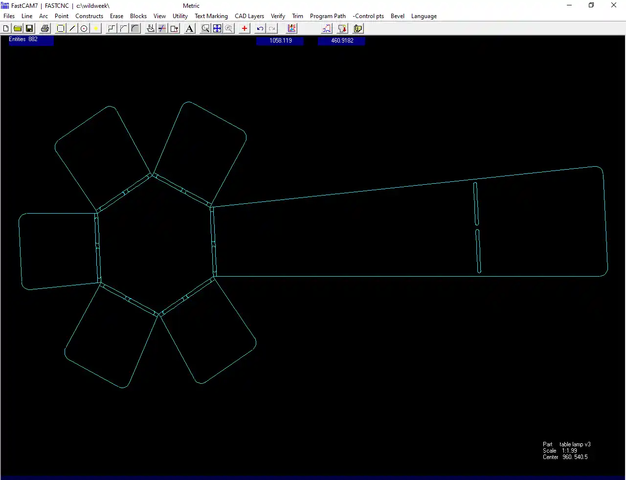
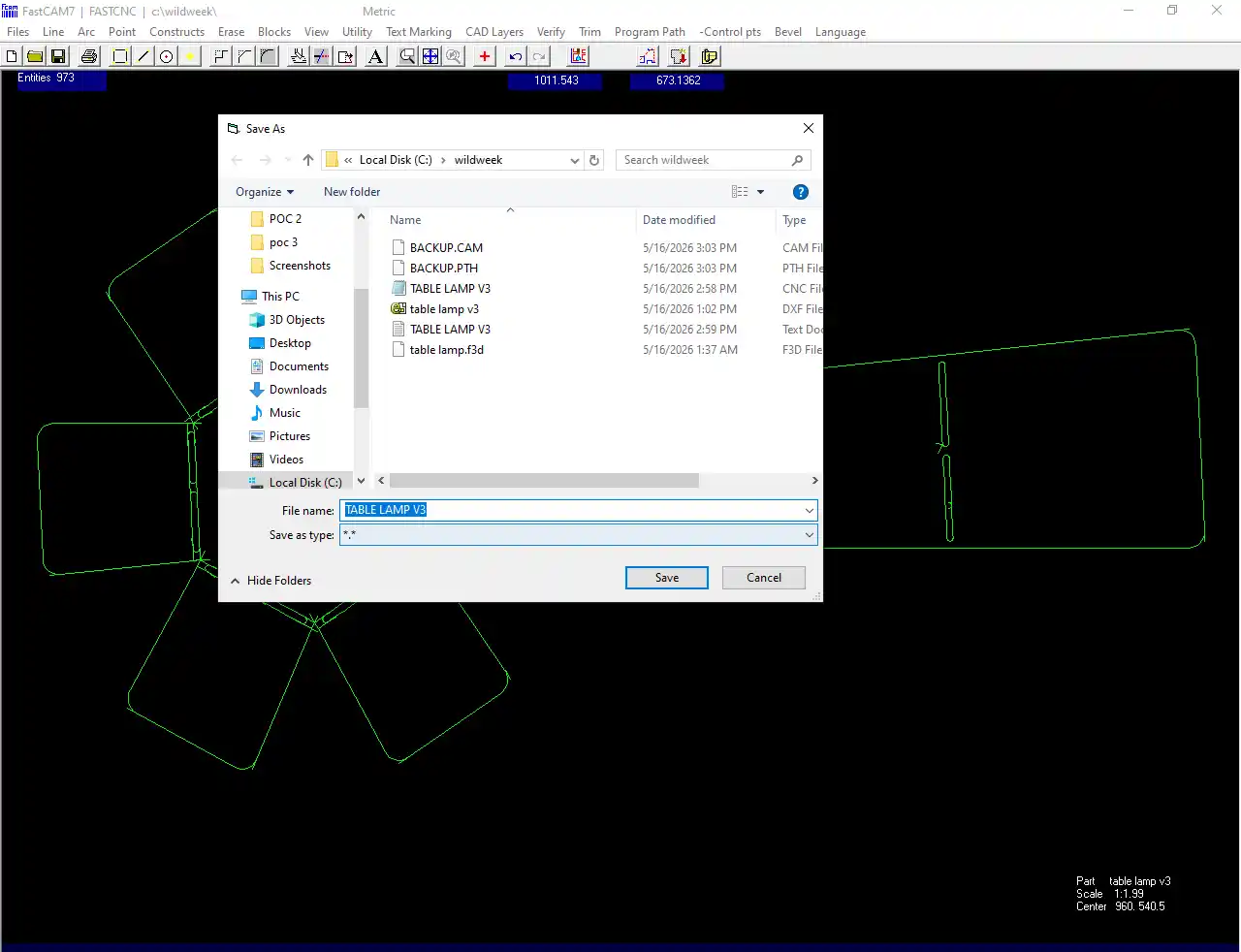
Step 1:The plasma cutting toolpath was generated using FastCAM7 software. After exporting the unfolded design as a DXF file from Fusion 360, the file was imported into FastCAM7. The required cutting settings and machining toolpaths were then configured for the plasma cutting operation.
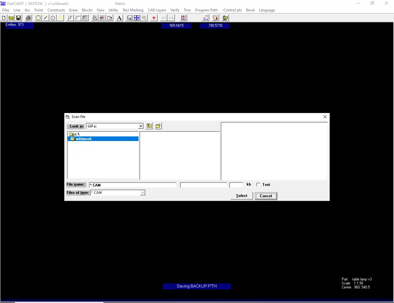
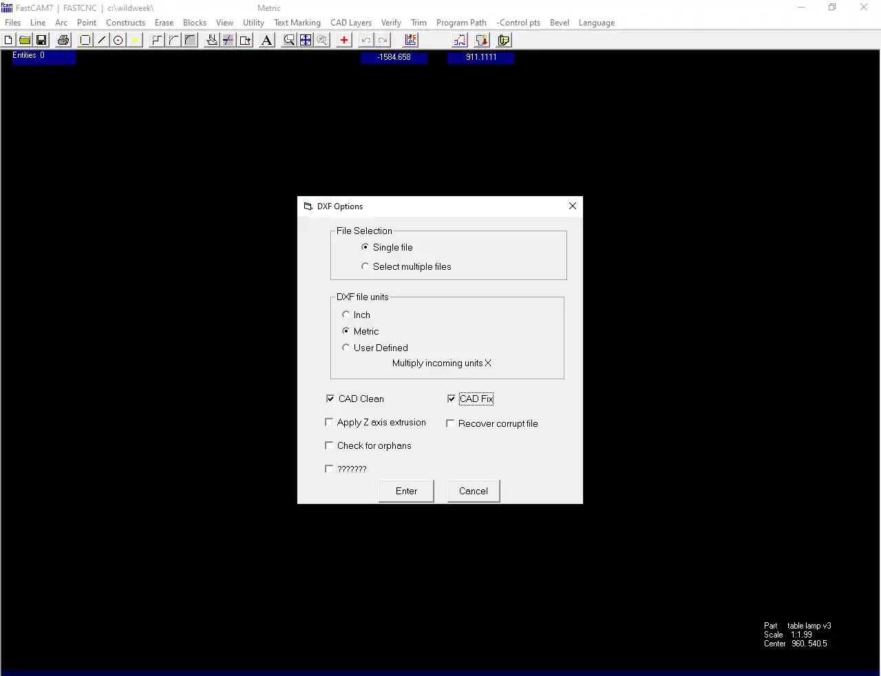
Step 2:After importing the file, I again went to the File menu and selected the DXF Restore option. A new window opened showing options such as Single File Selection and DXF Unit Matrix. Then, I clicked CAD Clean and CAD Fix to remove errors and correct the design file. Finally, I pressed the Enter button to apply the settings.
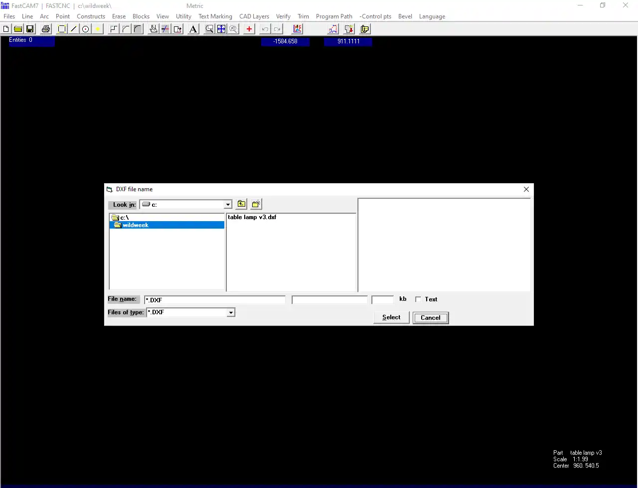
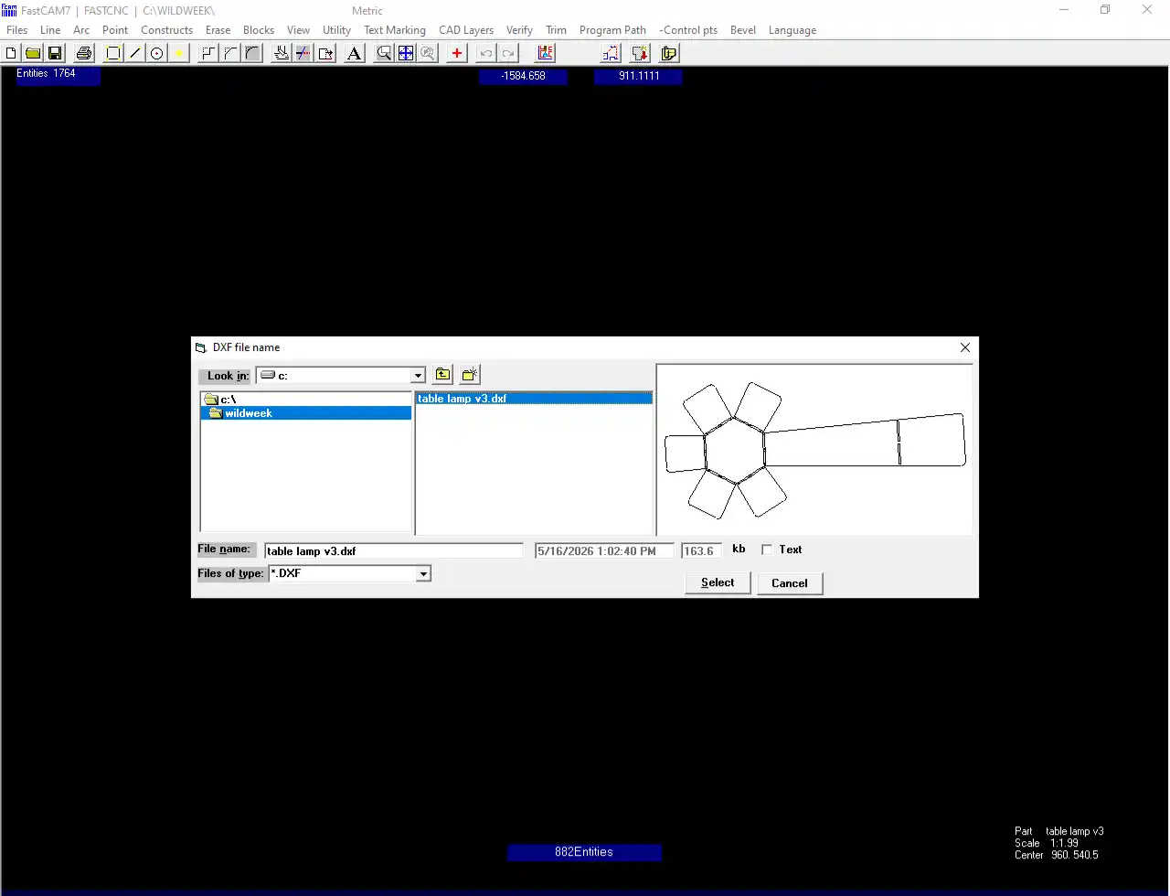
Step 3:After opening the new window, I browsed to the folder where the DXF file was saved and selected the required file. The file selection window displayed only DXF files, making it easier to choose the correct design file for the next process.
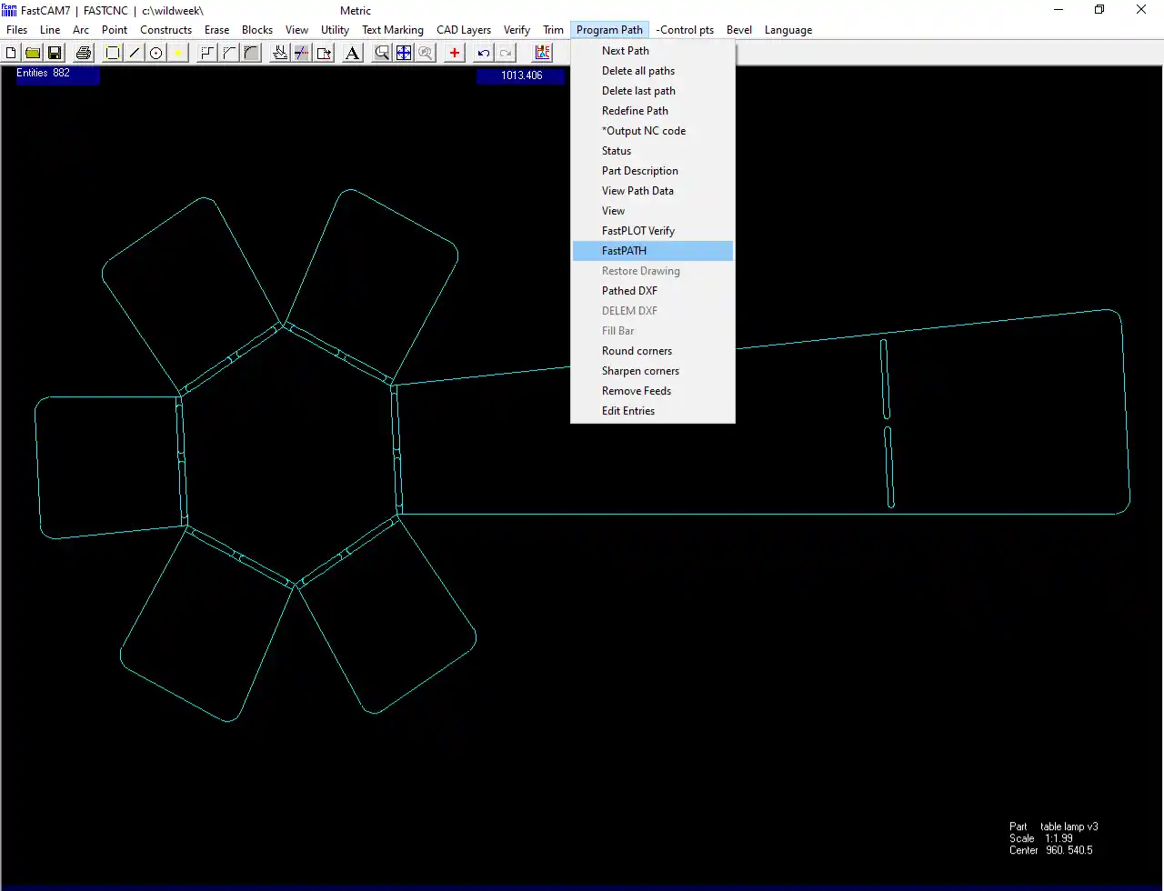
Step 5:After importing the DXF file successfully, I navigated to the Program Path menu and selected the Fast Path option for toolpath generation. Finally, the settings were confirmed to proceed to the next step.
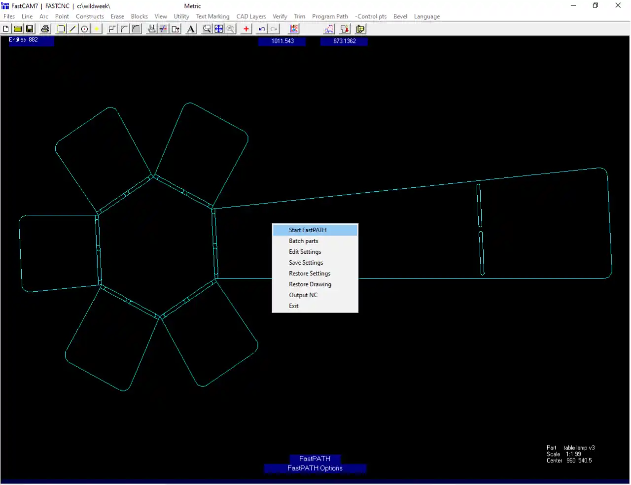
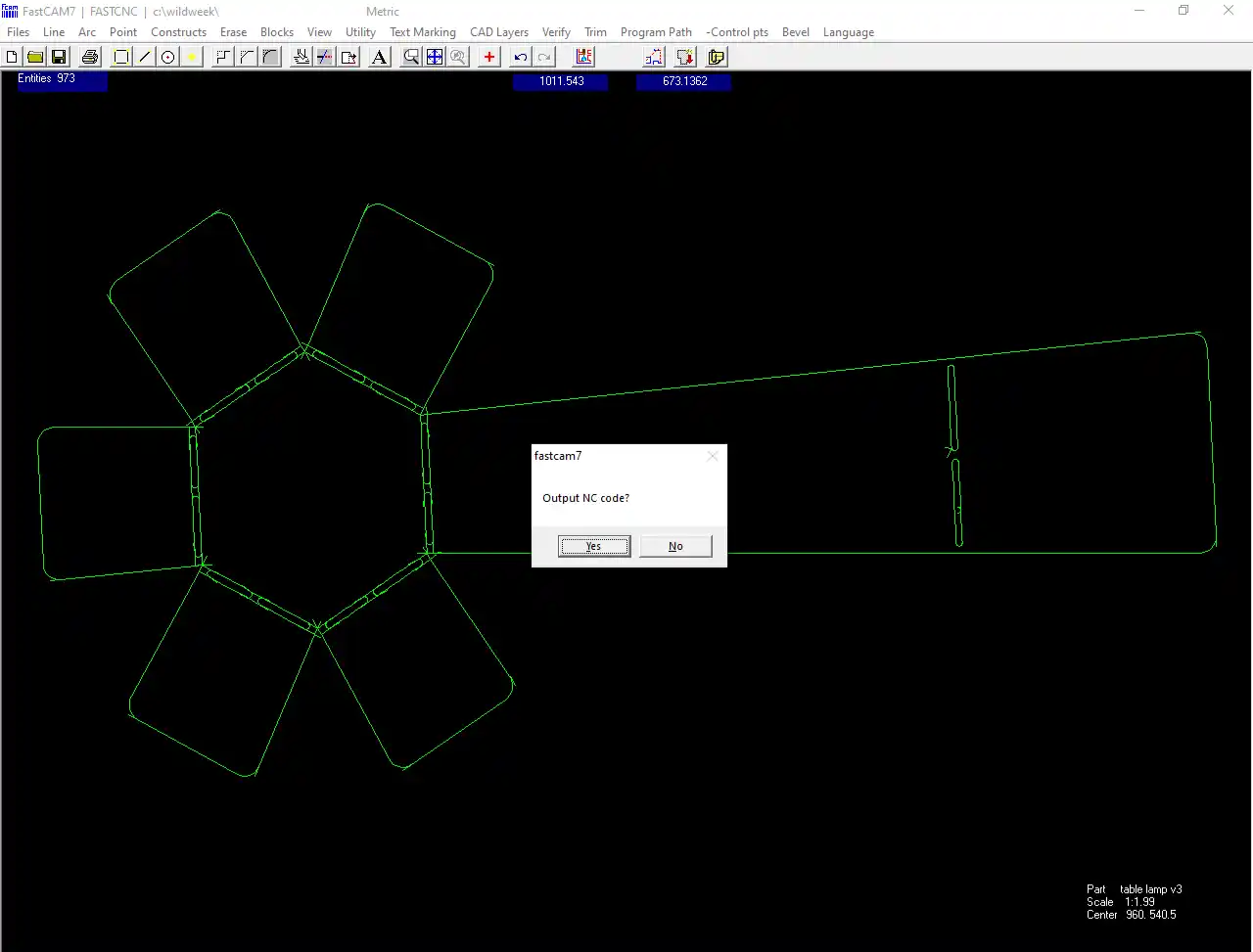
Step 7:Then a new window appeared. I clicked on "Start Fast Path". After opening the next window, the software generated the output NC code, and I selected "Yes" to continue. Finally, the toolpath was generated successfully.
Step 9: Finally, the file was saved in TXT format because the machine reads the TXT G-code file for operation. After saving the file successfully, it was ready for the cutting process. The pen drive was then connected directly to the machine to transfer the file for the cutting process.
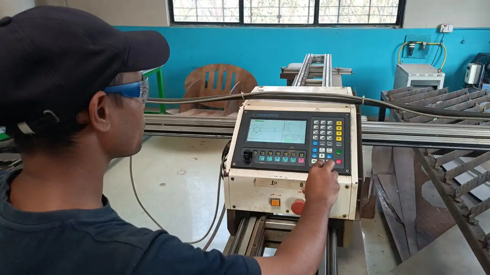
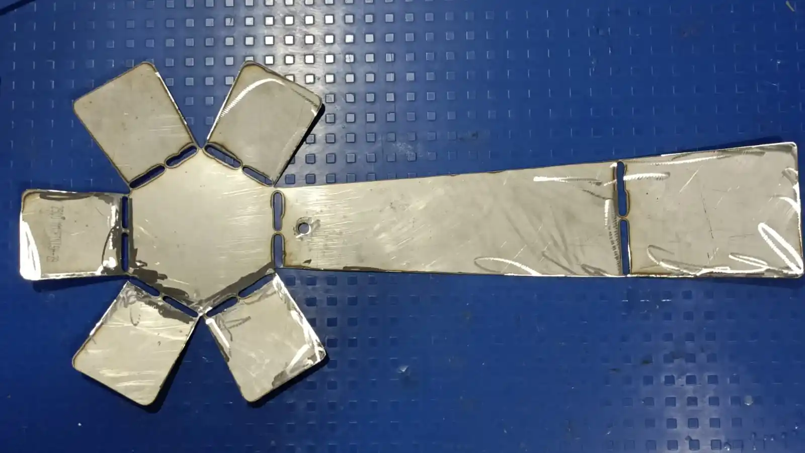
Fabrication: Before starting the machine, I set up the metal sheet on the machine bed and adjusted it according to the design area. After positioning the sheet properly, I started the machine to begin the cutting process.
After setting the metal sheet, I turned on the machine and connected the pen drive to it. Then, I selected the required file from the pen drive. I also adjusted the nozzle position properly before starting the cutting process.
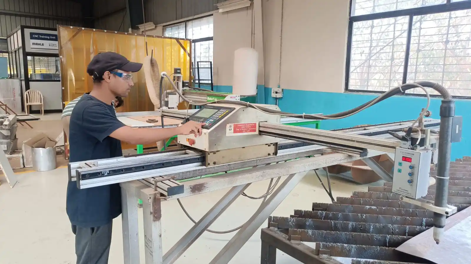
In the next step, a dry run was performed before actual cutting to verify the movement of the machine and check the working area coverage according to the design dimensions.
The plasma cutting parameters were adjusted according to the thickness of the sheet metal material. The plasma power and air compressor settings were configured appropriately. Before starting the operation, all safety checks were performed to ensure safe machine operation, and then the cutting process was started.
During the machining process, I continuously monitored the machine operation to ensure the cutting was performed correctly and the job was completed without any issues.
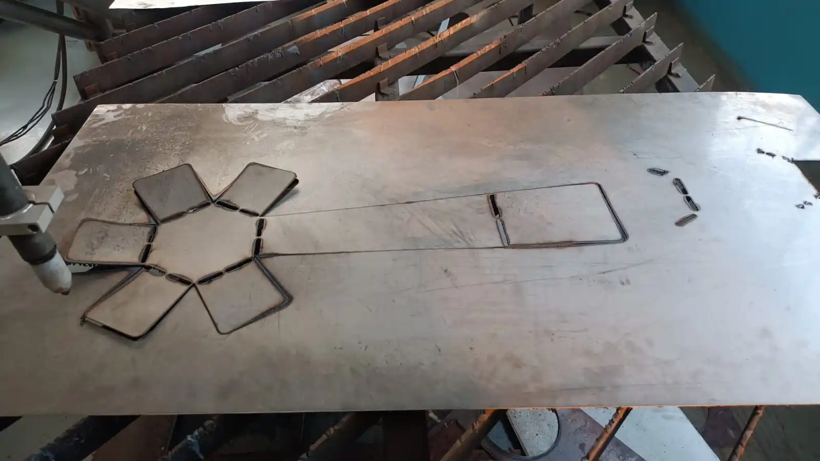
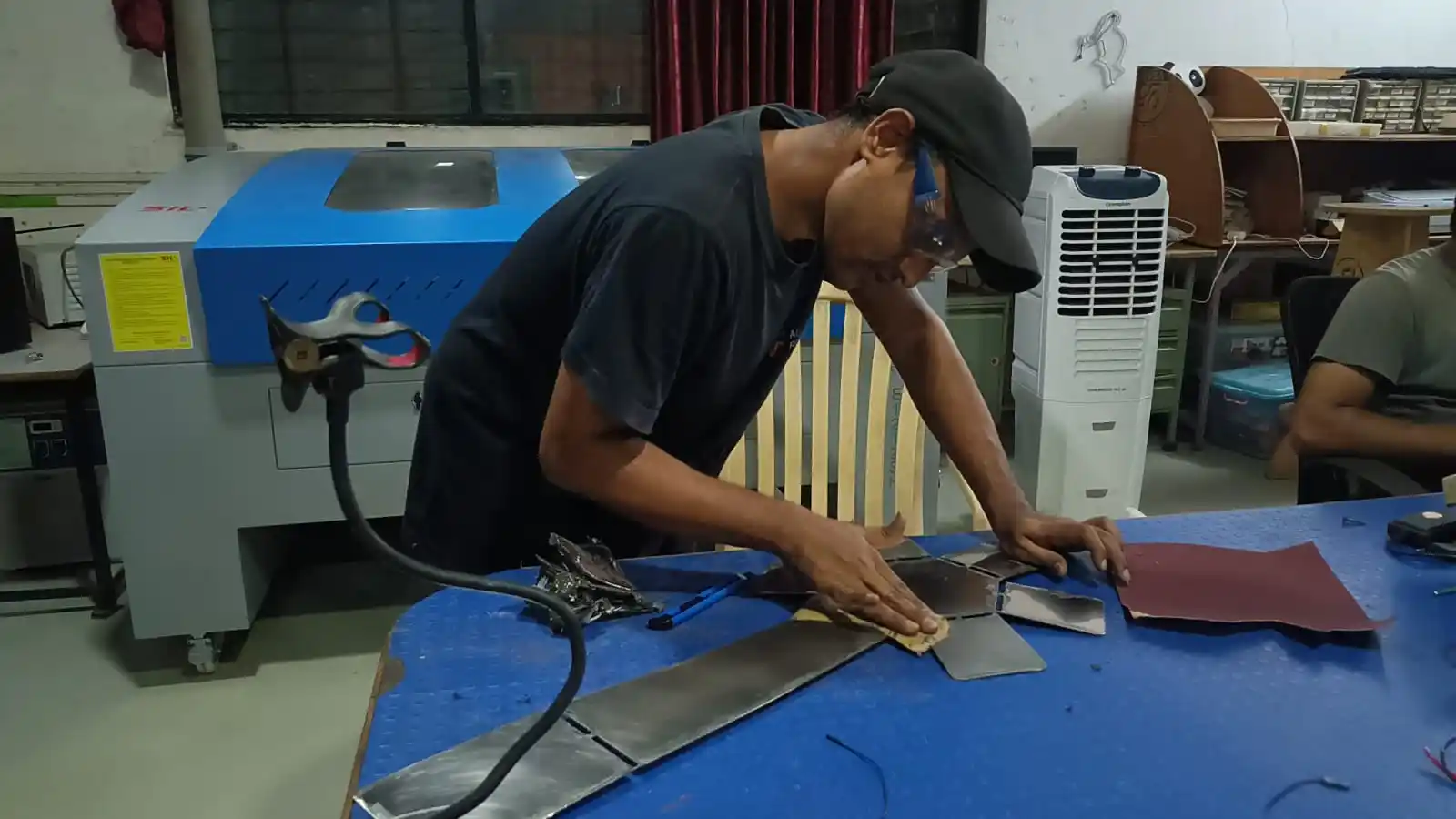
After the cutting process was completed, post-processing and cleaning were required because burnt metal residue and rough edges were formed during plasma cutting. A metal grinder was first used to remove excess material and clean the edges. Then, sandpaper was used to smooth the surface and eliminate any sharp edges for a better finish.
After the finishing process was completed, the painting process was carried out using spray paint. Two coats of paint were applied to improve the surface appearance and protection. The first coat was applied and left to dry for 4–5 hours. After drying, the surface was lightly sanded using fine-grit sandpaper before applying the second coat for a smoother finish.
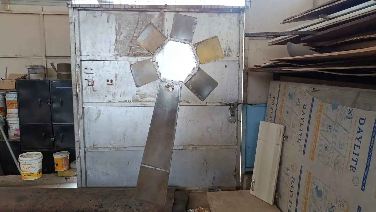
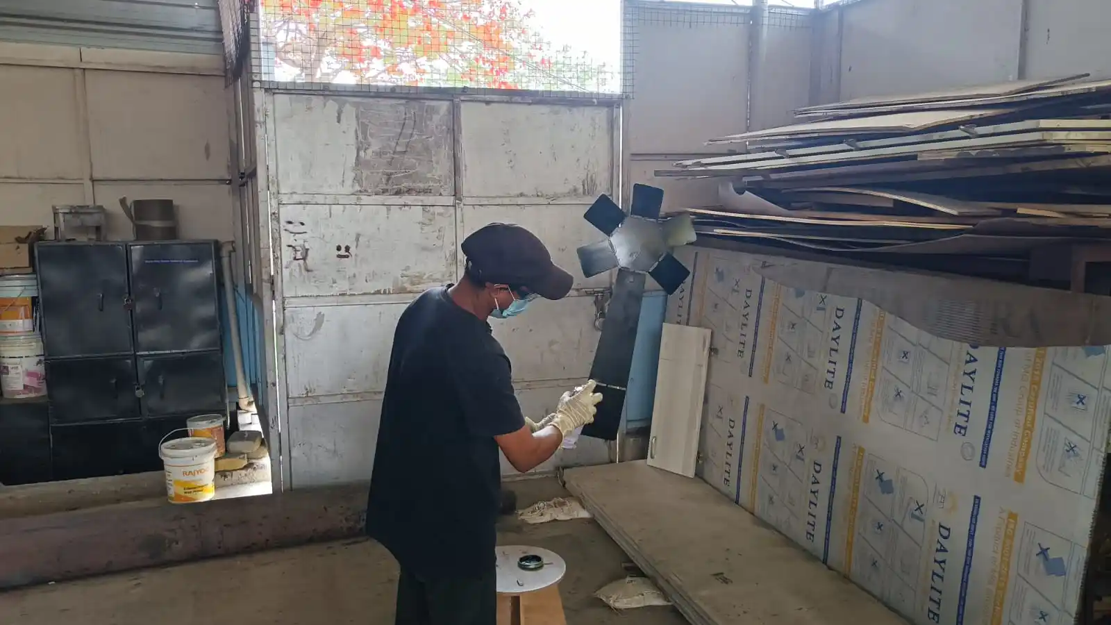
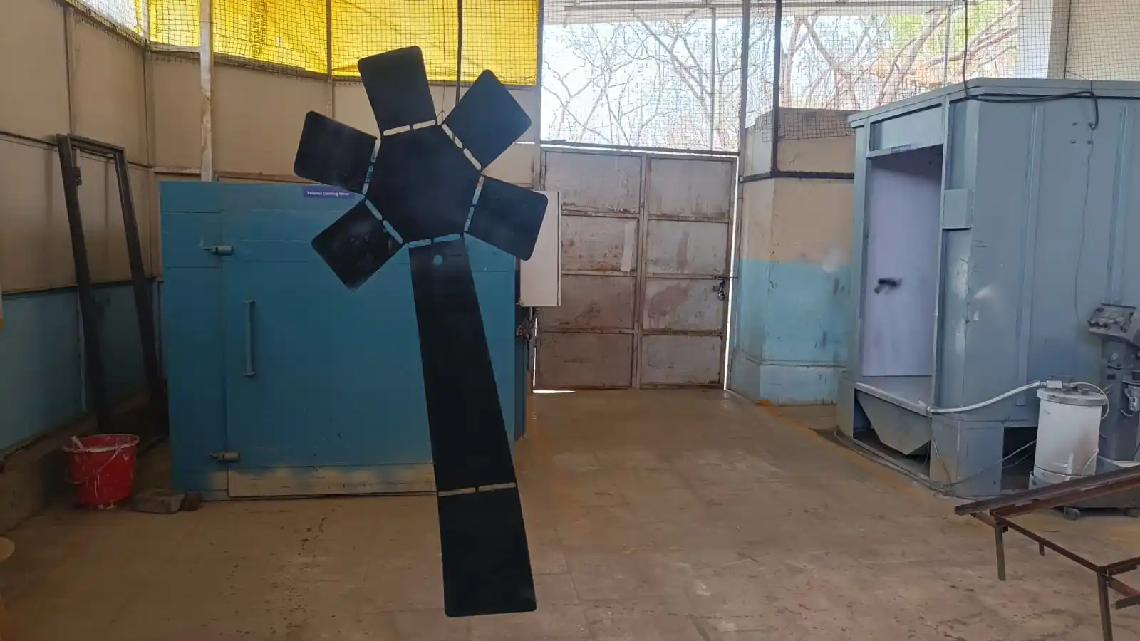
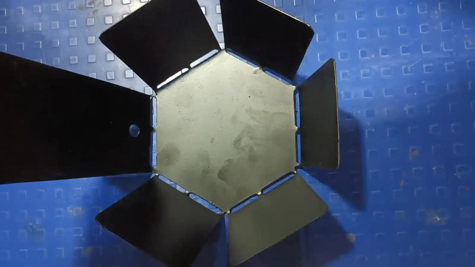
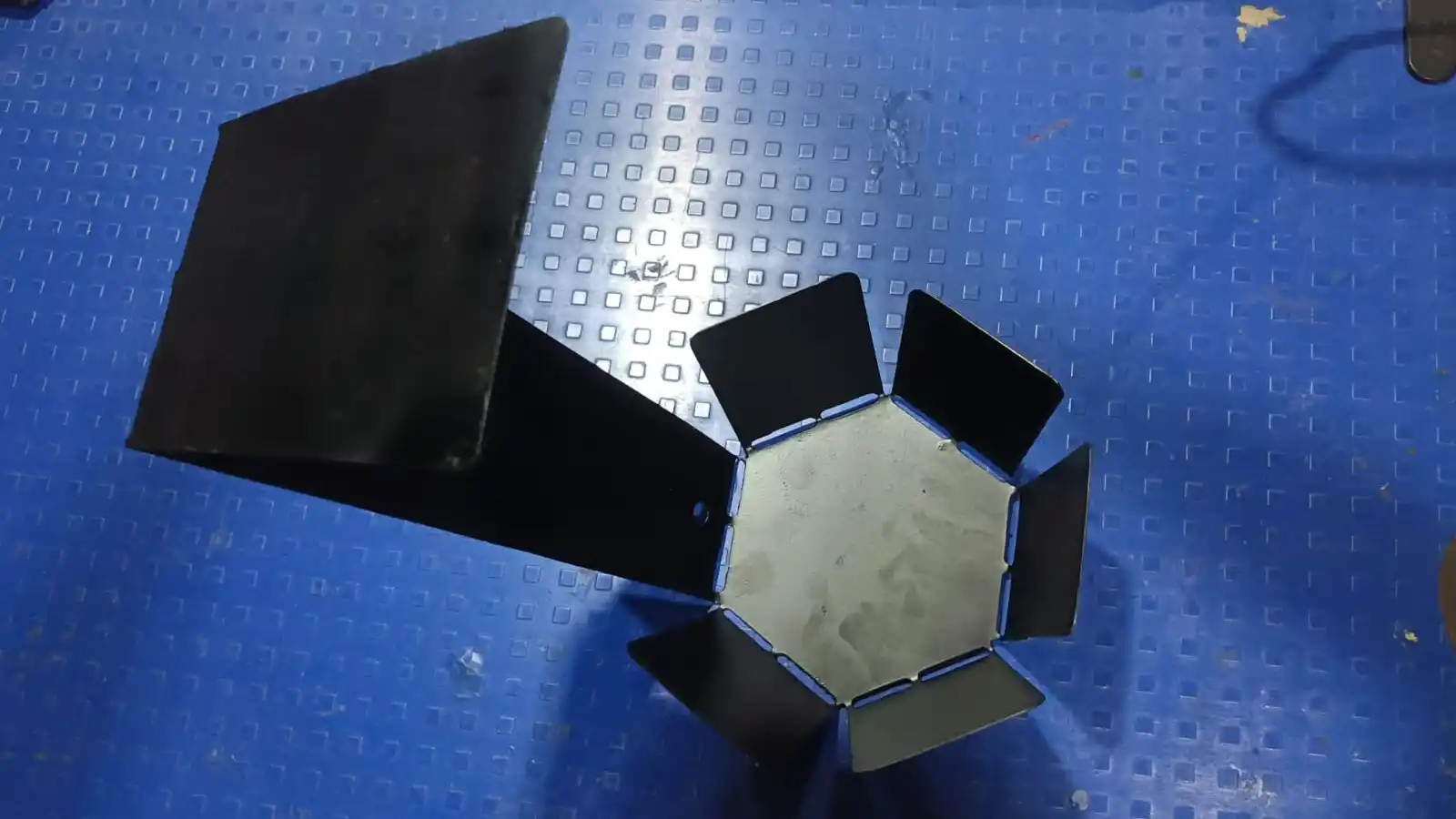
After completing the painting process, the sheet metal part was bent according to the required design shape. During the bending process, the component was inspected for any dents, deformation, or paint removal to ensure proper quality and finishing.
In the next step, I attached the LED strip to the structure. For the power supply connection, I soldered a power jack because the LED strip operates on 12V.
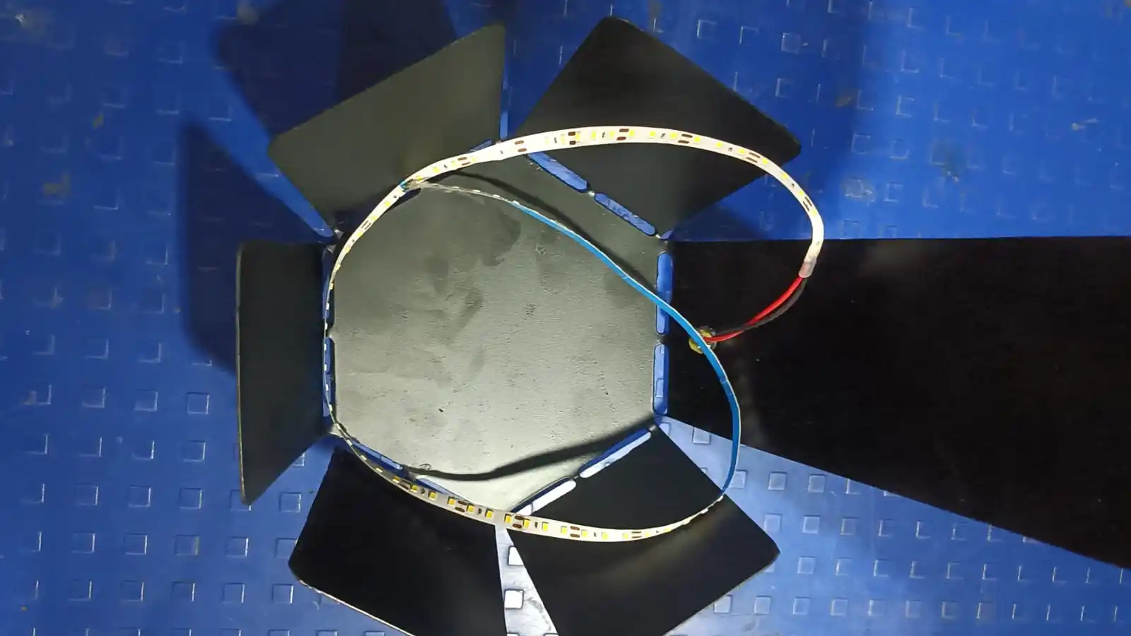
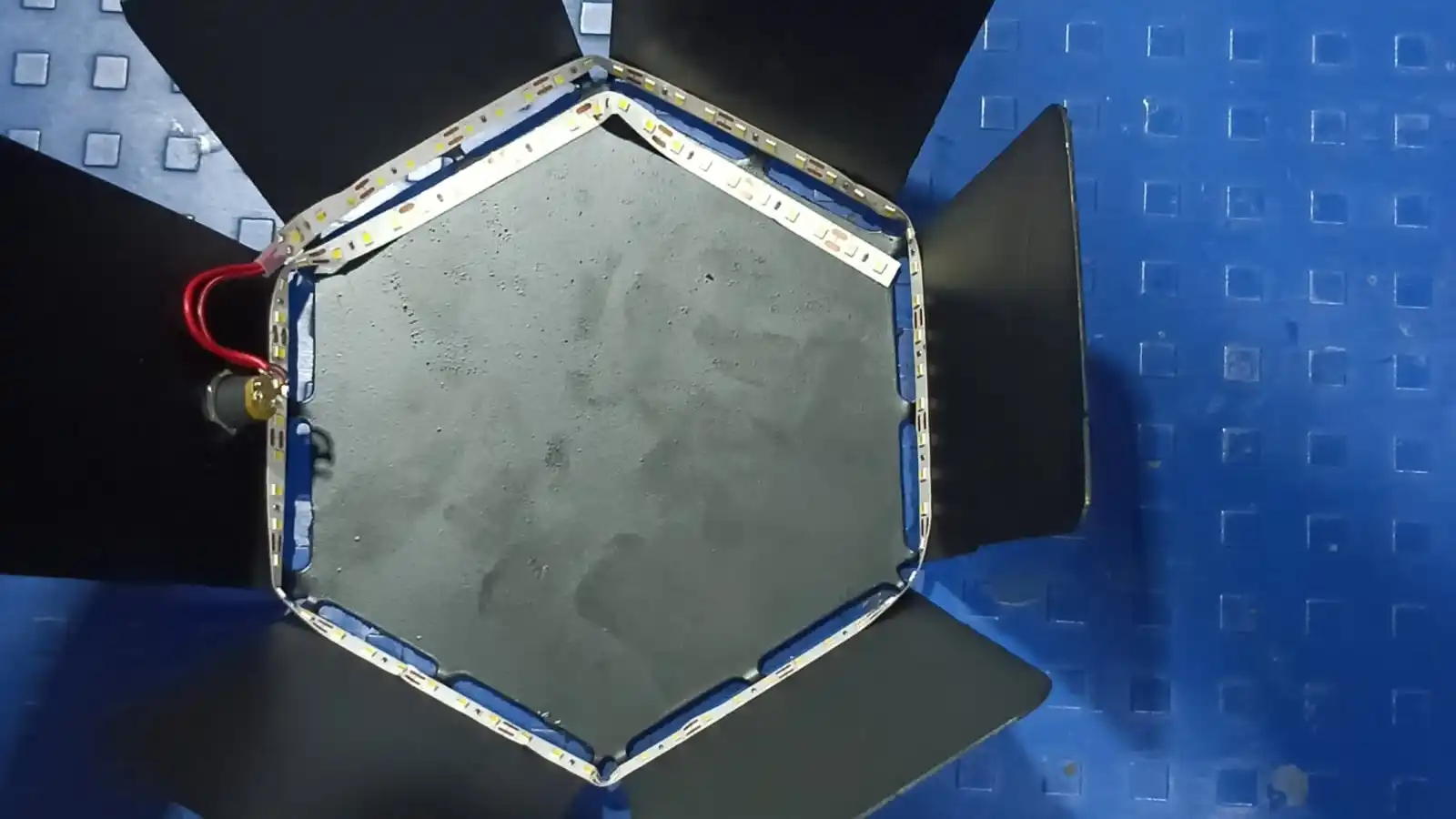
After that, I checked whether the LED was turning ON and OFF properly to verify that the circuit and power connections were working correctly.
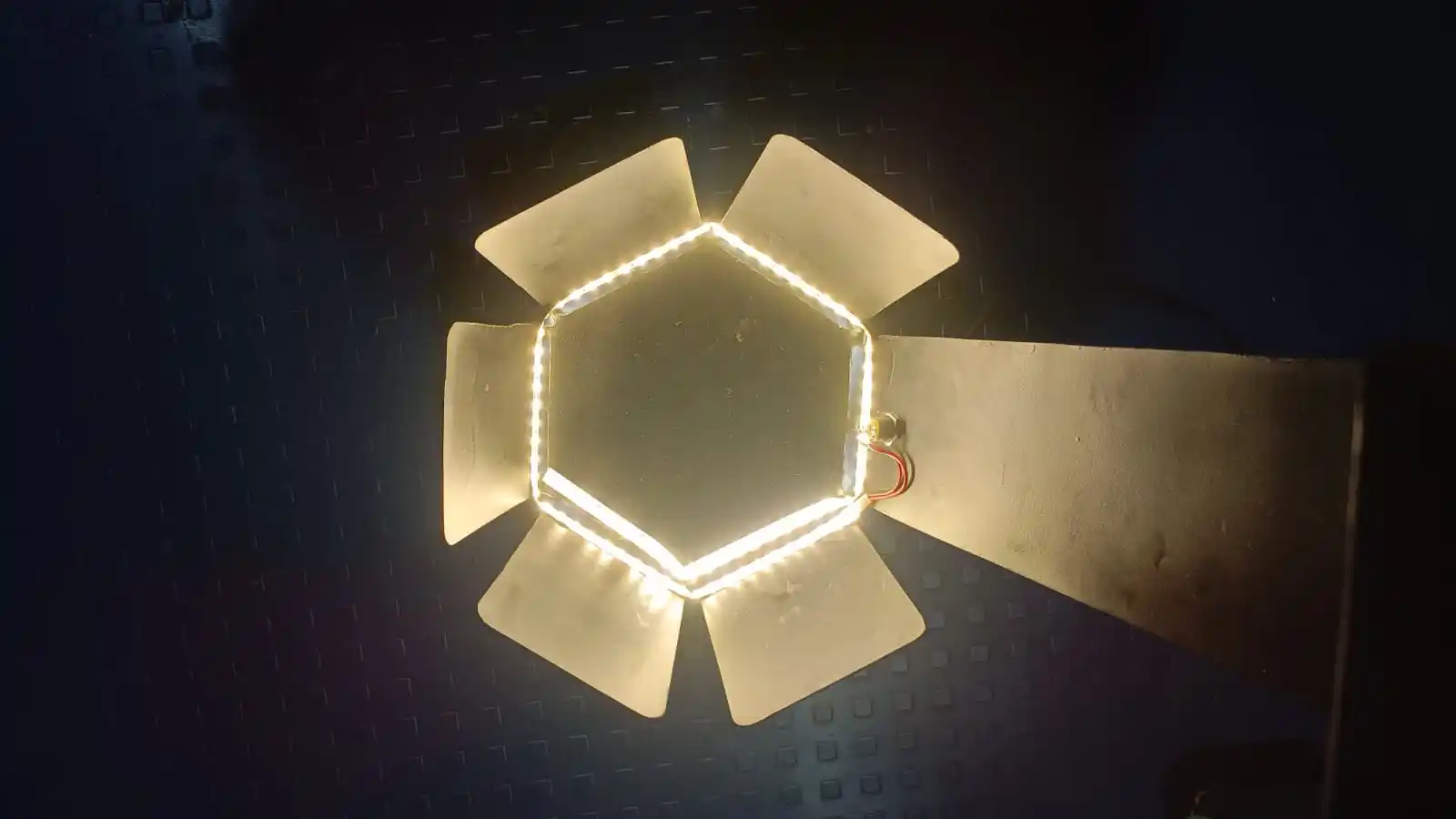
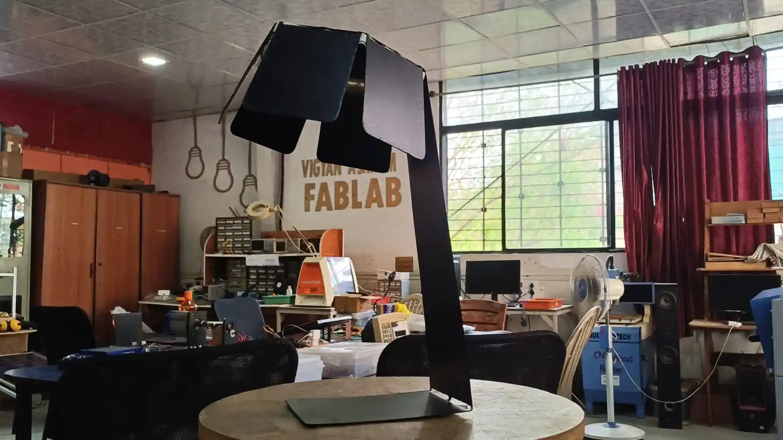
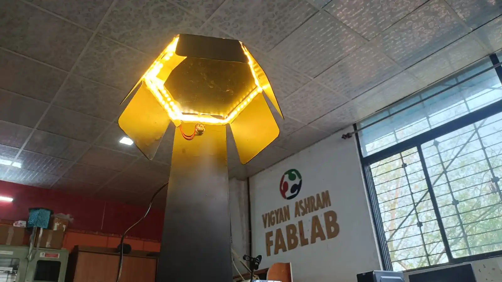
The LED light was very bright, so I diffused the light using tape to reduce the intensity and make it softer. After completing the setup, I captured some hero shots of the final product.
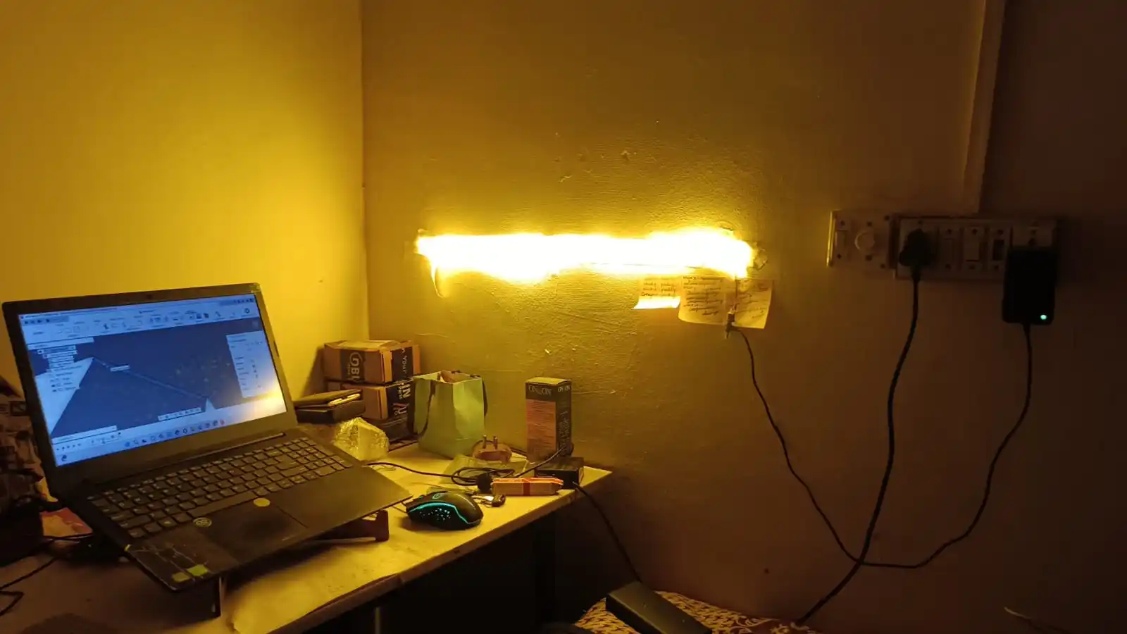
Before this project, my room with the LED strip looked like this.
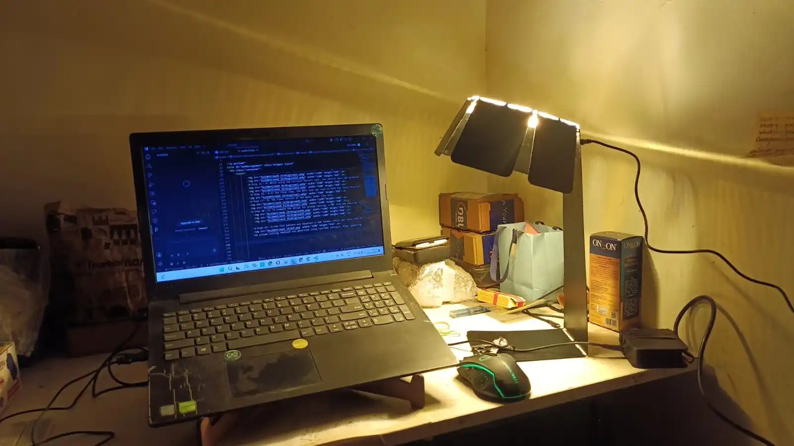
After setting up the table lamp in my room, my room looked like this.
Problems Faced:
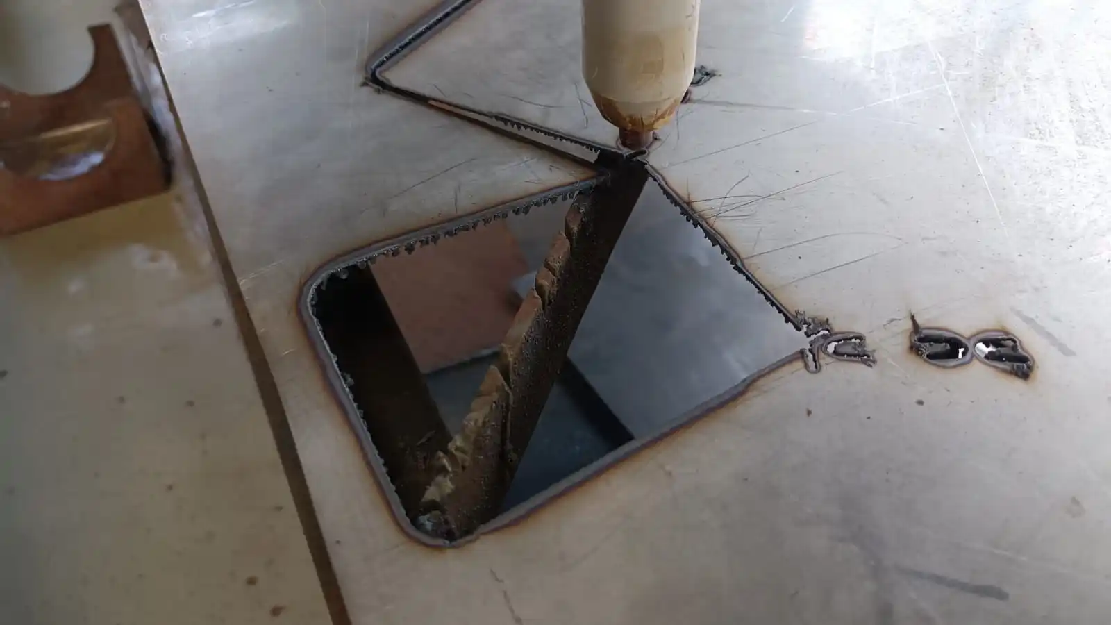
1) During the DXF export process, I faced some issues with the file. Because of this problem, the cutting path was not generated correctly, and some parts of the design were completely cut during the machining process.
2) During the second attempt, the sheet metal moved slightly during the cutting process. Because of this, I adjusted and fixed the sheet properly before continuing the operation.
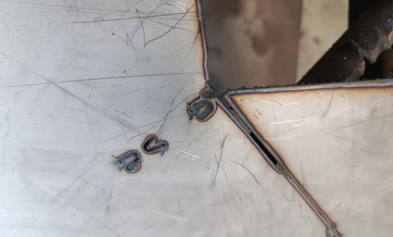
3) During the cutting process, excess material was removed due to design issues. To solve this problem, I modified the design and adjusted the dimensions before repeating the fabrication process.
Download all files