Assignment 12:- Mechanical Design and Machine Week
In the Mechanical Design and Machine Design assignment, I learned a lot about machine design, fabrication, assembly and teamwork this week. The team project taught me the importance of teamwork, communication and sharing responsibilities for the sake of a common goal. As part of the project, I contributed to the design, machine assembly,electronics integration, programming, and documentation, and helped the team with their assigned tasks. I collaborated with team members to solve problems, make design decisions, and ensure the project moved according to the schedule. We worked closely as a team during the week and we managed the resources, materials, tools and time well. We followed the Design Thinking process to understand the requirements, ideate, develop solutions and improve the design of the machine through testing and feedback. This task has also improved my project planning, resource management, documentation and time management skills. We divided the tasks efficiently and worked collectively to complete the machine within the given timeline.
Group assignment tasks
Design a machine that includes mechanism + actuation + automation + application
Build the mechanical parts and operate it manually
Document the group project
Individual assignment:
Document your individual contribution
Idea Selection Process
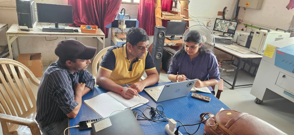
At the beginning of the week we had a brainstorm for ideas for our machine design project. After talking through a number of options, we came up with two main ideas:
• String Art Machine
• Clay Printer
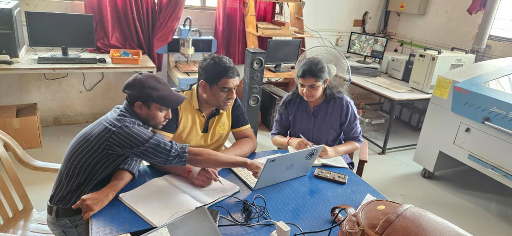
We researched both ideas, and looked at the design requirements, machine mechanisms, electronics, programming needs and overall complexity. We talked through the pros and cons of each idea and how they could be executed given the time and resources we had.
We were a small team (two students) and did not want a very complicated or ambitious project. After much consideration and planning, we settled on the idea of a Clay Printer, as it was a more feasible project to complete within the time constraints, and gave us the opportunity to demonstrate our mechanical design, electronics integration and programming skills.
Work Distribution and Planning
After we were done with the Clay Printer idea, we divided the work among the team members based on our skills and interests. We are only two students in our team so it was important to divide the tasks well so the project could be done on time.
We set up a plan and assigned responsibilities for mechanical design, electronics, programming, fabrication, assembly, testing, and documentation. My main contributions to the project were in the electronics/programming areas including hardware setup, wiring, machine control, and software configuration.
Regular discussions helped us to keep track of progress, solve problems and support each other whenever necessary. We managed our time well and completed the Clay Printer within the week we had by clearly splitting the workload and sticking to our project plan.
Ashish Shende:- My main responsibilities included Sketch, hardware development, machine assembly, clay extruder fabrication, 3D printing, laser cutting electronics integration and programming of the Clay Printer.
Arati Bhosale:- Arati was assigned the work of 3D modeling and designing the machine, laser cutting the necessary parts, helping in assembly and assisting in programming and testing.
Final machine video
Clay Printer
Resource Collection and Material Selection
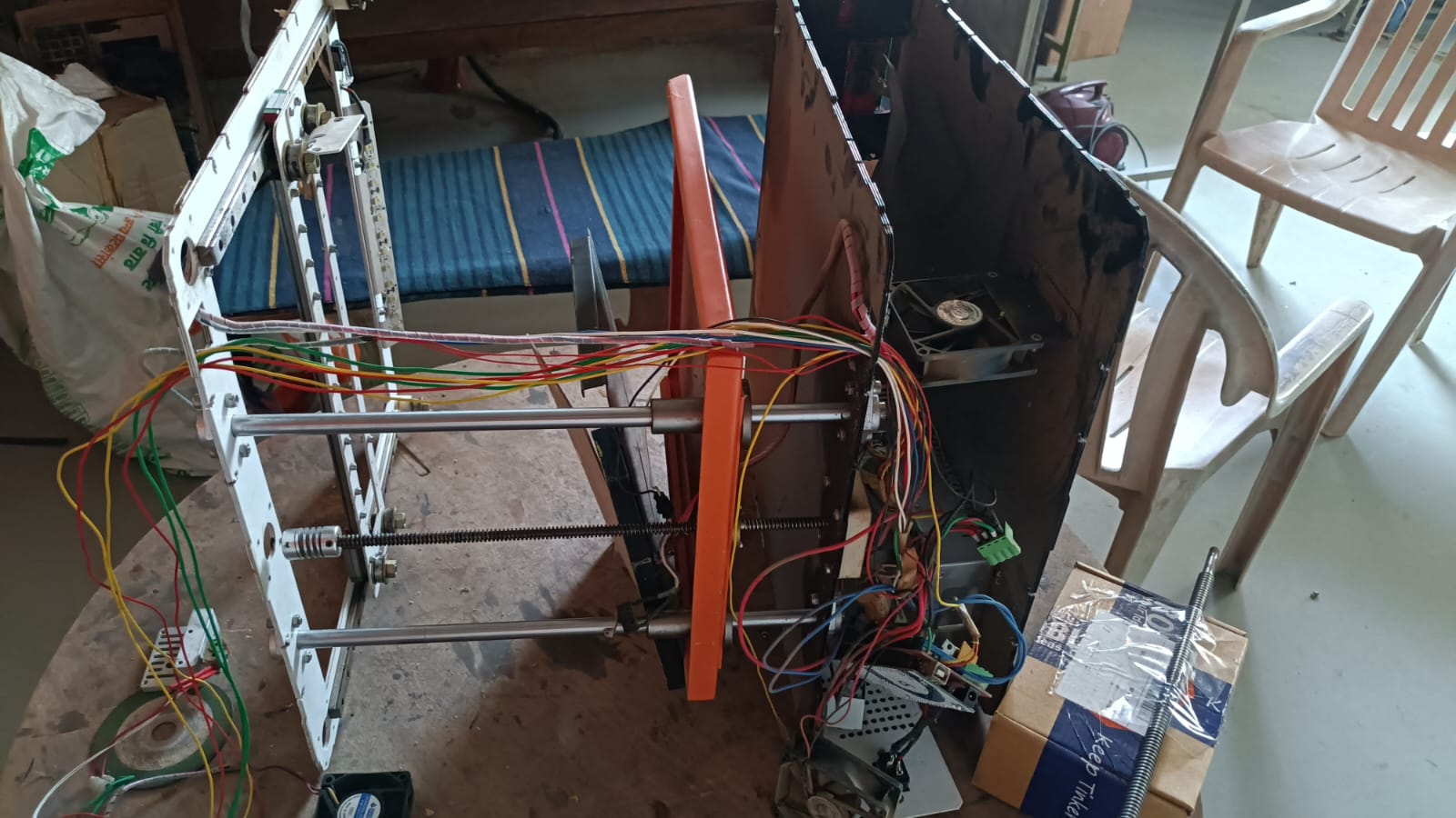
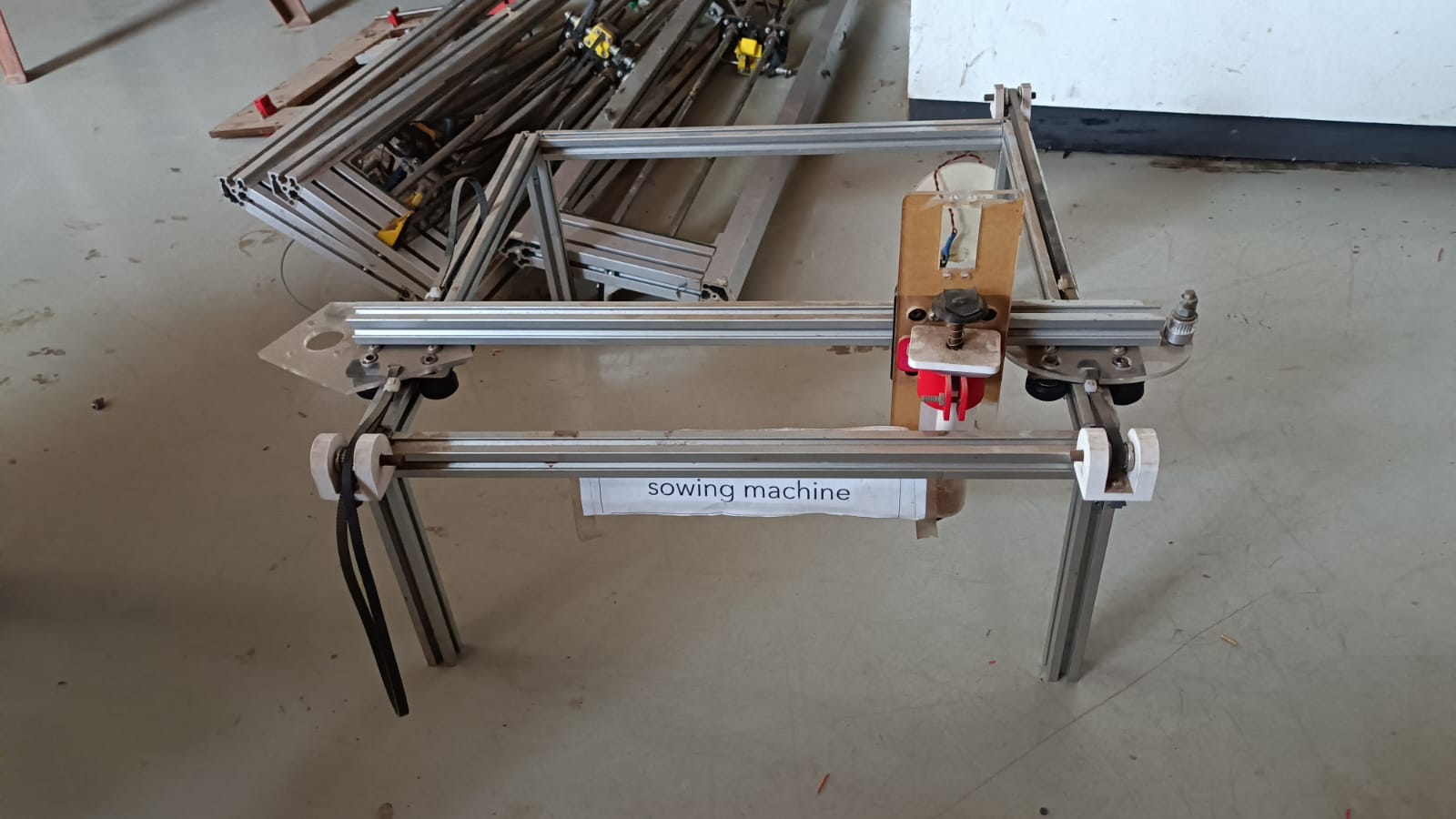
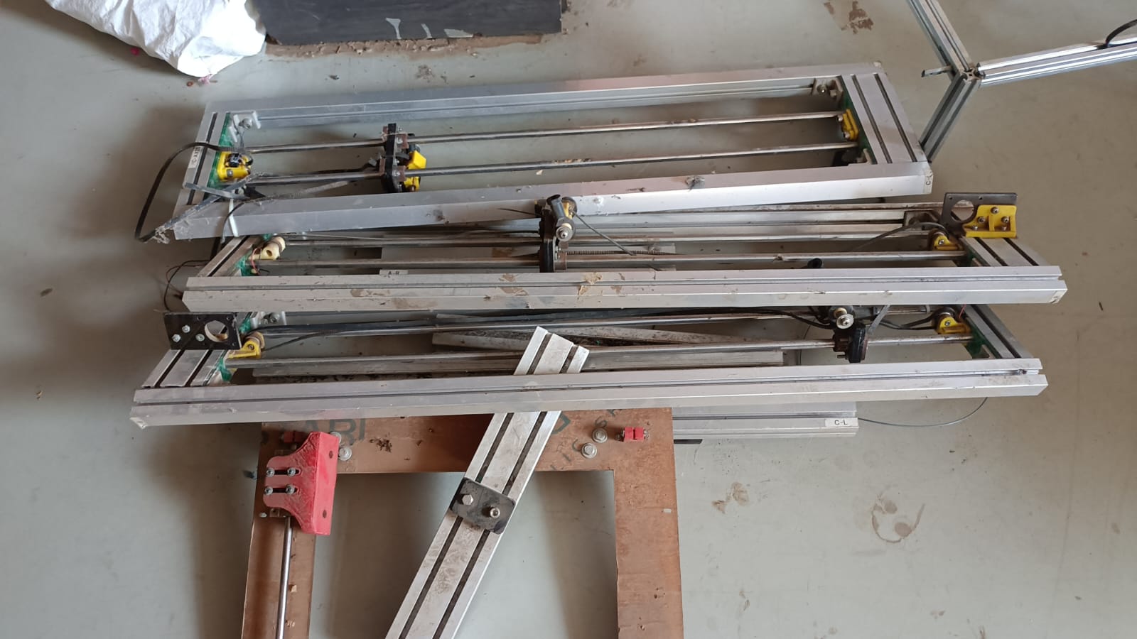
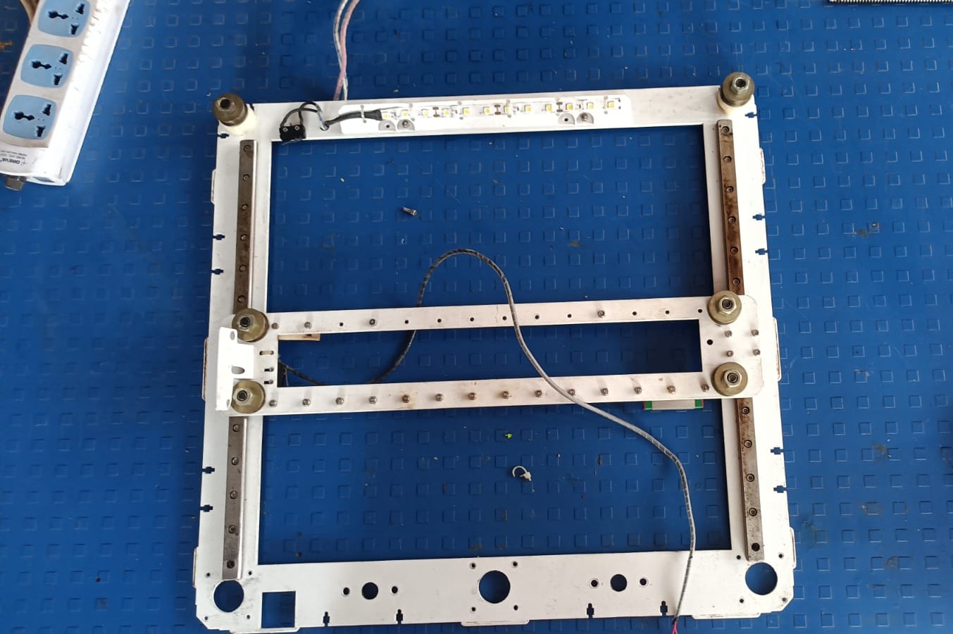
After we decided to build the Clay Printer, I first assessed the materials and resources available in our lab and looked for useful components to be recycled from discarded equipment. While I was looking through the resources available, I found an old 3D printer that was no longer being used.
We are going to reuse and recycle some parts from the old machine for our project. We disassembled the printer with great care and sorted out the reusable parts. We recovered from it linear guides, bearings, stepper motors, belts, pulleys and other useful mechanical components. This helped to reduce costs and make an efficient use of the available resources.
Sketch
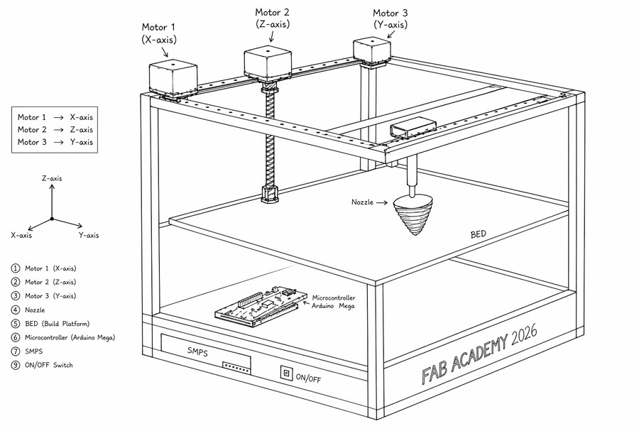
After evaluating the available resources and reusable machine parts, I created a basic sketch of the Clay Printer based on the materials and components that were accessible in our lab.
So I gave this sketch to ChatGPT and it generated a visual of my idea. The generated image helped us to visualize the machine design and to refine our ideas before starting the detailed design process.
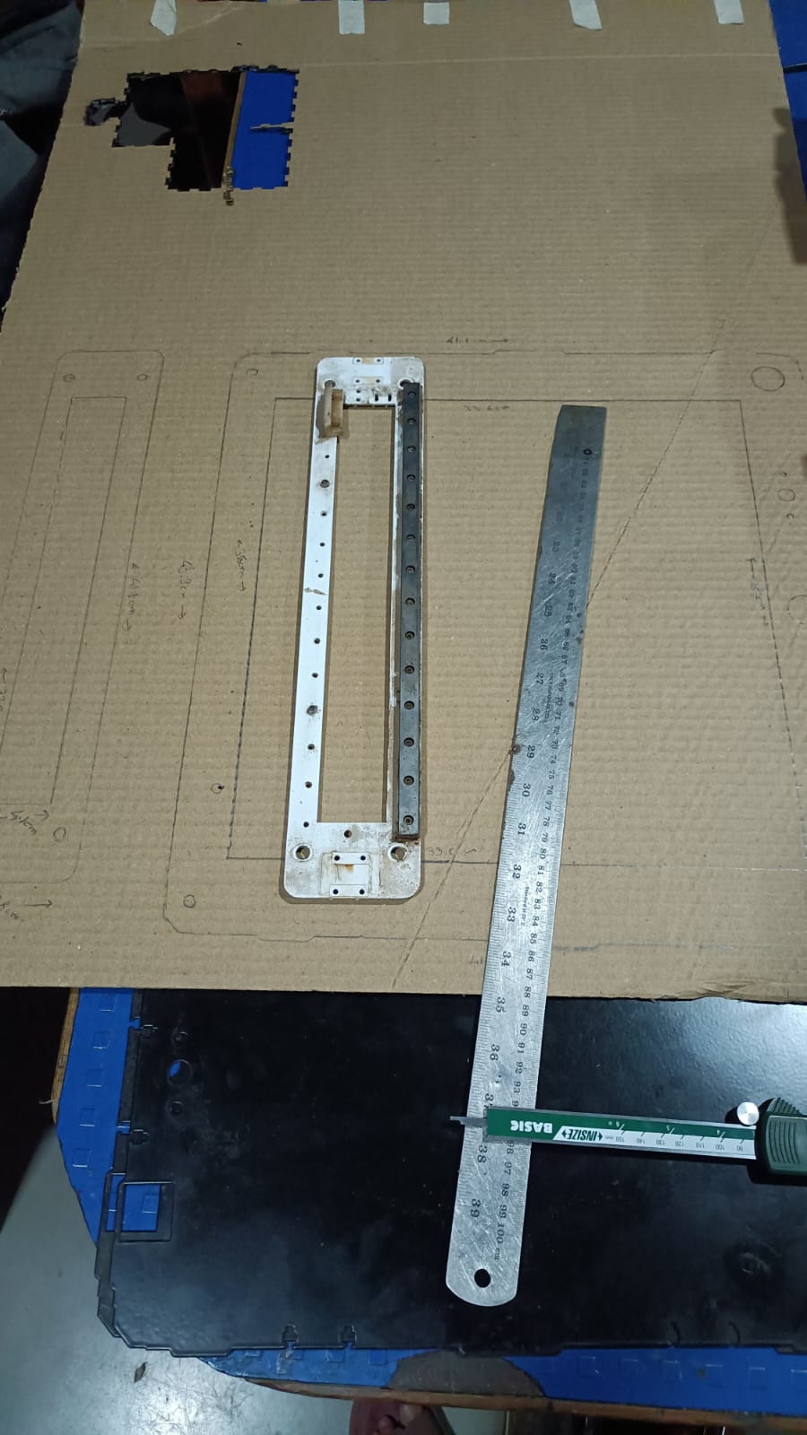
Based on the available parts and machine components, I measured the dimensions of each part and came up with the initial design idea.
Mechanism selection
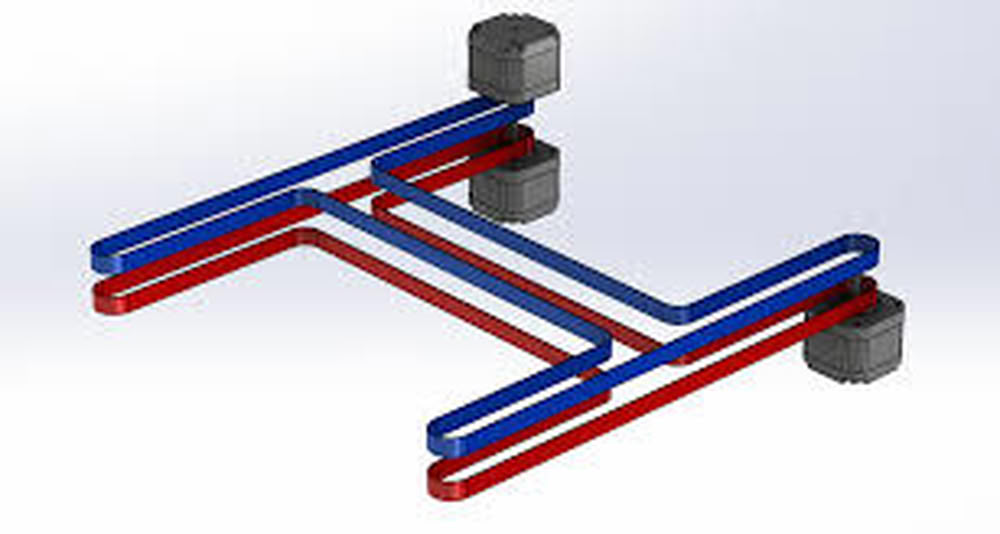
For the Clay Printer we decided to use an H-Bot mechanism for the X-Y motion system. The H-Bot design uses belts, pulleys and stepper motors to achieve precise movement while keeping the machine structure simple and lightweight. This was the correct mechanism for our project as it could be assembled with the components salvaged from the old 3D printer.
3D modling
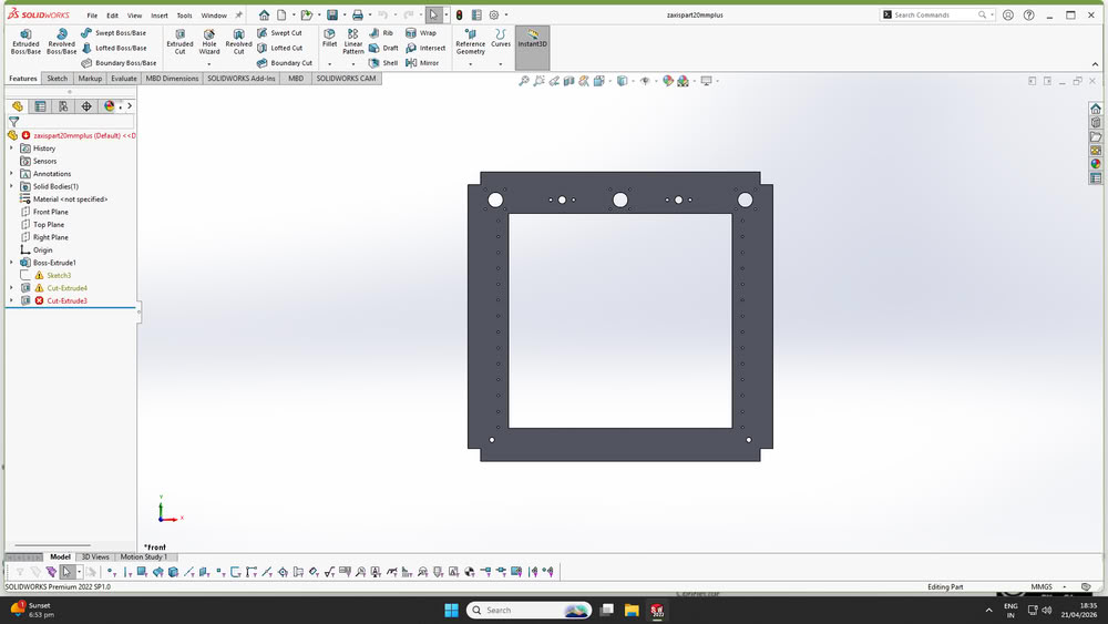
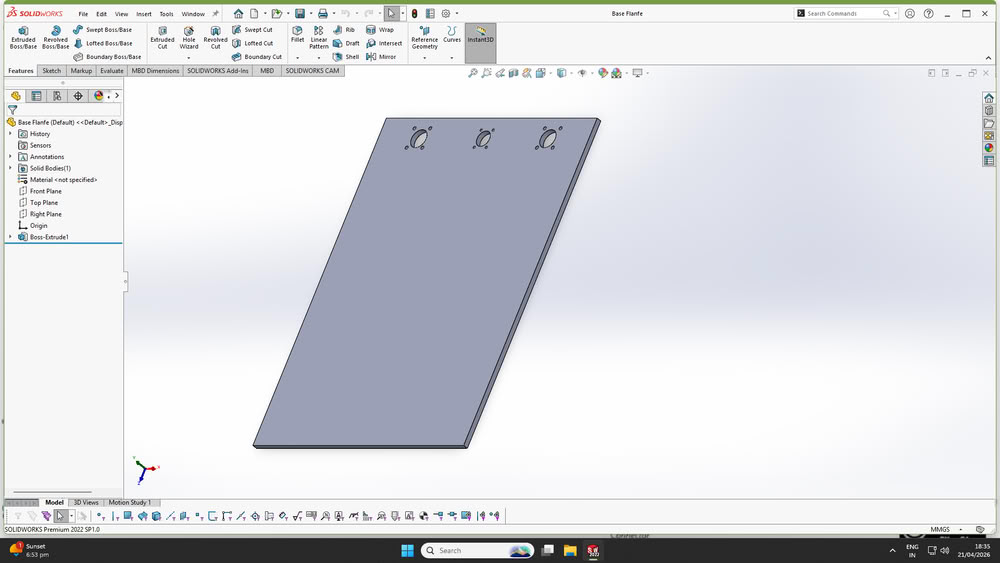
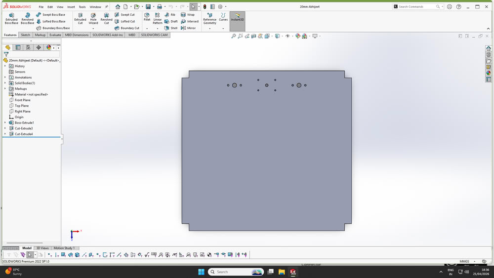
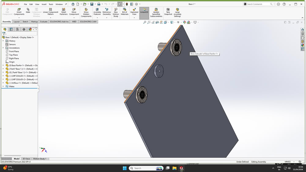
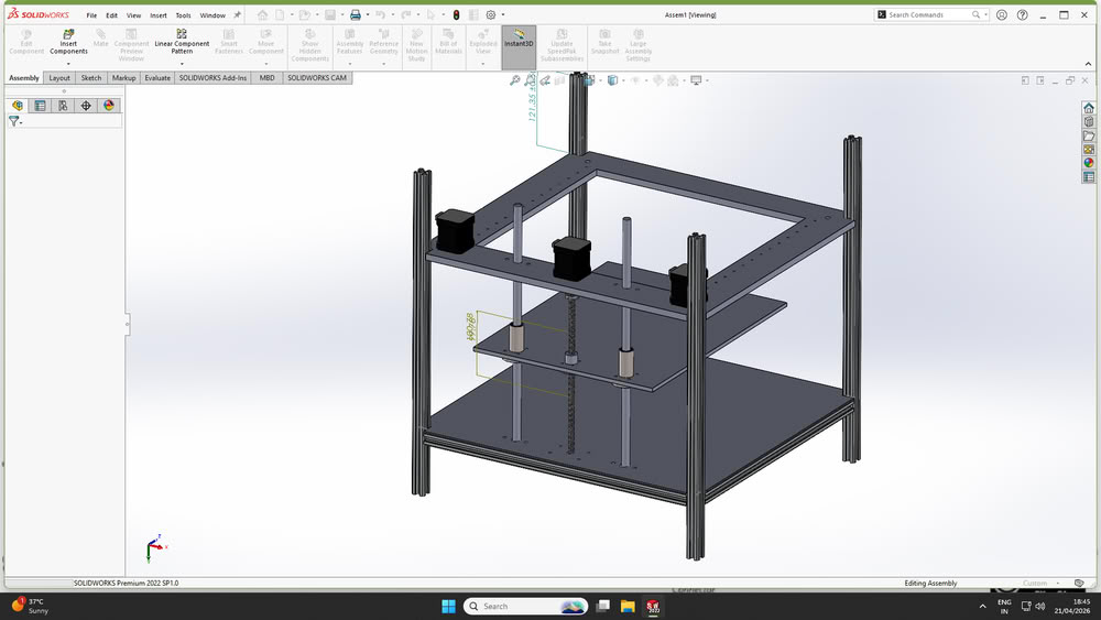
Arati worked on developing the 3d models as per these dimensions and design requirements in SolidWorks and helped refine the overall design.
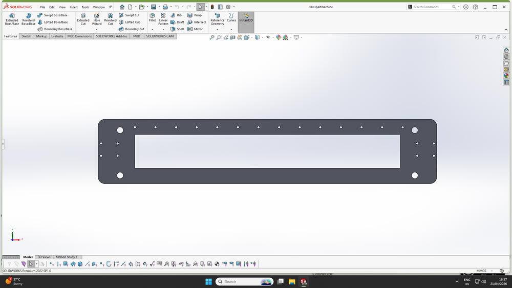
3D Assembly
cardboard prototype
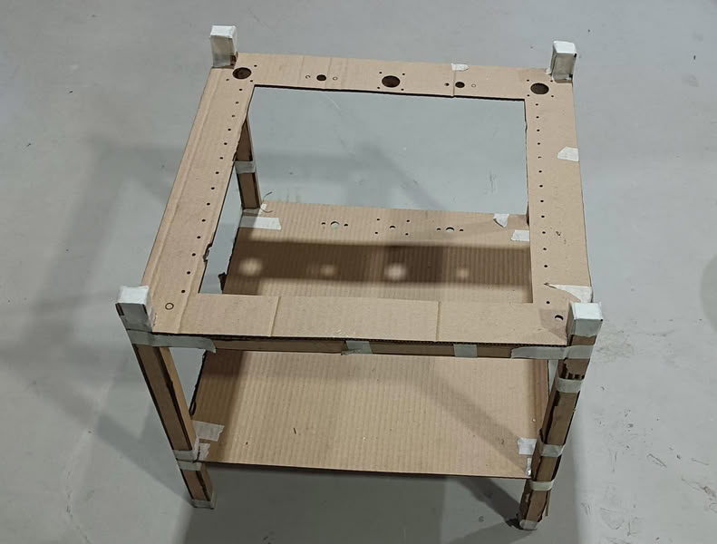
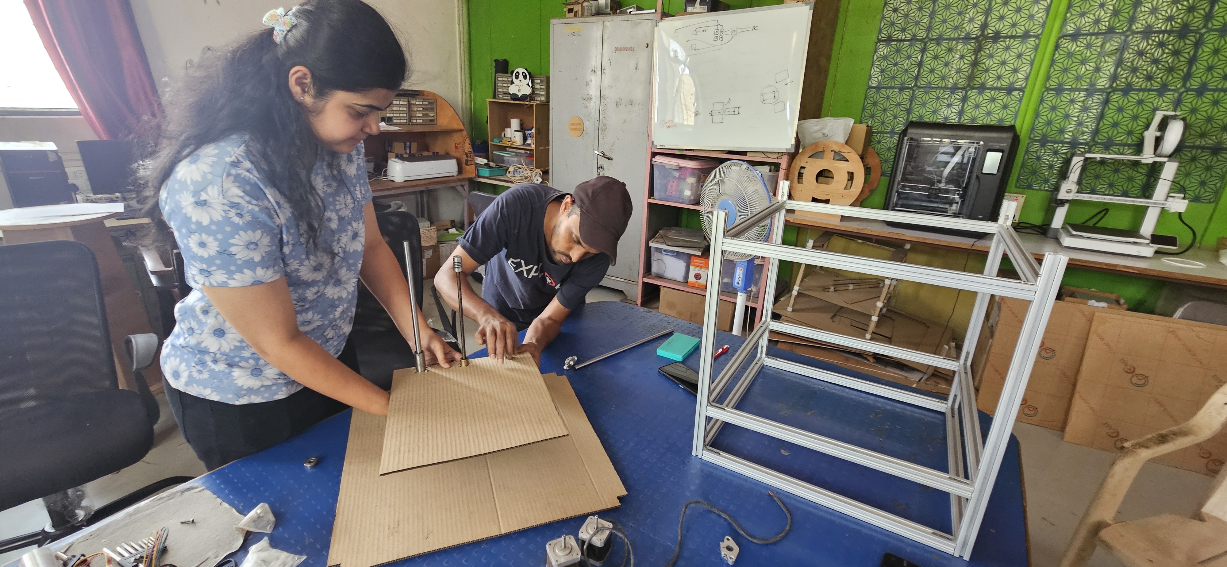
Then I started to build a prototype of the Clay Printer with cardboard. The prototype was constructed to the exact dimensions of the design to check the machine structure, placement of components and functionality before fabrication.
All the cardboard parts were cut to the design dimensions with the laser cutting machine. This allowed us to quickly put together the prototype and check the fit, alignment and general structure of the Clay Printer.
Structural Frame
The structural frame of the Clay Printer was constructed using 20×20 mm aluminum extrusion profiles. The frame gives strength, stability and correct alignment of the machine parts. The aluminum profiles were joined together by T-nuts, M4 bolts and 90-degree angle brackets to create a rigid and sturdy structure. The frame was designed based on the dimensions of the 3D model and supports the H-Bot motion mechanism, extruder system and other machine components.
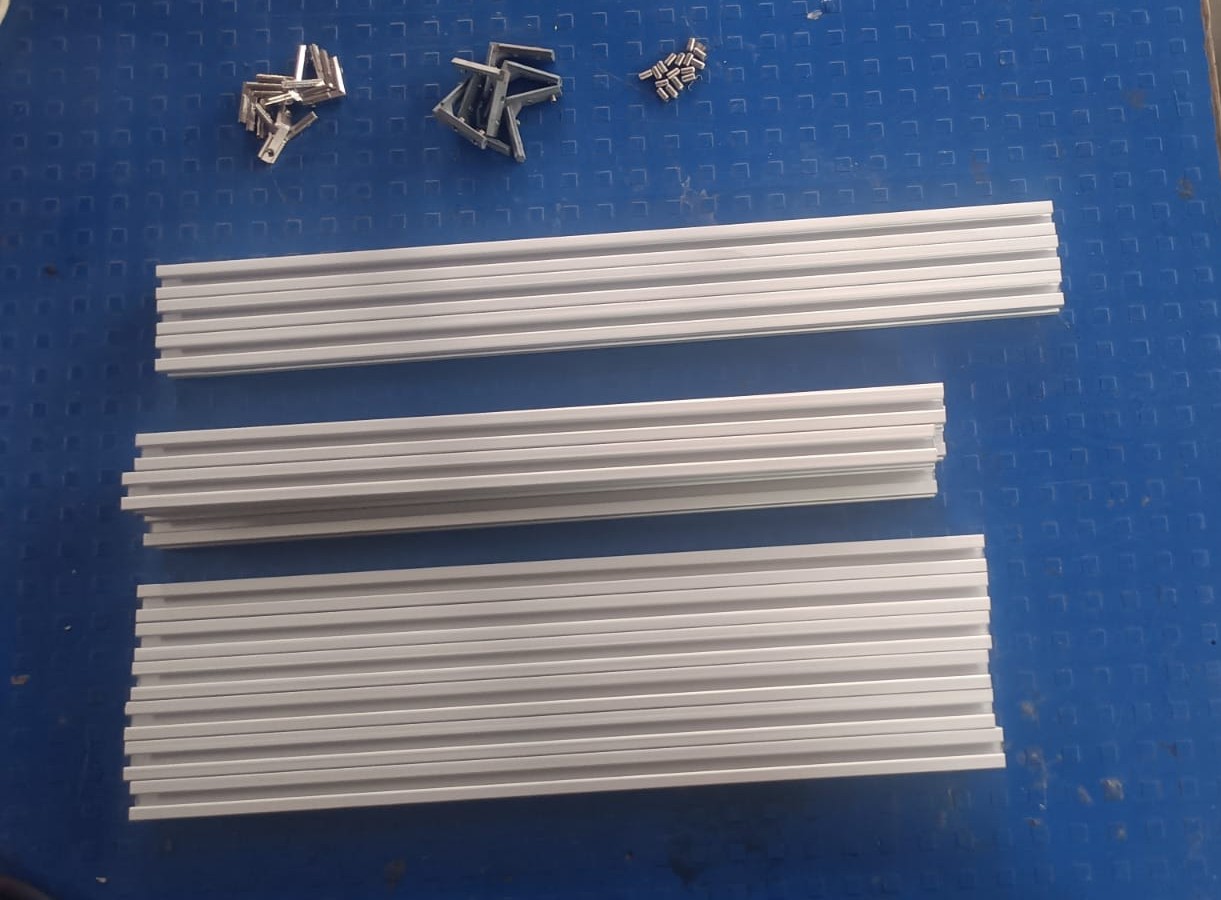
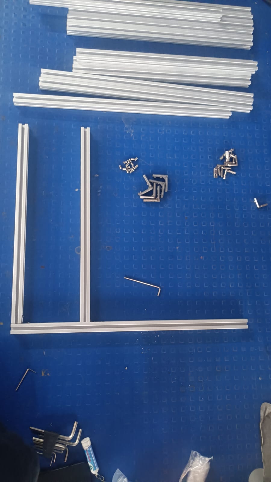
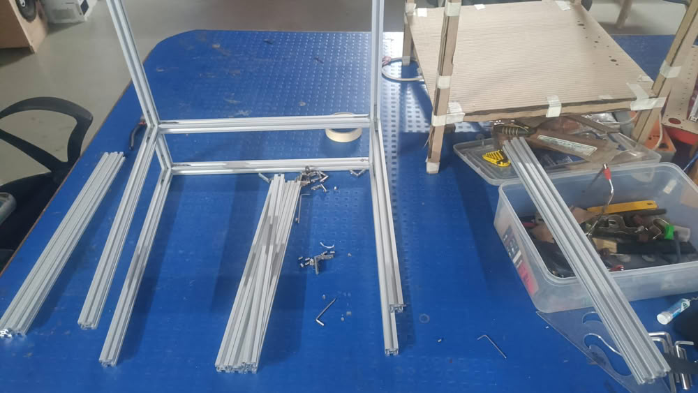
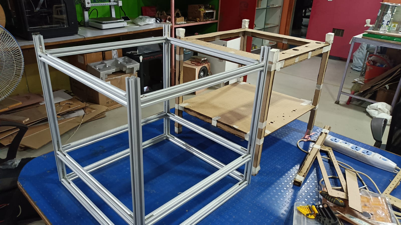
When the frame was finished we tested it with the cardboard prototype parts. This enabled us to verify the alignment of the structure, the movement of the actuators and the position of other parts of the machine. The testing process allowed us to find and correct all issues before installing the final parts and moving to the full machine assembly.
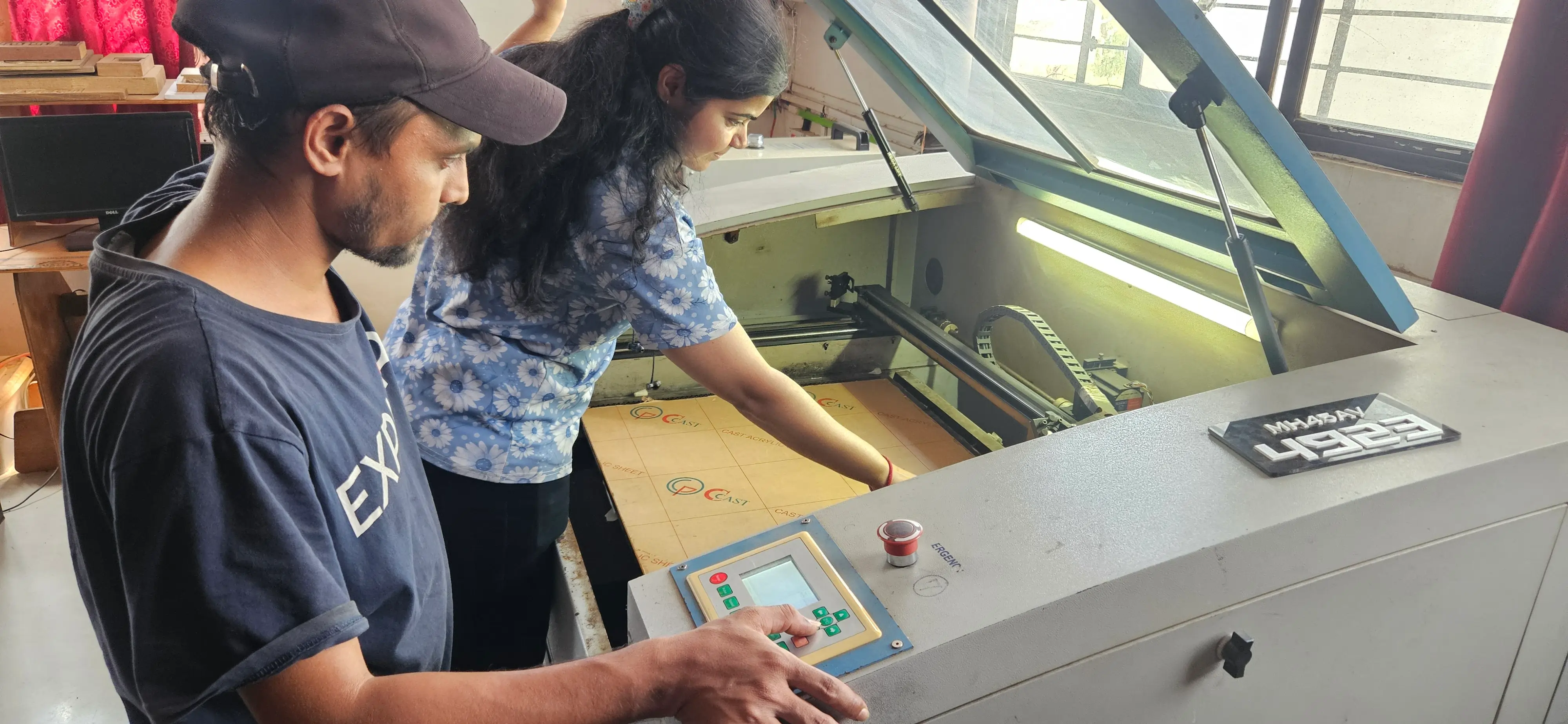
We then confirm frame and alignment and cut the final machine parts from 6 mm acrylic sheets. The acrylic parts were cut to the design sizes on the laser cutting machine and then assembled on the frame. These parts gave the Clay Printer a solid, accurate and light structure.
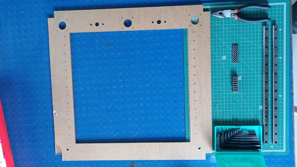
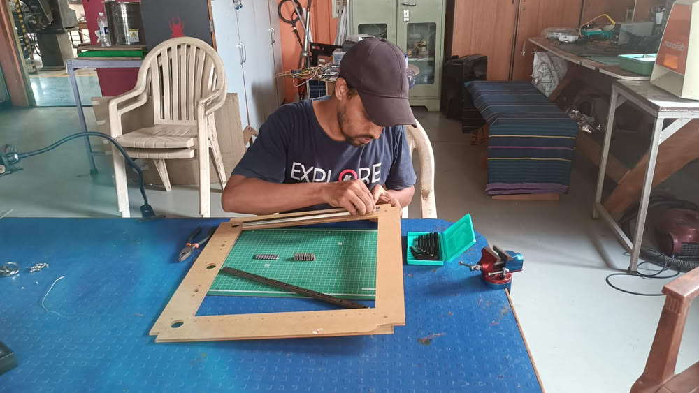
After cutting the acrylic parts on the laser cutting machine, we mounted the linear guides onto the main acrylic structure. For fastening and securing the components, we used M3 bolts, M3 nuts, and nylon lock nuts (Nyloc nuts). This ensured that the linear guides were firmly attached and properly aligned for smooth and accurate motion.
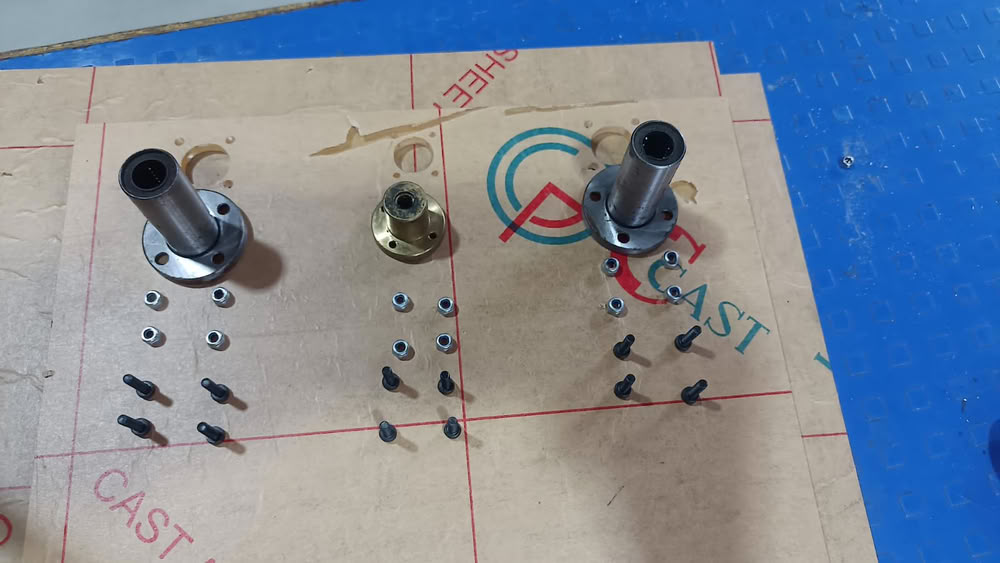
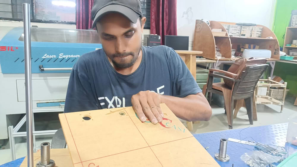
After the acrylic structure was assembled we added the linear bearings, motor mounts, shaft couplings, Z-axis guide rods, and lead screw assembly. These components were aligned and secured with precision to ensure smooth and accurate Z-axis movement during the clay-printing process.
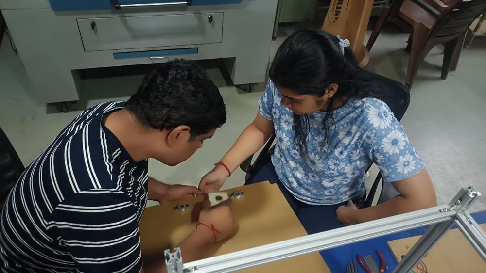
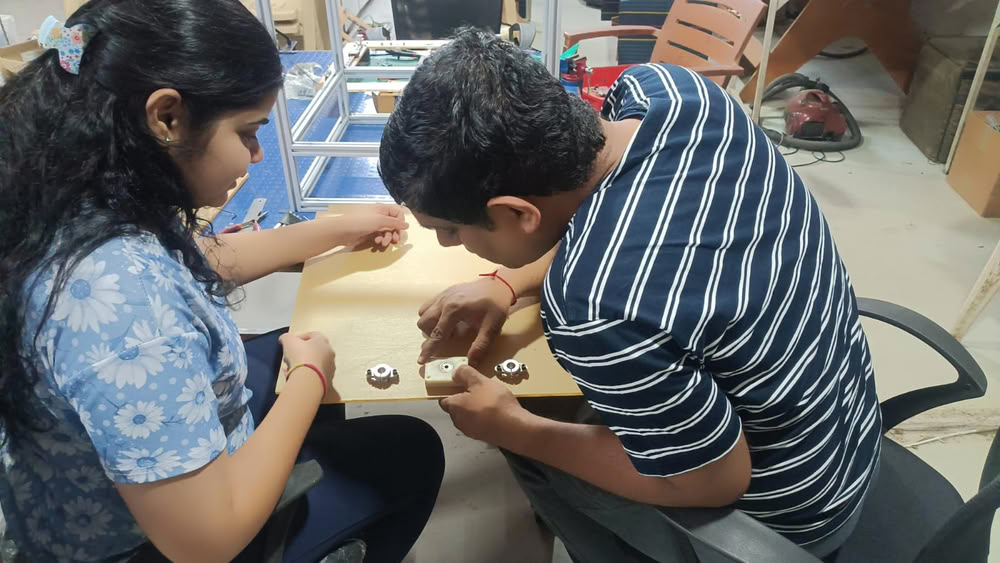
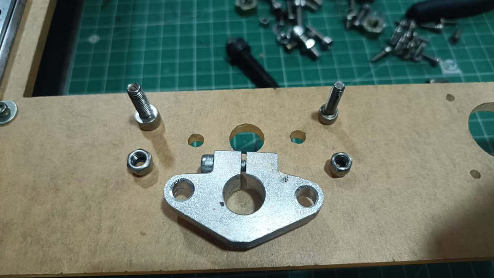
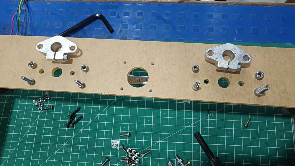
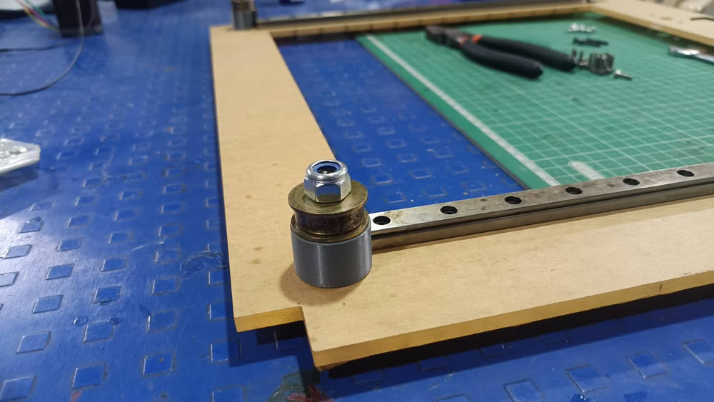
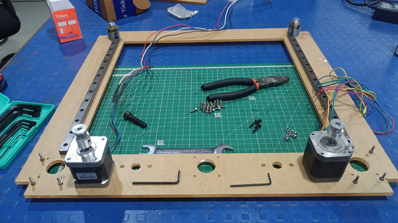
The motor mounts were glued to the top and bottom acrylic plates prior to completing the Z-axis assembly. Next, the Z-axis mechanism which is comprised of the lead screw, guide rods and motor assembly was attached to the main frame of the Clay Printer. It was held straight so it moved up and down smoothly and accurately.
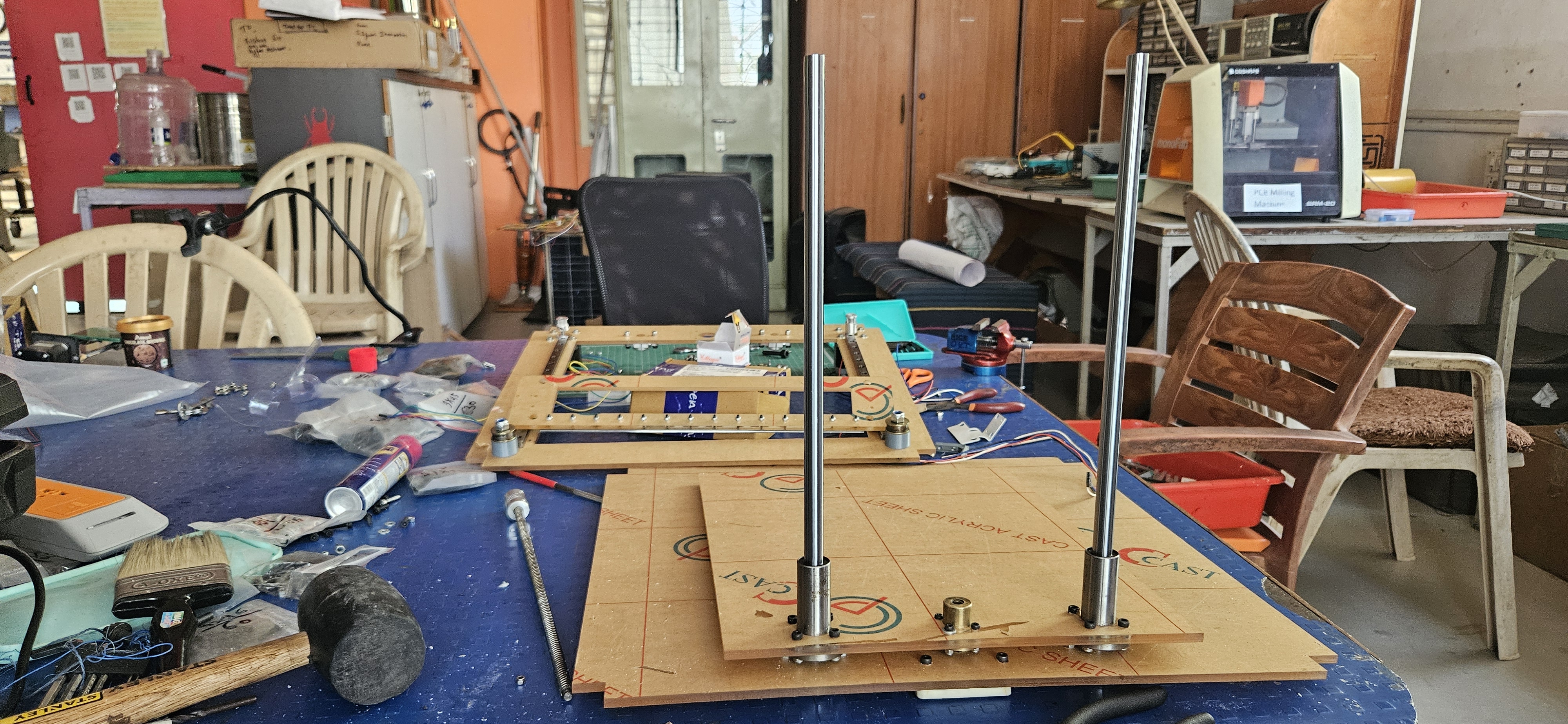 Actuation:-
After the Z-axis assembly was complete, we then performed some initial actuator testing. We tested the Z-axis movement to ensure that the lead screw, guide rods, bearings and motor all moved smoothly. This testing helped us to check the alignment, stability and overall functionality of the Z-axis mechanism before progressing to the next stage of assembly.
Actuation:-
After the Z-axis assembly was complete, we then performed some initial actuator testing. We tested the Z-axis movement to ensure that the lead screw, guide rods, bearings and motor all moved smoothly. This testing helped us to check the alignment, stability and overall functionality of the Z-axis mechanism before progressing to the next stage of assembly.
After assembling, the structure of the Clay Printer machine was prepared. Frame, motion system, Z-axis assembly and mechanical parts integration was successfully accomplished.
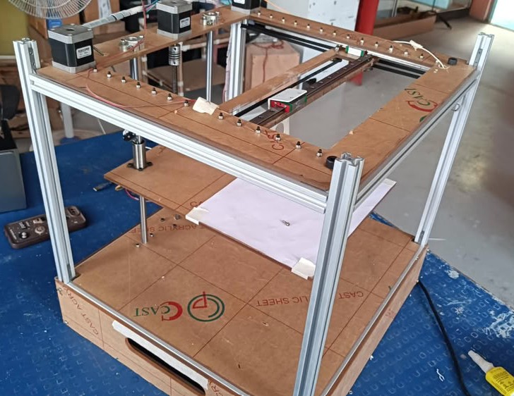 Clay Extruder Development
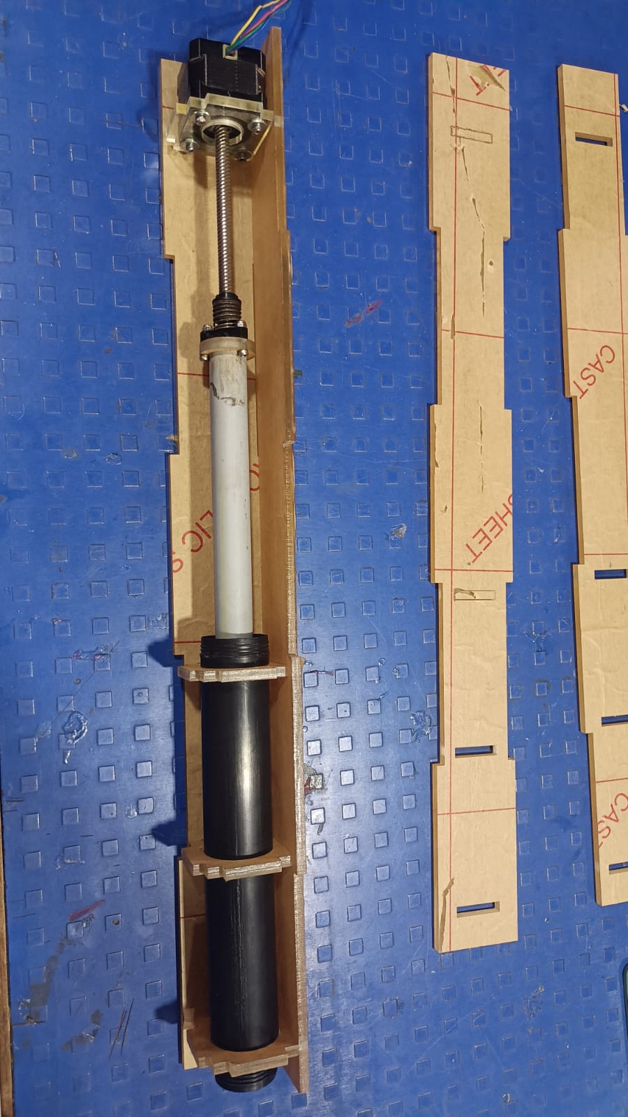
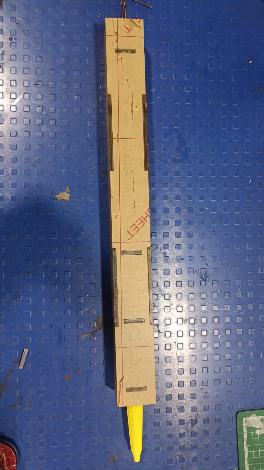
I made a bunch of custom parts for the extrusion mechanism and laser cut those to make the clay extruder.
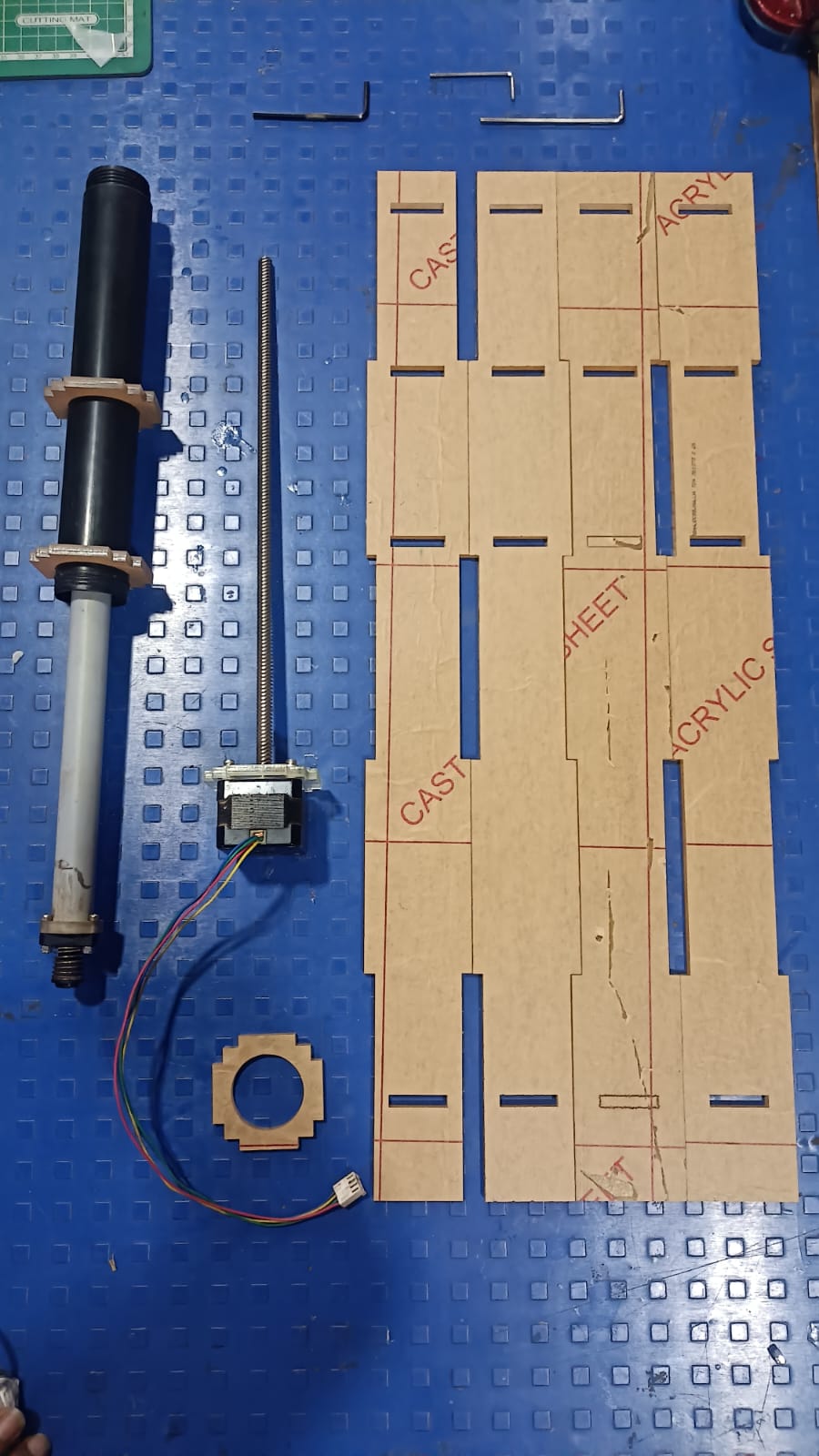
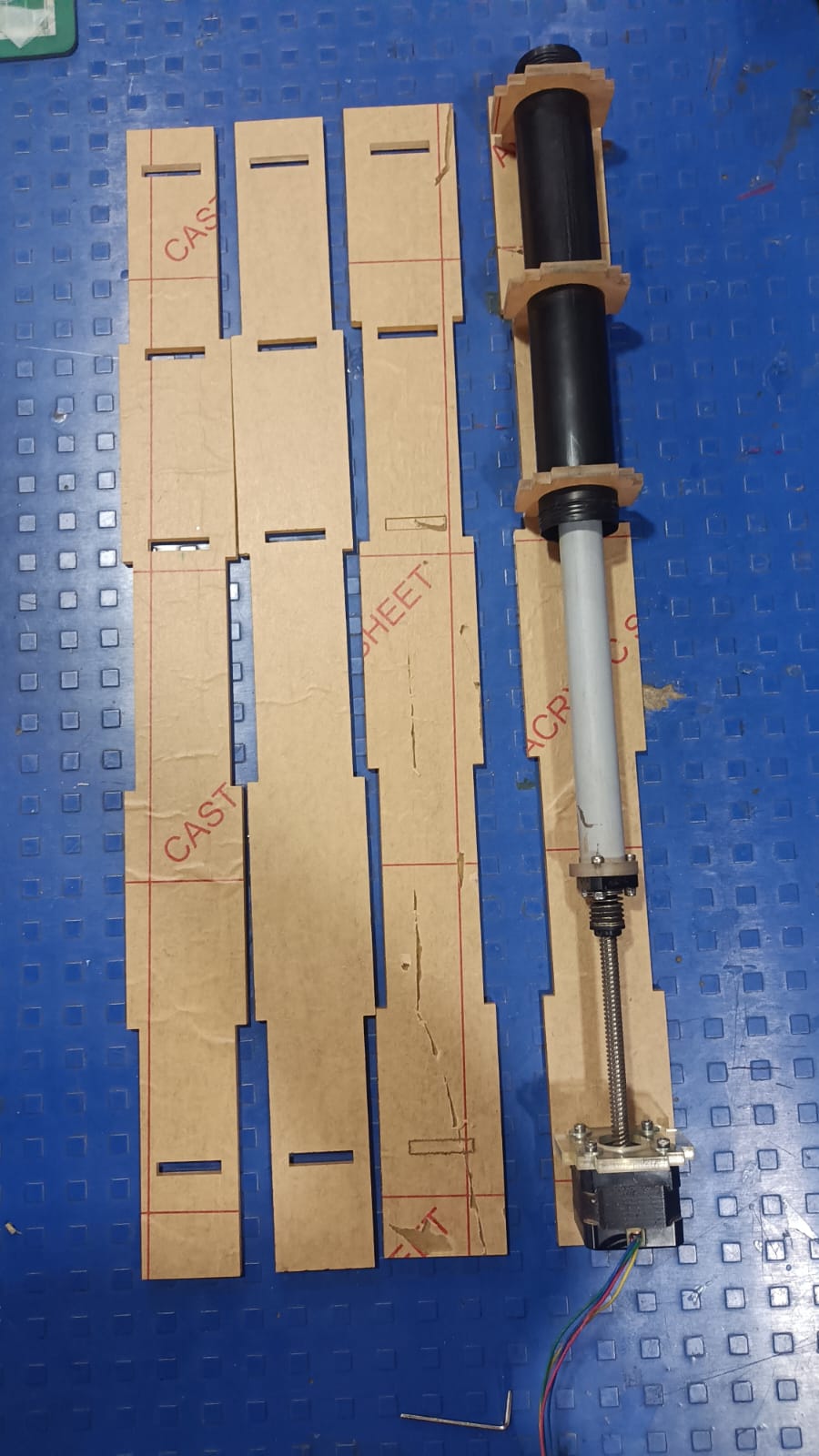
A lead screw and a stepper motor were connected to the upper part of the extruder. My first thought was that the rotating lead screw would translate the rotational motion of the motor into linear motion, so that the plunger could push the clay downwards and force it through the nozzle in a controlled way..
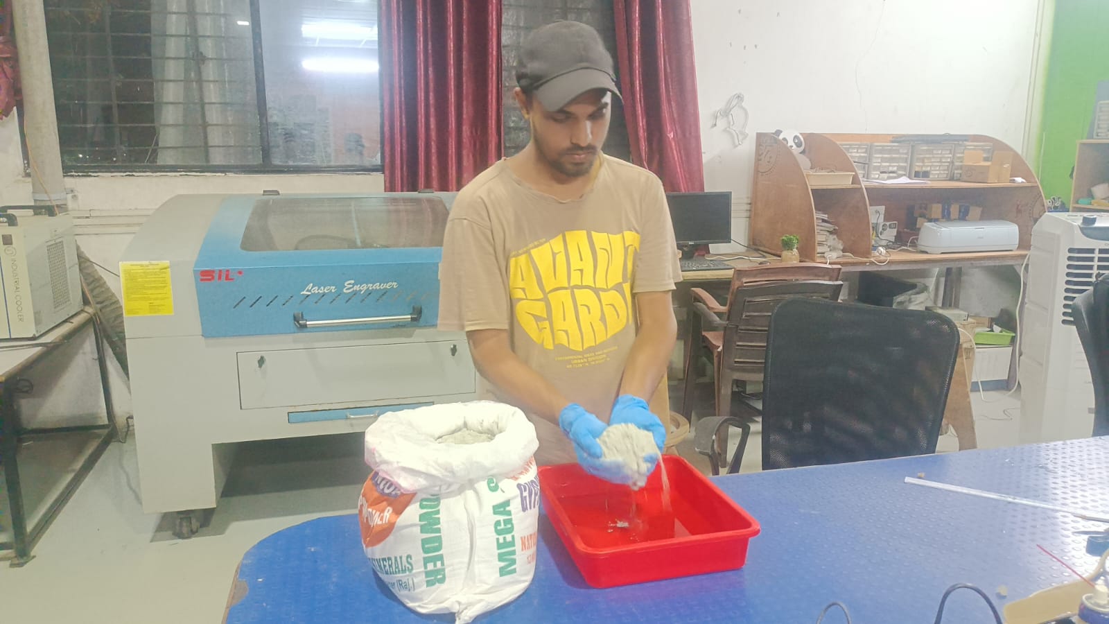
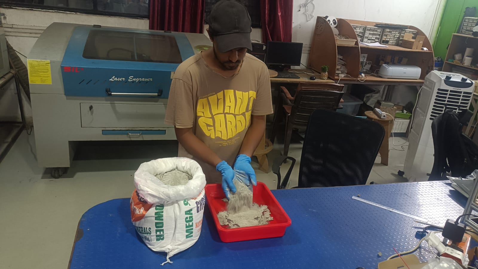
 I prepared a mix of clay before trying the extruder. The clay material that I used is called Shadu Mati and I mixed it with water till it was a smooth and consistent dough like paste that could be extruded. The mixture was carefully prepared to achieve the right viscosity and flow characteristics for the clay printing process.
Having made the clay mix, I tried out the extruder system. At first the extrusion mechanism worked and the stepper motor was able to push the clay inside the syringe.
But when I ran a 10 mm pipe from the extruder to the nozzle to get the clay to the print bed the system did not work as expected.
In the tests, the clay got stuck in the pipe and did not reach the outlet of the nozzle. Thus, the clay was not extruded on the print bed. The difficulty was caused by the resistance of the pipe and the consistency of the clay, which did not allow for a smooth flow along the extrusion path. The extrusion system and clay composition needed further modifications to improve the flow of the material.
Design Modification Extruder and Improvement
Having made the clay mix, I tried out the extruder system. At first the extrusion mechanism worked and the stepper motor was able to push the clay inside the syringe. But when I ran a 10 mm pipe from the extruder to the nozzle to get the clay to the print bed the system did not work as expected.
In the tests, the clay got stuck in the pipe and did not reach the outlet of the nozzle. Thus, the clay was not extruded on the print bed. The difficulty was caused by the resistance of the pipe and the consistency of the clay, which did not allow for a smooth flow along the extrusion path. The extrusion system and clay composition needed further modifications to improve the flow of the material.
We 3D-printed all the needed extruder parts with our Bambu A1 3D printer to create the new design. The printed parts were then assembled and attached directly onto the Y-axis carriage, creating a compact and integrated extrusion system for the Clay Printer.
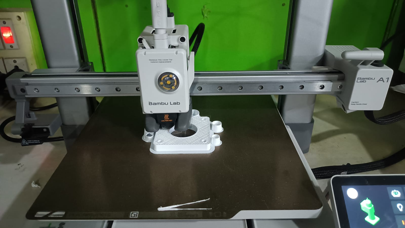
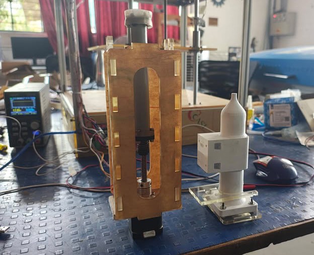 Once the parts were printed and assembled I loaded the prepared clay into the extruder via an injection method. Place the clay into the extrusion chamber carefully so that it flows in a continuous and smooth manner during the printing process. Once the extruder was filled, we started testing the clay extrusion and printing performance.
I filled the extruder with clay and sealed it tight with the top cover assembly. This held the clay in place in the extrusion chamber and enabled the stepper motor and lead screw mechanism to exert effective pressure during the extrusion process.
Next we tested the extruder. Once we had loaded the clay and sealed the extruder, we turned on the motor and made sure the clay was flowing smoothly through the nozzle. The test verified the performance of the extrusion system.
After testing the extruder successful we continued with the final assembly. The extruder was attached to the motion system and the main structure of the Clay Printer. The entire machine was available for integrated testing and calibration after installation.
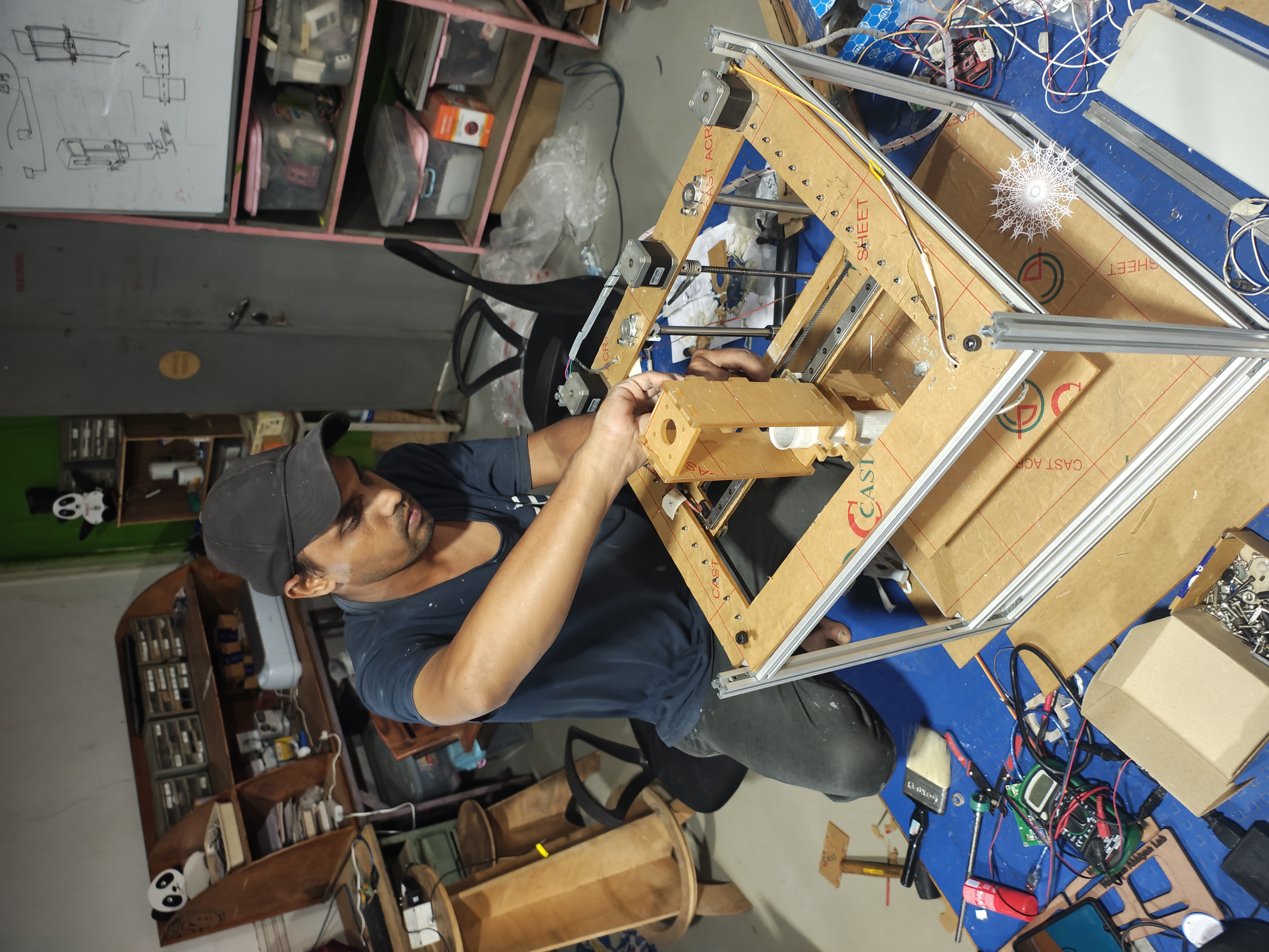
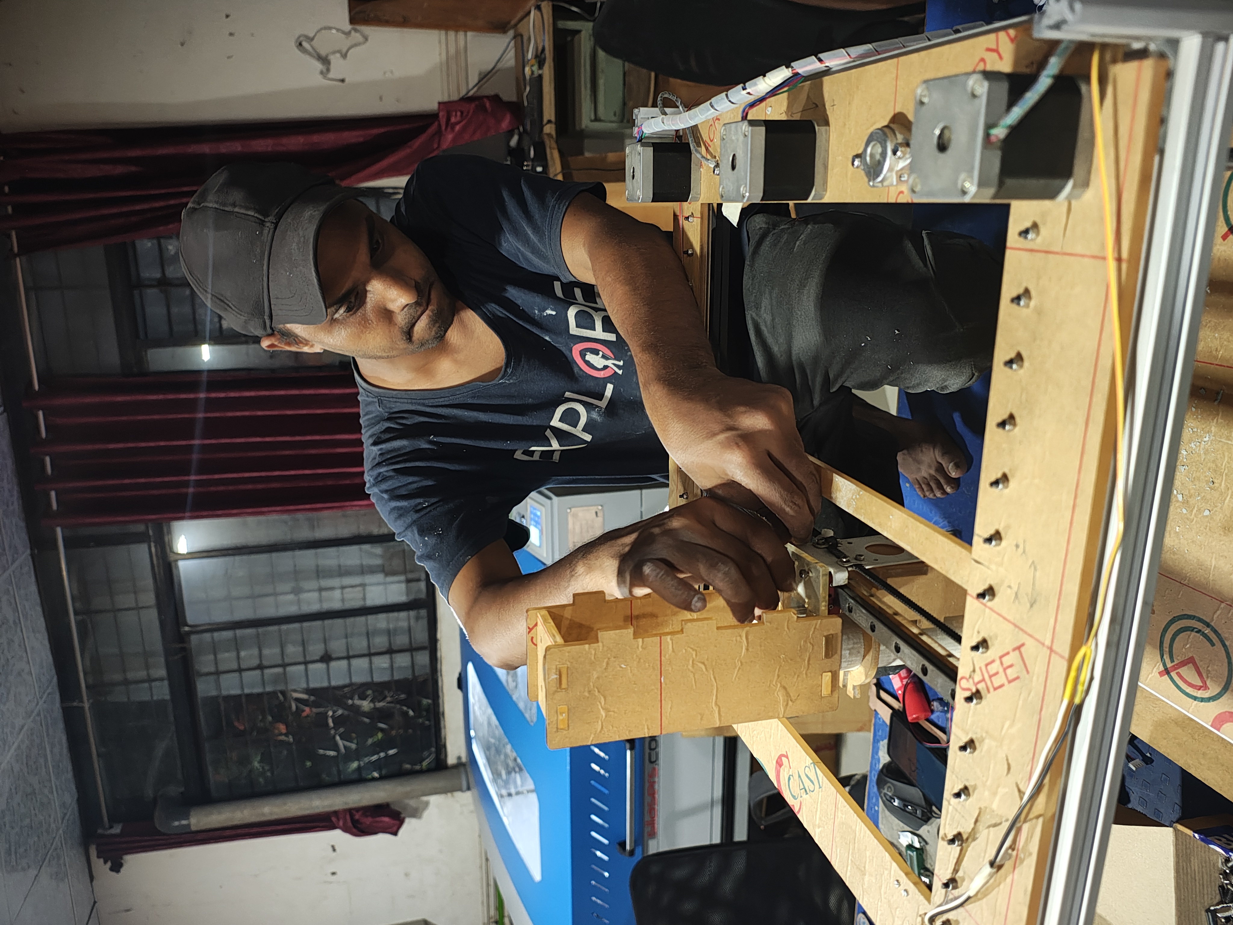
Actuation:-
We built the extruder on the machine, and then tested the actuation mechanism manually. We checked the movement of the extruder, the lead screw and the motion system to make sure that everything was moving properly and in the right way. This manual test also verified that the machine was aligned and operating properly prior to powered testing.
Electronics and Marlin Firmware:-
The clay 3D printer incorporates electronic components and control software for precise motion and controlled material extrusion. It is a microcontroller based system that interprets commands and drives the actuators.
Connection:
After establishing the connection, the brain of the system is Arduino Mega. The computer sends G-code commands to it through USB communication . It also has the firmware to process the G-code commands . It then interprets the commands and generates accurate digital control signals such as step and direction pulses required for motion control. The RAMPS shield is the connection between the Arduino and the physical components of the machine. It receives the control signals from the Arduino Mega and distributes them to different parts of the system such as stepper motor drivers, limit switches and other peripherals. It also takes care of the power distribution from the external power supply to the motors and drivers. The Arduino Mega and RAMPS shield work together as a single control unit in operation. The Arduino interprets the movement instructions, while the RAMPS shield ensures that these instructions are executed by driving the stepper motors and reading feedback from limit switches. This combination enables accurate and synchronized motion of the X, Y and Z axis of the clay printer.
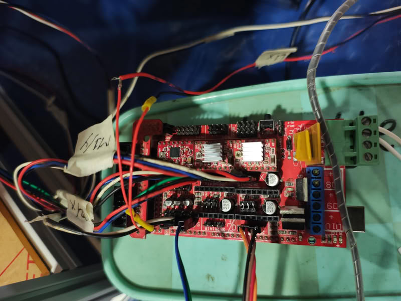
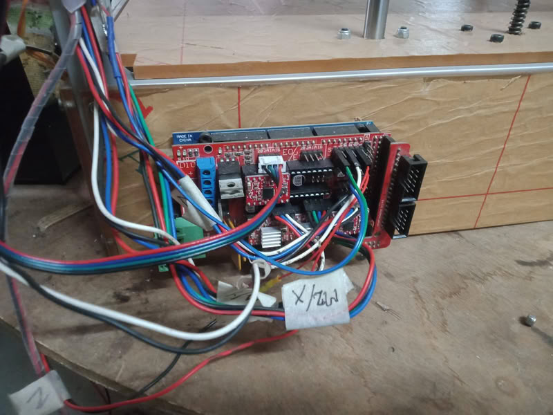 Stepper Motors (X, Y, Z Axis)
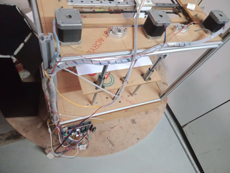
The motion of the printer was controlled by NEMA 17 stepper motors. These motors drive the print head and platform in different axes. The X and Y motors move in the X-Y plane and the Z motor moves in the Z direction. Each motor rotates in precise steps so that the print head can be positioned accurately. The motors are powered by the external power supply via the RAMPS board, ensuring stable torque and controlled movement during operation.
 Endstops (Limit Switches):-
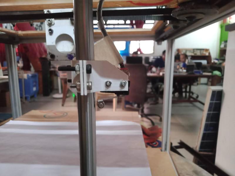
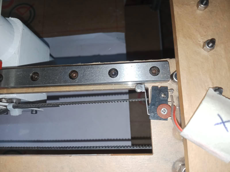
Endstop switches define the home position for each axis. These switches are safety and reference points for the machine. When an axis hits its limit , the switch tells the controller to stop moving and avoid mechanical damage . The X, Y and Z axes are homed during set-up and the printer starts from a known reference position.
 Installing Marlin Firmware and Pronterface Downloading Marlin Firmware:-
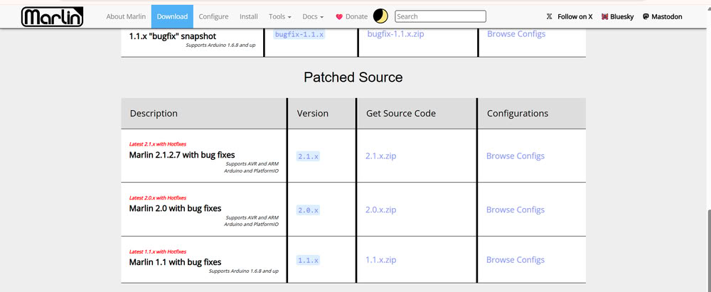
We then downloaded the firmware files of Marlin from the official Marlin GitHub repository. Marlin is an open source firmware that is commonly used on 3d printers and CNC machines. The ZIP file was downloaded and unzipped to a folder for further configuration.
Installing Marlin Firmware and Pronterface Downloading Marlin Firmware:-
We then downloaded the firmware files of Marlin from the official Marlin GitHub repository. Marlin is an open source firmware that is commonly used on 3d printers and CNC machines. The ZIP file was downloaded and unzipped to a folder for further configuration.
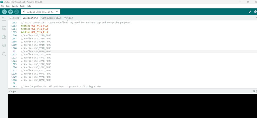
 we opened the Marlin.ino file using Arduino IDE. Once opened, multiple tabs appeared containing different firmware configuration files such as Configuration.h and Configuration_adv.h.
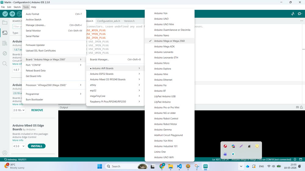
 We opened the firmware and connected the Arduino Mega board to the computer with the use of a USB cable. Then in Arduino IDE we selected the correct Arduino board by clicking on Tools → Board and selecting Arduino Mega or Mega 2560. Then we chose the right COM port from the Tools → Port section so that the IDE successfully communicates with the board.
 Then we set the firmware to our clay printer design. In the Configuration.h file we changed some important parameters like the motherboard type, baud rate, printer size, endstop setup, axis orientation and steps per millimeter. These settings were required because each machine has different dimensions and motion requirements . We configured the firmware based on our H-Bot mechanism and the structure of our machine.
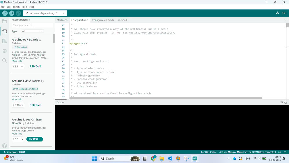
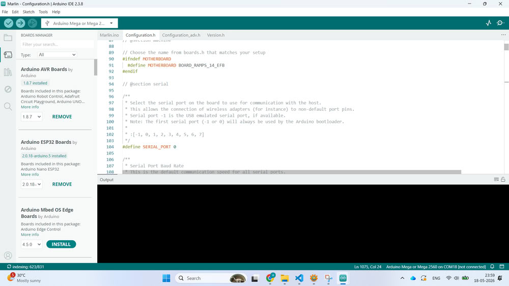
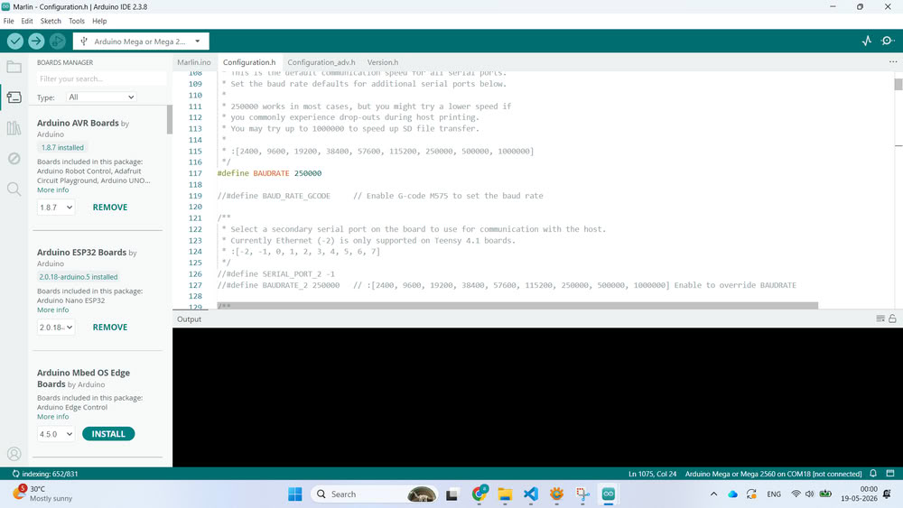 After the successful compilation , we uploaded the firmware into the Arduino Mega board by clicking the Upload button . The Arduino Mega then started running the Marlin firmware after the upload and was ready to drive the printer.
We installed Pronterface software to test the machine.
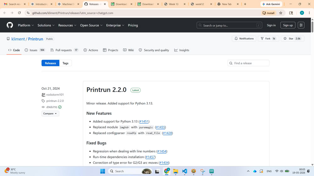 Then we downloaded and extracted the software and opened up Pronterface and selected the right COM port and baud rate. Eventually it connected successfully and the terminal window began showing communication data from the printer.
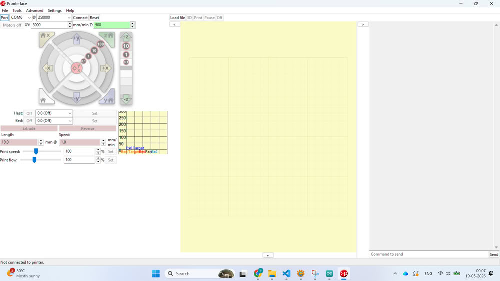
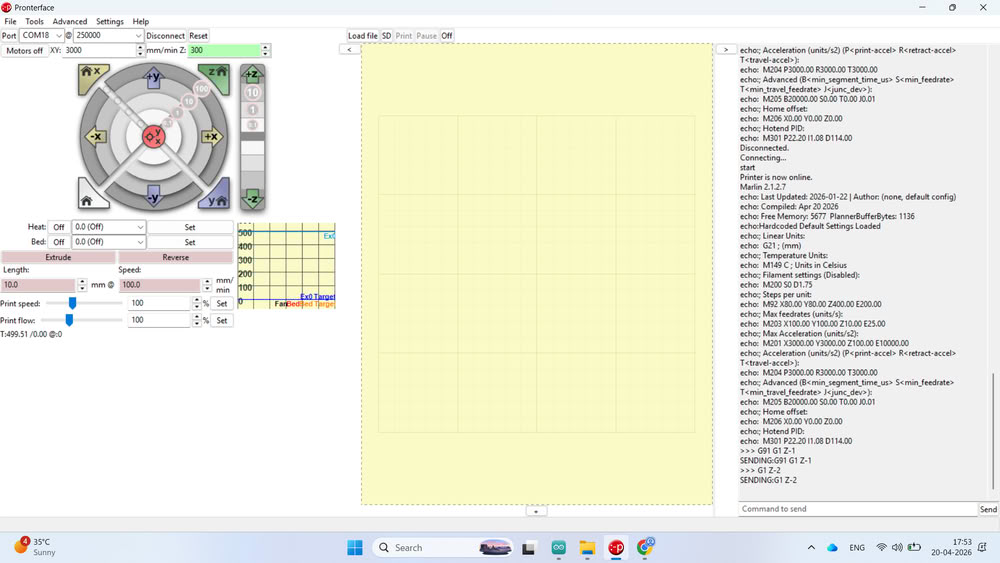 we designed a small cube model and converted the STL file into G-code using slicing software. The generated G-code file was then uploaded into Pronterface.
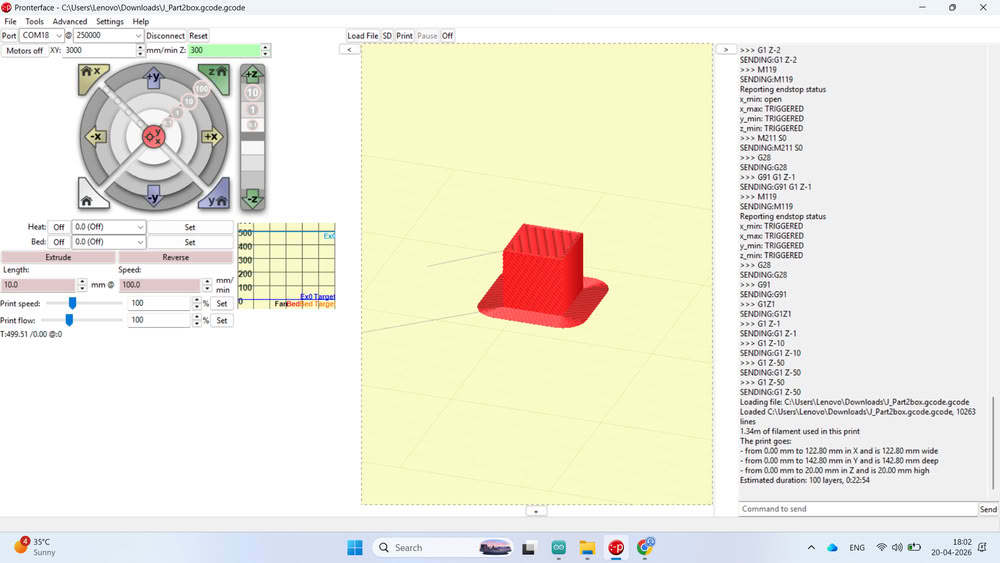
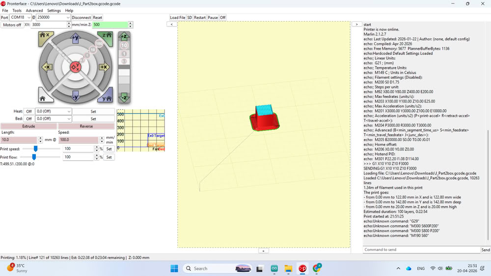
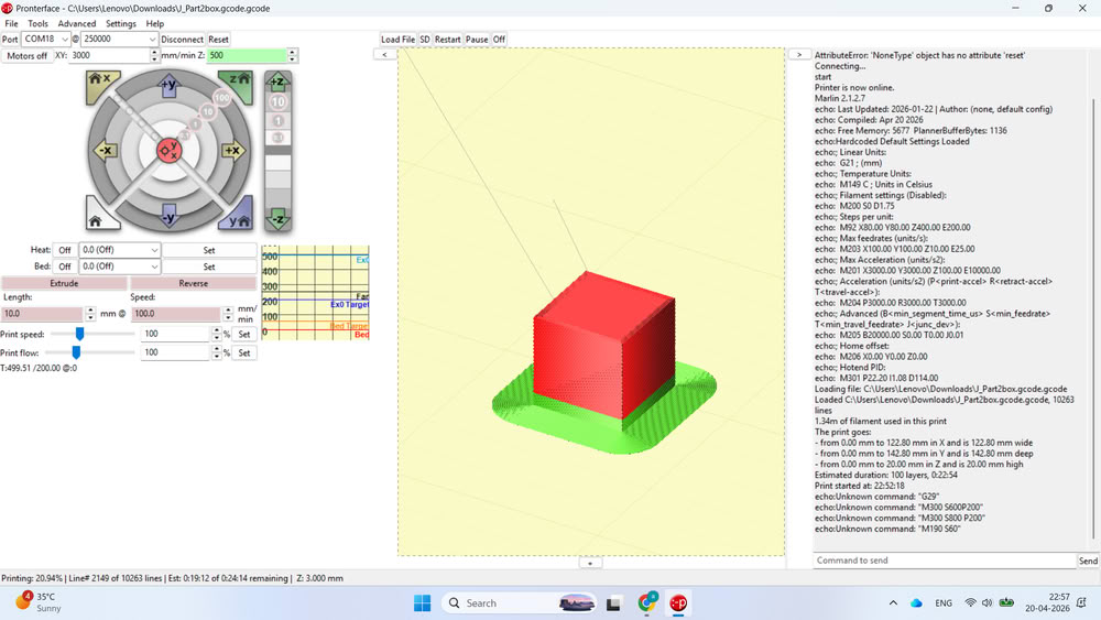 Before filling clay into the extruder, we performed a blank test run to check the movement, layer path, and overall printer operation without material. After successful testing, the clay filling process was started and the printer was prepared for actual clay printing experiments.
final video
Learning Outcomes
This week was a team-based assignment about building a machine. I learned how to work with a team and split the work evenly among the team members.
• I learned the design and build process of a clay printer, and the important components and planning for machine development.
• I learned to be resourceful, to make the best of whatever materials and tools were at hand.
• I learned the importance of managing time and completing tasks within the stipulated time frame.
• I have learned to design parts, assemble machines and put different components together to make a whole system.
• I learned to use Marlin firmware to control machines, and I learned how it is used on 2D and 3D machines like CNC machines and 3D printers.
All 2D files
Download all 2D files from here
All 3D files
Download all 3D files from here
Pronterface 3d & gcode file
Download all code files from here