Introduction
The goal of this assignment is to learn how to design electronic circuits, understand component connections, and test signals using measurement tools. Today, I explored the use of the oscilloscope to observe electrical waveforms, measure voltage, and analyze signal behavior. I connected the probe correctly, adjusted the time scale and voltage scale, and observed the waveform on the display. I also learned how to identify signal noise and understand its causes. This helped me understand real-world electronic signals and how to verify circuit performance.
Individual assignment
Task:In the individual assignment, my task was to simulate a circuit, and use an EDA tool to design an embedded microcontroller system using parts from the inventory, and check its design rules for fabrication.
Group assignment
Task:In the group assignment, our task was to use the test equipment in your lab to observe the operations of an embedded microcontroller.
Link to view group assignmentGroup Assignment
Electronic Design:-
Electronic design is the process of planning and creating an electronic circuit so that it can do a useful job. It is not just a collection of electronic components, but it is about choosing the right components like LEDs, resistors, buttons, and microcontrollers, and connecting them in the correct way so they work together properly. Just like building a toy car needs wheels, a motor, and a battery arranged correctly, electronic design needs components arranged in a smart way to make things like blinking lights, sensors, robots, and computers work. It also includes drawing the circuit diagram and making a PCB so the circuit is neat, safe, and works correctly.
What is Current?
Electric current is the flow of electricity from one place to another, like water flowing in a pipe.Electric current is the flow of electric charge through a wire or circuit. It shows how much electricity is moving. Current is measured in Ampere (A). Current flows only when there is a complete path called a circuit. Too much current can damage components, so resistors are used to control it.
Types of Current:- Direct current and Alternating current
Direct Current flows in only one direction. It is stable and commonly used in electronic devices like batteries, mobile phones, and microcontrollers such as ESP32. In DC, the positive and negative sides do not change.
Alternating Current flows in both directions, changing direction again and again very fast. It is used in homes, schools, and industries to run fans, lights, and appliances.
What is Voltage?
Voltage is the force that pushes electric current through a circuit, like pressure pushes water in a pipe. It is measured in Volt (V). A battery or power supply provides voltage. Without voltage, current cannot flow.
What is Power?
Power is the amount of electrical energy used or produced in a circuit. It tells how fast energy is being used. Power is measured in Watt (W). Power can be calculated using the formula:Power = Voltage × Current (P = V × I).
What is Resistance?
Resistance is something that slows down electricity in a wire. It works like a small gate that controls how fast electricity can move. This helps protect things like LEDs so they do not get damaged. Resistance is measured in Ohm (Ω),
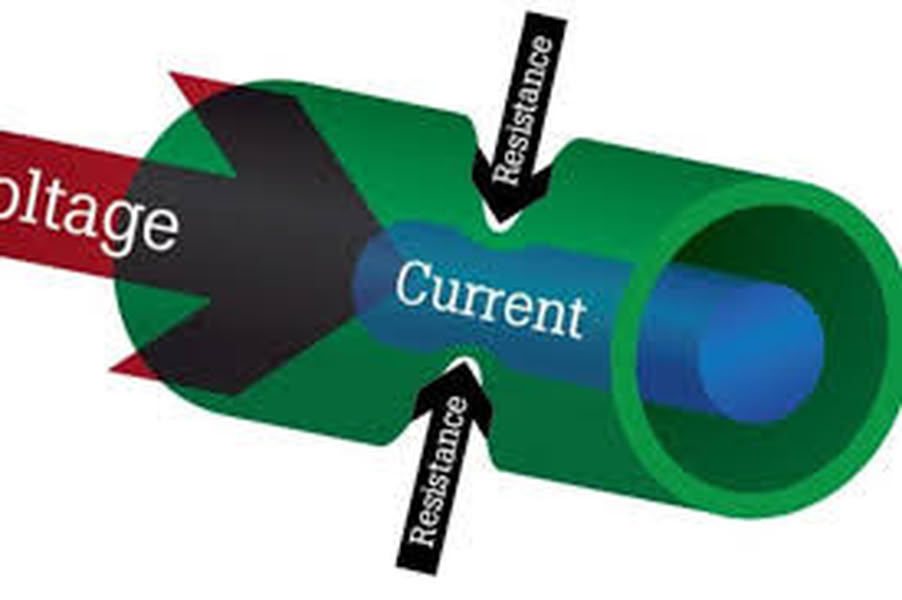
Ohm's Law:
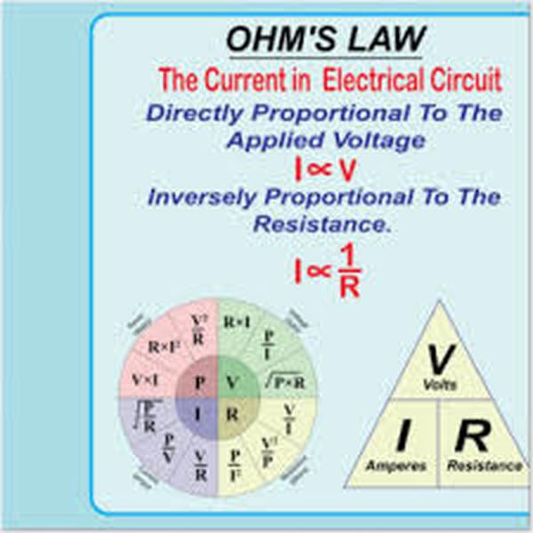
Ohm’s Law states that the current flowing in a circuit depends on the voltage and resistance. It means if voltage increases, current increases, and if resistance increases, current decreases. Ohm’s Law is written as:V = I × R, where V= Voltage, I = Current and R= Resistance.
Kirchhoffs Law:
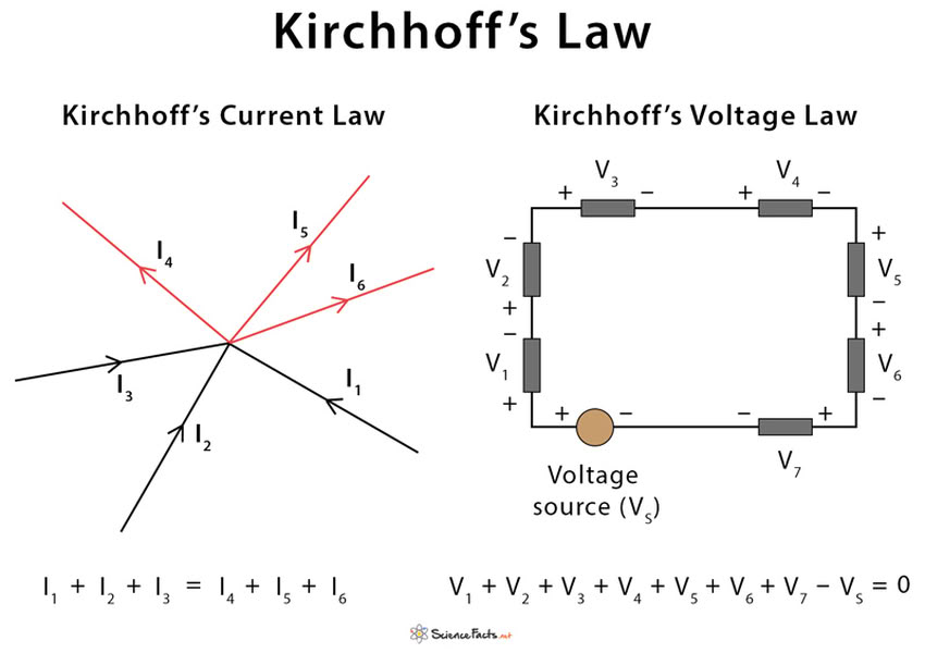
Kirchhoff’s Laws are two important laws used to understand how current and voltage behave in an electrical circuit.
Kirchhoffs Current Law
Kirchhoff’s Current Law says that electricity that comes to a point must also go out from that point. Electricity cannot disappear or be lost at that point. If electricity comes from one wire and splits into two wires, the total electricity is still the same.This law helps us understand and calculate current in electronic circuits.
Kirchhoffs Voltage Law
Kirchhoff’s Voltage Law says that the total voltage in a closed path is always equal. The voltage given by a battery is used by different components like LEDs and resistors. The total voltage used is equal to the voltage given.This law helps us understand how voltage is used in circuits and helps us design safe and correct electronic circuits.
Electronic Components:-
Electronic components are small parts used to build electronic circuits and devices. Each component has a special job to help the circuit work properly. For example, a resistor controls the flow of current, an LED gives light, a capacitor stores electrical energy, and a microcontroller controls the whole system. These components are connected using wires or on a PCB to perform useful functions. Electronic components are used in many devices like mobile phones, computers, robots, and TVs. By selecting and connecting the right components correctly, we can design circuits that perform tasks like blinking LEDs, sensing temperature, or controlling motors.
1.Resistor:-
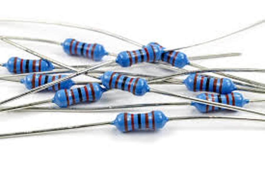
A resistor is a basic electronic component used to control and limit the flow of electric current in a circuit. It helps protect sensitive components like LEDs, microcontrollers, and sensors from getting too much current, which can damage them. Resistance is the property that opposes the flow of current, and it is measured in Ohm (Ω), named after Georg Simon Ohm. Resistors are used in almost all electronic circuits to ensure safe and proper operation. They can also be used to divide voltage, reduce signal levels, and set correct operating conditions for components. Resistors come in different values and sizes, such as 1206 SMD resistors used in PCB design. They do not store energy but only reduce or control current. Without resistors, many electronic components would burn or malfunction due to excess current.
2.Push Button
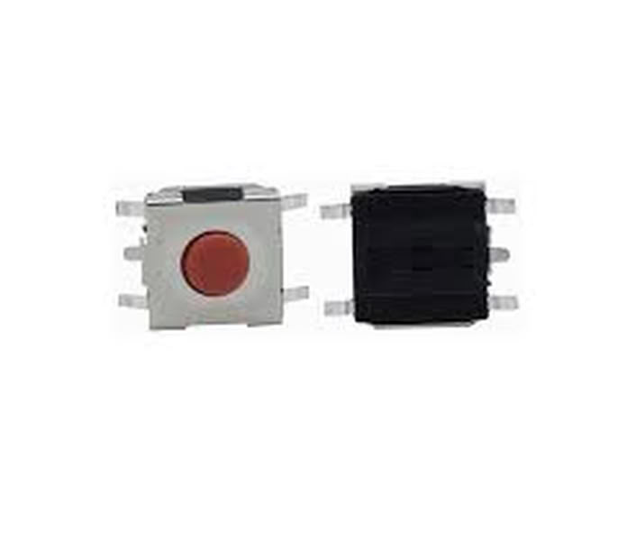
A push button tactile switch is an electronic component used to control a circuit by pressing it. When the button is pressed, it connects the circuit and allows current to flow, and when released, it disconnects the circuit and stops the current. It is called tactile because it gives a small physical feedback or click when pressed. Tactile switches are commonly used in electronic devices like calculators, keyboards, and microcontroller circuits to give input. They are small, easy to use, and commonly used in PCB design for user control.
3.Switches
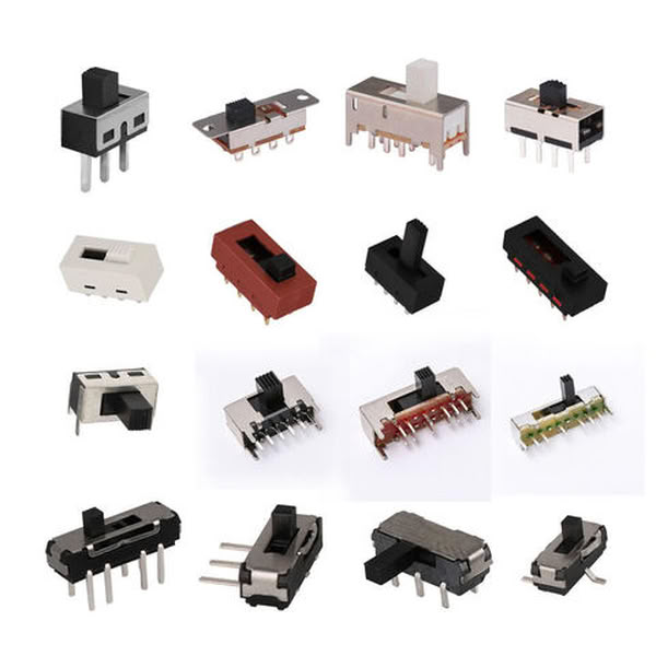
Switches are electronic components used to control the flow of electric current in a circuit by turning it ON or OFF. When a switch is ON (closed), it allows current to flow and the device works. When it is OFF (open), it stops the current and the device stops working. Switches are used in many electronic devices like lights, fans, computers, and microcontroller circuits. They help users control circuits easily and safely. Common types of switches include push button switches, toggle switches, and slide switches, and they are widely used in PCB design and electronic systems.
4.Capacitors
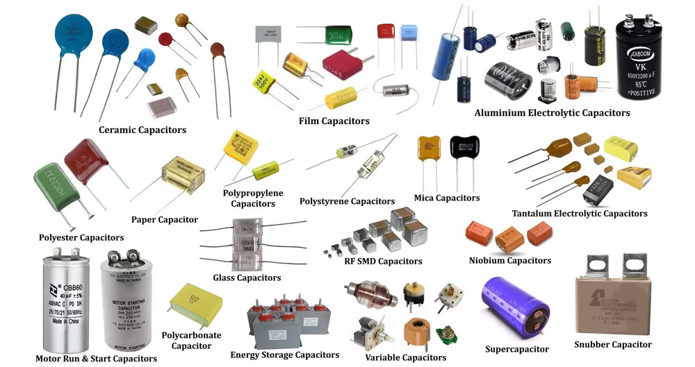
A capacitor is an electronic component that stores electrical energy for a short time and releases it when needed. It helps make the voltage smooth and stable in a circuit. Capacitors are used to reduce noise, filter signals, and support proper circuit operation. They are commonly used in power supplies, microcontrollers, and electronic devices. The unit of capacitance is Farad (F). Capacitors are important components in PCB design and electronic circuits.
5.Diode
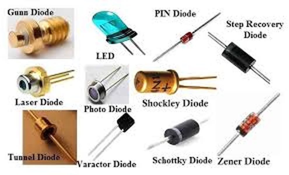
A diode is an electronic component that allows electric current to flow in only one direction and blocks it in the opposite direction. It helps protect circuits and control the direction of current flow. Diodes are commonly used in power supplies, LEDs, and electronic circuits. A common example is an LED, which is a light-emitting diode that produces light when current flows through it. Diodes are important for protecting components and ensuring proper circuit operation.
6.Transistors
A transistor is an electronic component used to control or amplify electric current in a circuit. It works like a switch or amplifier, allowing a small current to control a larger current. Transistors are used in microcontrollers, amplifiers, and many electronic devices. They are very important components in modern electronics and are used to build circuits like logic gates, signal amplifiers, and switching circuits.
7.Mosfet
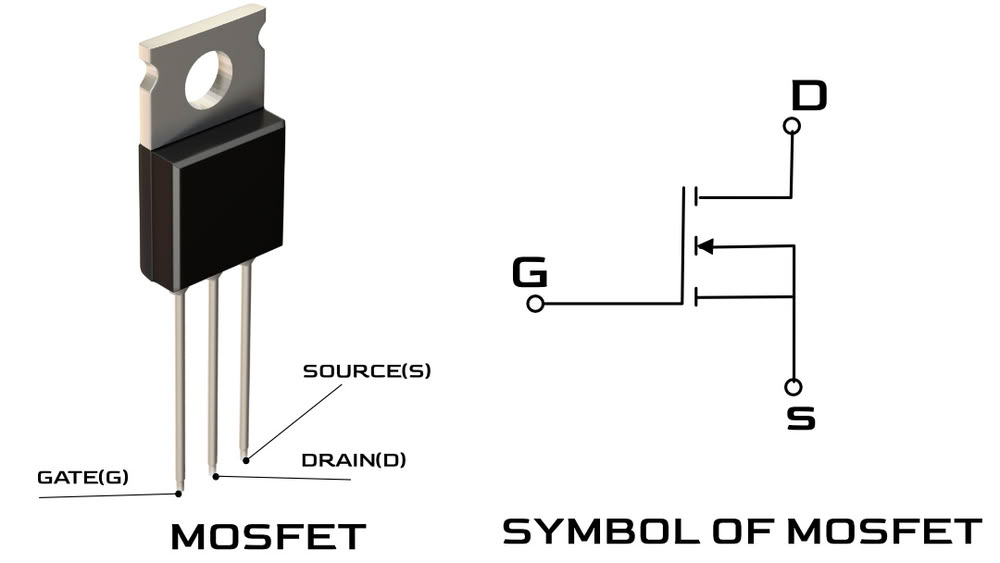
A MOSFET (Metal-Oxide-Semiconductor Field-Effect Transistor) is an electronic component used to switch or control the flow of electric current using voltage. It works like an electronic switch that can turn devices ON or OFF. MOSFETs are commonly used in microcontroller circuits, motor control, power supplies, and LED control. They are very efficient and can handle high current safely. MOSFETs are important in modern electronics.
8.Sensors
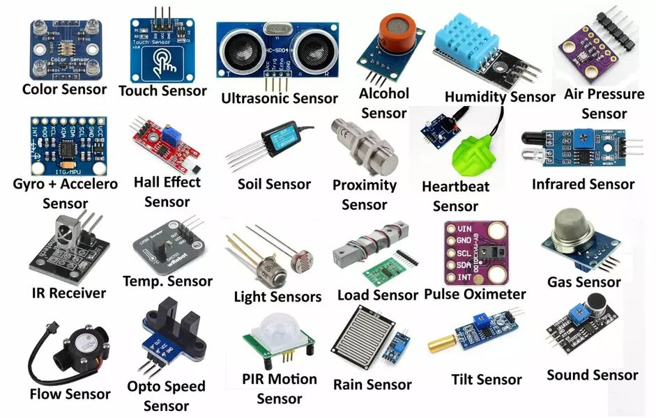
Sensors are electronic components that detect changes in the environment and convert them into electrical signals. They can detect things like temperature, light, motion, pressure, or distance. Sensors send this information to a microcontroller, which uses it to make decisions or control devices. Sensors are used in many electronic systems like automatic lights, robots, and smart devices. They help electronic circuits interact with the real world.
9.Actuators
Actuators are electronic or mechanical components that convert electrical signals into physical action. They make something move or work based on instructions from a microcontroller or circuit. For example, actuators can move motors, turn on lights, open doors, or create sound. Common actuators include motors, buzzers, and relays. They are important because they help electronic systems interact with and control the physical world.
Electronic Components Types:
Based on mounting typeSMD(Surface Mount Device)
SMD components are small electronic parts that are placed and soldered directly on the surface of the PCB.
Through Hole
Through-hole components are electronic parts with long legs that go through holes in the PCB and are soldered on the other side.

Active Components
Active components are electronic components that need external power to work and can control or amplify electric signals in a circuit. They are used to perform important functions like switching, amplifying, and processing signals. Examples of active components include transistors, microcontrollers, and integrated circuits. They are important because they help control and operate electronic systems.
Passive Components
Passive components are electronic components that do not need external power to work and cannot amplify signals. They only store, control, or resist electrical energy in a circuit. Examples of passive components include resistors, capacitors, and inductors. They help support and protect the circuit by controlling current and voltage.
Images took from following websites
Group assignment
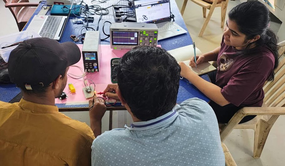
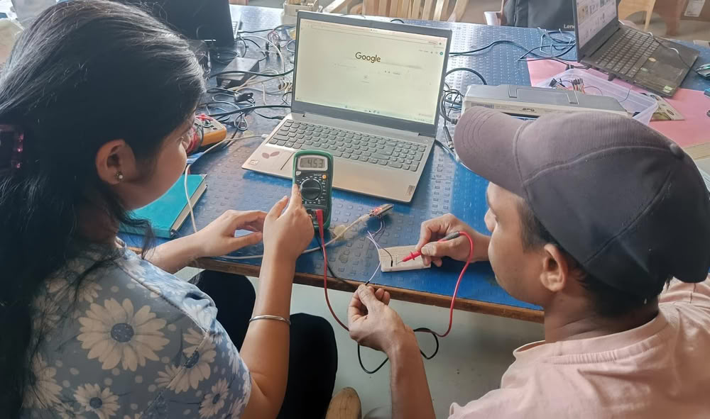
We used lab equipments to observe operations of an embedded microcontroller.
Multimeter
 |
|
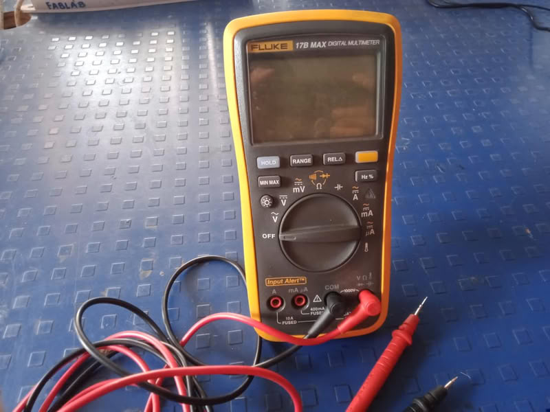
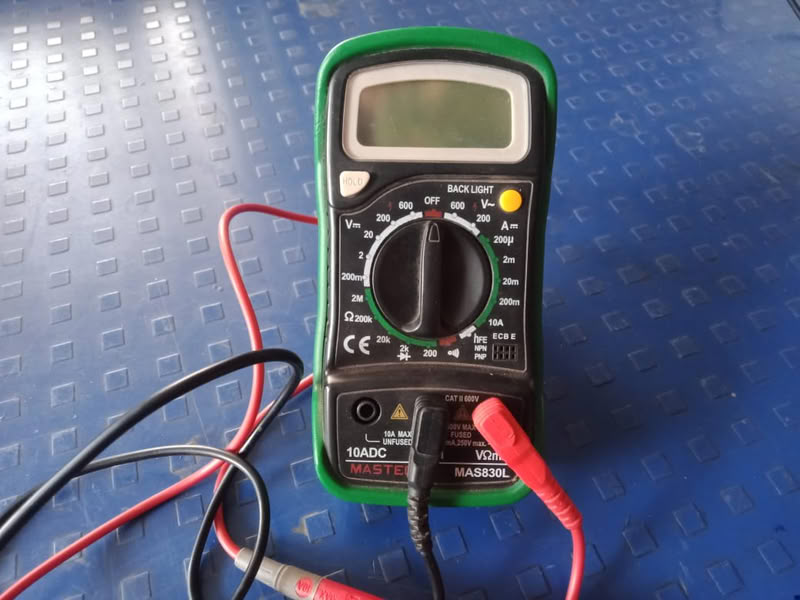
A multimeter is an electronic measuring instrument used to measure basic electrical parameters such as voltage, current, and resistance. It is an essential tool in electronics and electrical work for testing circuits, checking continuity, and troubleshooting faults. A multimeter can be either analog (with a needle display) or digital (with an LCD display), but digital multimeters are more commonly used because they provide accurate and easy-to-read measurements.
In practical use, a multimeter helps verify whether a component like a resistor, LED, or battery is working properly. It can measure DC voltage in batteries and power supplies, AC voltage in mains circuits, resistance of components, and continuity to check if a wire is connected. By selecting the correct mode and range, users can safely test circuits and ensure proper functioning of electronic systems.
Variable power supply
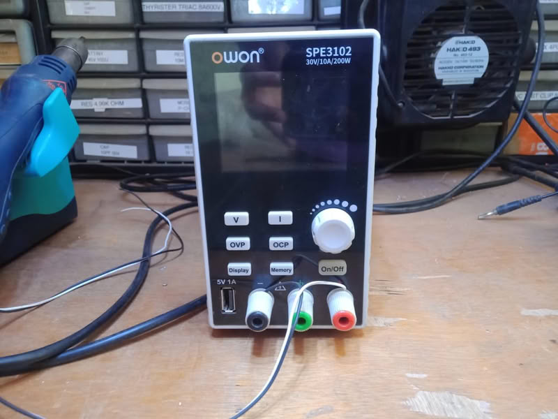
The OWON power supply is used to power microcontrollers, LEDs, sensors, and complete PCBs during testing and troubleshooting. By setting a proper voltage and current limit before connecting the circuit, it ensures safe operation and protects components from excessive current. It is especially useful in labs for prototyping, debugging circuits, and verifying power requirements of electronic projects.
Oscilloscope
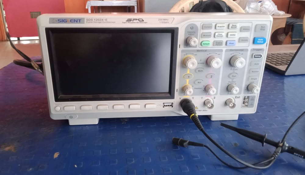
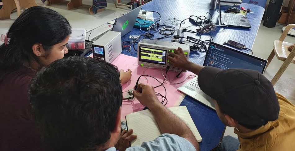
A Siglent oscilloscope is used to test and debug electronic circuits by observing signals from microcontrollers, sensors, communication lines, and power supplies. It helps measure signal frequency, voltage levels, rise and fall time, and detect noise or distortion in the circuit.
Testing of Voltage, Current and noticing waveform on oscilloscope
In this assignment, we tested the current and voltage of our circuit using a multimeter and also observed the signal using a Siglent oscilloscope manufactured by Siglent Technologies. We checked the waveform to understand how the signal changes over time and verified whether the circuit was working properly. Our instructor, Kishor Gaikwad, guided us throughout the process, explaining how to connect the probes correctly and how to set the proper measurement ranges. This practical session helped us clearly understand current, voltage, and waveform analysis.
 |
 |
 |
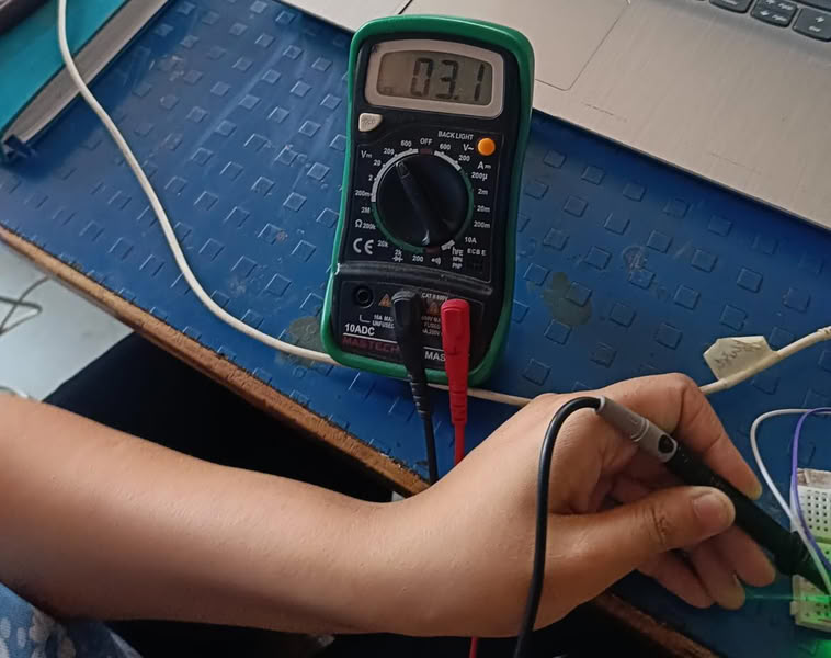
Current, Voltage checking using esp32
 |
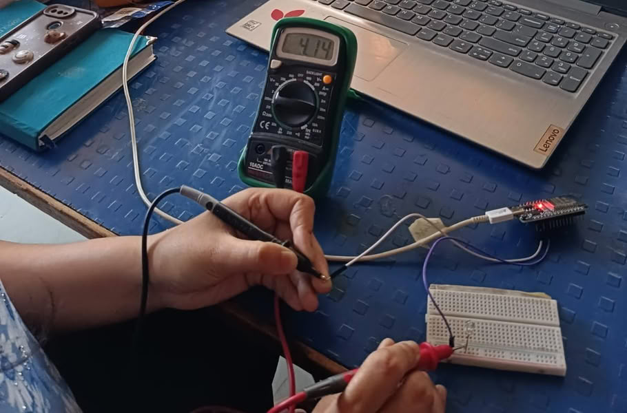 |
| We measured voltage of an LED . | We also measured current. |
 |
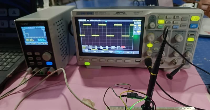 |
| Waveforms are generated using oscilloscope. |
Simulating a circuit
means testing and analyzing an electronic circuit virtually using software before building it physically.
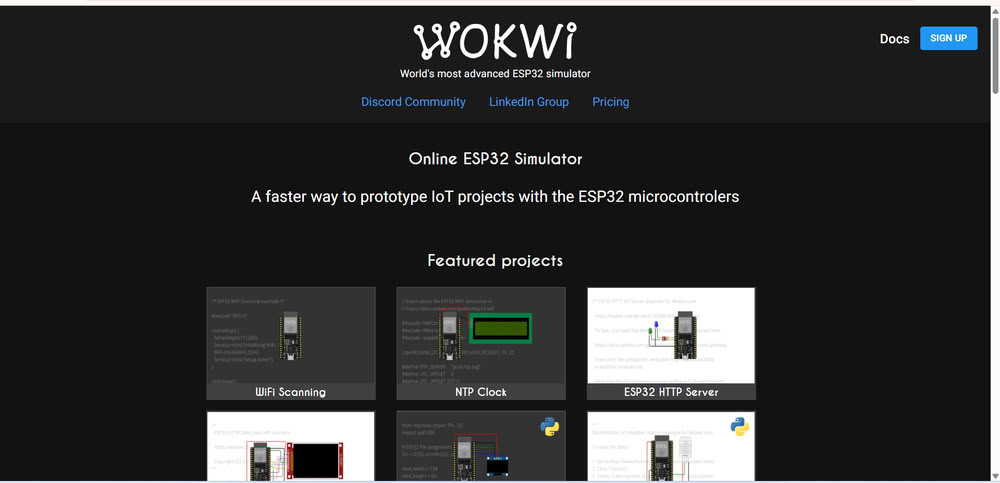
I used Wokwi for simulating a circuit.
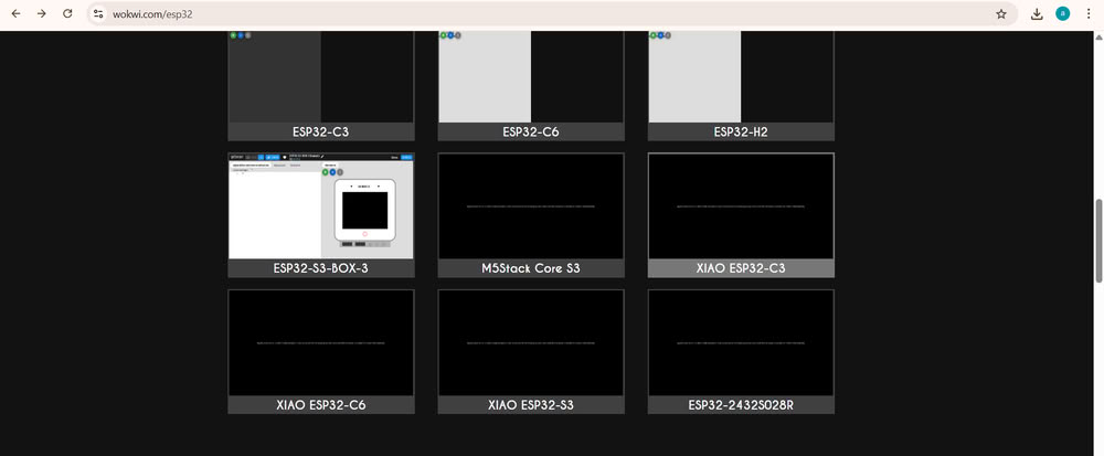
I choose xiao esp32c3.
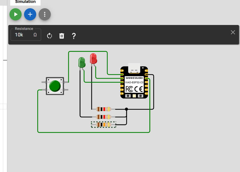
I add the components such as LED'S ,Resistors, Push button and connect them with microcontroller.
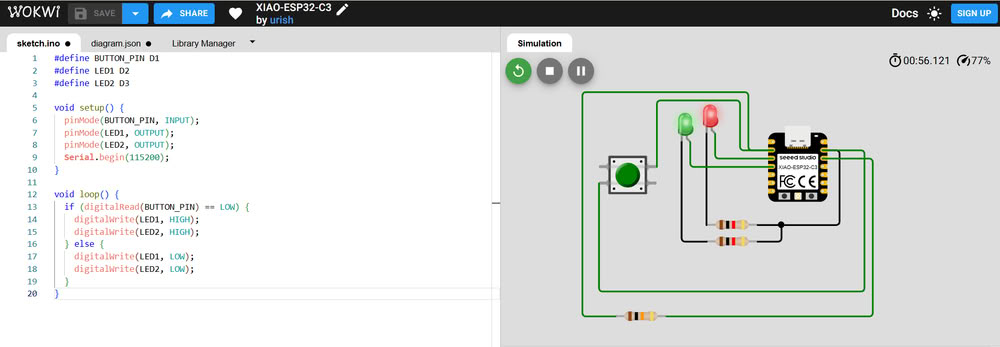
Then I add code and click on simulation button and when I press the button Both LED'S started blinking.
PCB designing tools
There are various tools to design a PCB KiCad, EasyEDA, Eagle but I choose KiCad.
KiCad
Why I choose KiCad?
KiCad is the best software for PCB making because it is free and open-source, which means I can use all its features without any cost. It provides all the necessary tools like schematic design, PCB layout, and 3D view in one place. This makes my work easier because I can design my complete PCB from circuit diagram to final layout using a single software.
I also chose KiCad because it is very useful for my Fab Academy assignments. It supports SMD components like 1206 resistors, LEDs, and tactile switches, which I am using in my design. KiCad also allows me to create custom footprints and generate Gerber files for PCB manufacturing. In my opinion, KiCad is beginner-friendly, powerful, and very helpful for learning and making professional PCB designs.
About KiCad:-
KiCad is a free and open-source software used for designing electronic circuits and printed circuit boards (PCBs). It helps users create schematics, design PCB layouts, and generate files needed for PCB manufacturing. KiCad provides different tools such as schematic editor, PCB editor, footprint editor, symbol editor, and 3D viewer. These tools allow users to design complete electronic boards from start to finish.
It supports both through-hole and SMD components like resistors, LEDs, microcontrollers, and sensors. KiCad also allows users to create custom symbols and footprints according to their project needs. It is very useful for learning electronics and making real PCB designs for projects like embedded systems and microcontroller boards.
Click to know about KiCad-Kicad
Step by step process to download kicad:-
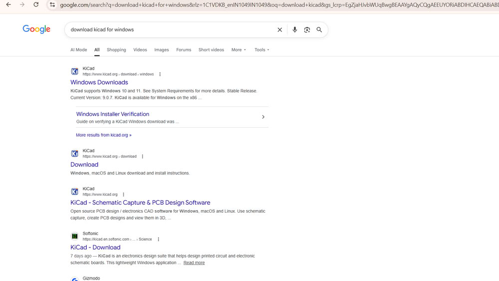
First, I searched for KiCad download for Windows on Google.

Then, I selected the proper release version

clicked Next to start the setup process.
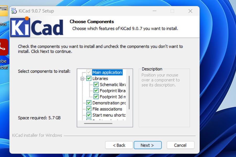
I completed the installation.

The Fab library is specific to the components needed for my project, so I searched for that library.

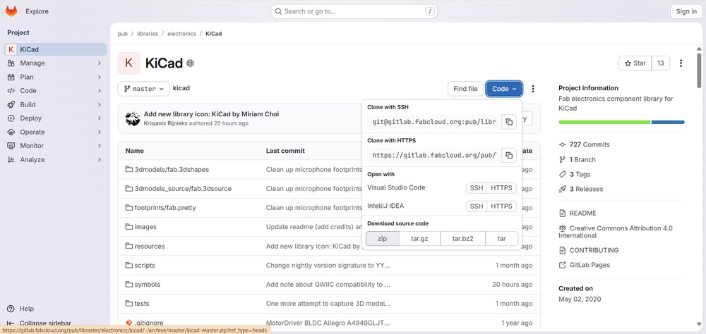
The Git interface opened, and I downloaded the Fab Library by clicking on the ZIP download option for my assignment.
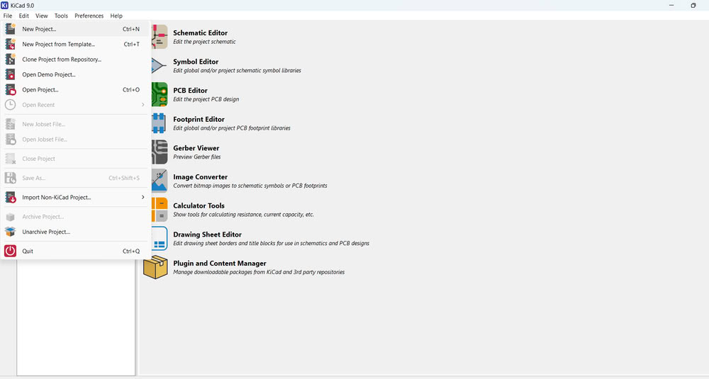
After that, I opened the KiCad software and clicked on New Project then saved the project in the proper folder.
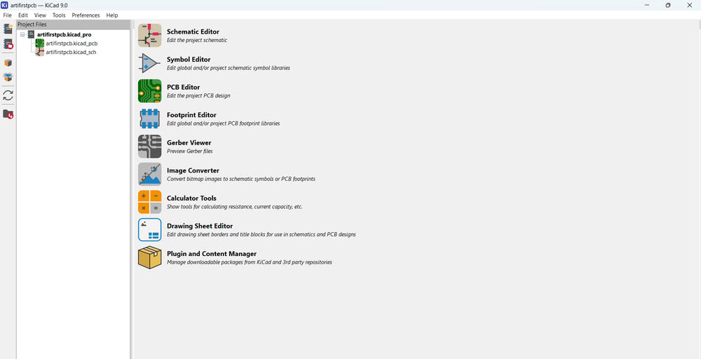
I could see my project folder created successfully.
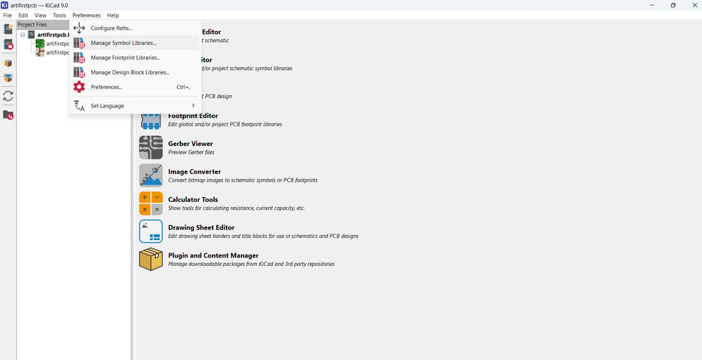
Then, under the Preferences option, I clicked on Manage Symbol Libraries.
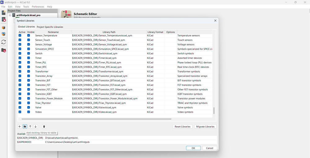
A dialog box appeared, where I clicked on the folder icon to select the Fab library that I had downloaded from Git.
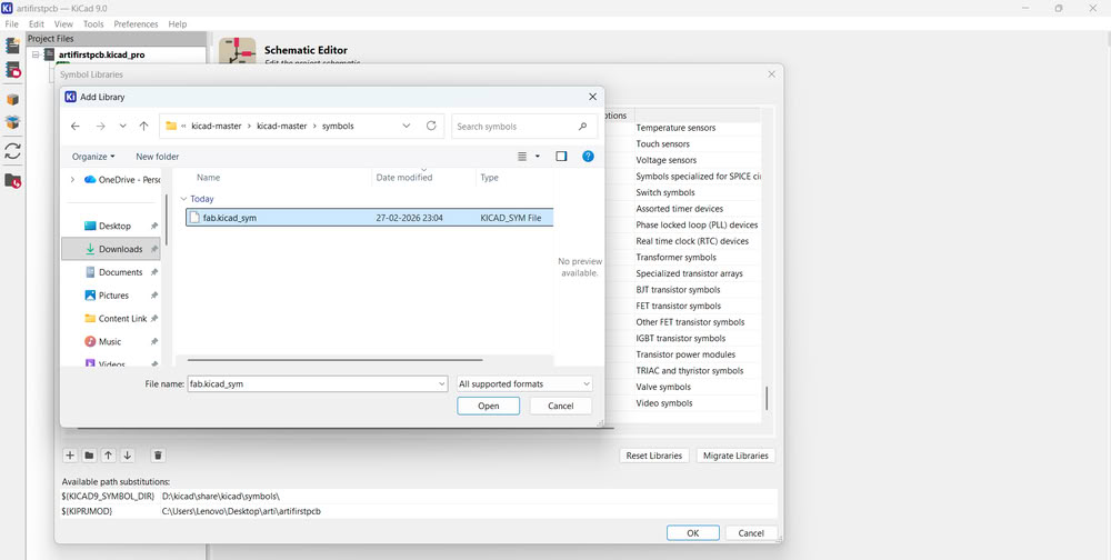
I selected the symbol file and opened it.
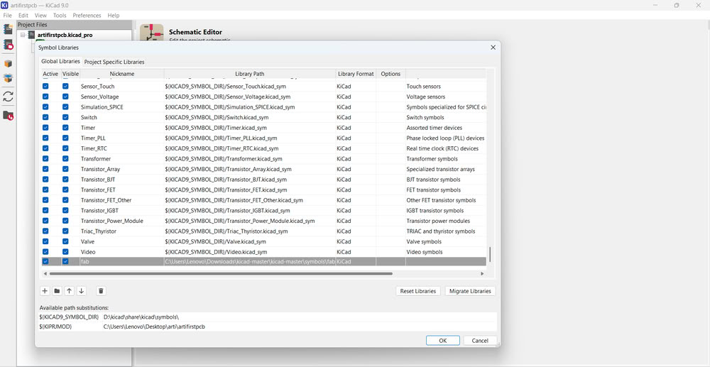
The symbol library was added successfully.
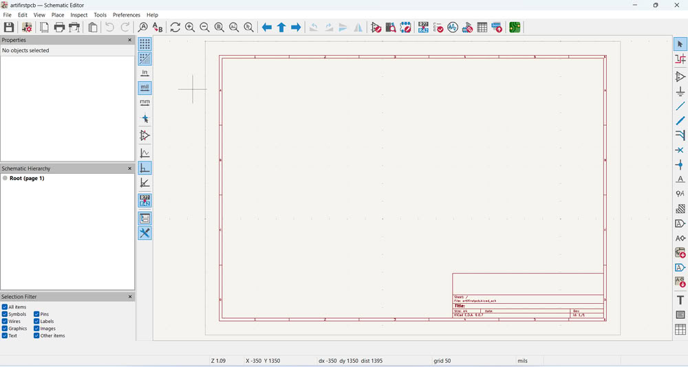
After adding the library, the PCB designing process began.I opened the Schematic Editor.
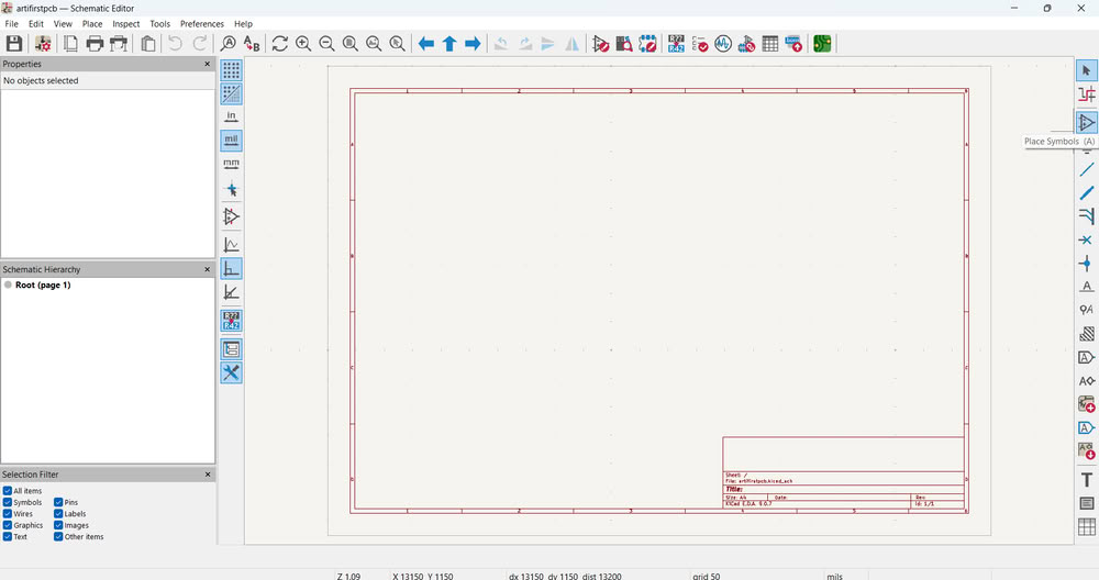
I clicked on Place Symbol to add components from the library.
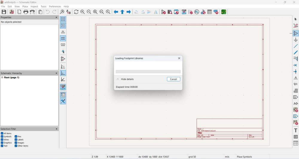
The required footprints started loading.
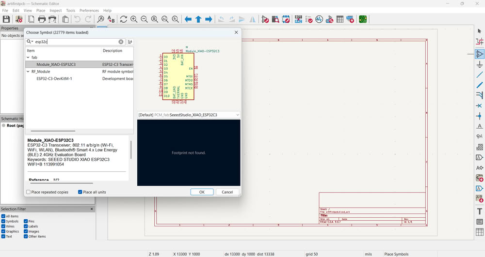
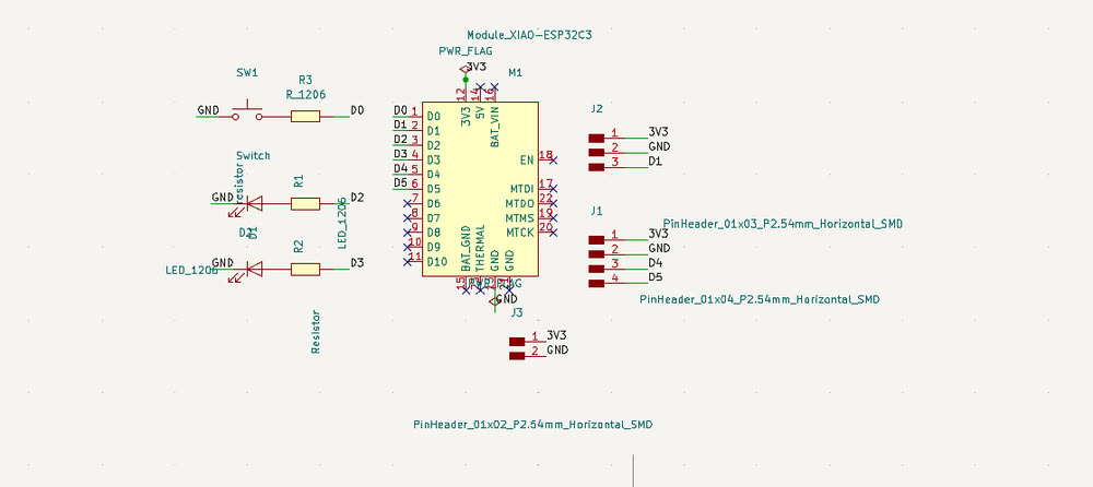
Then, I searched for the XIAO ESP32-C3.
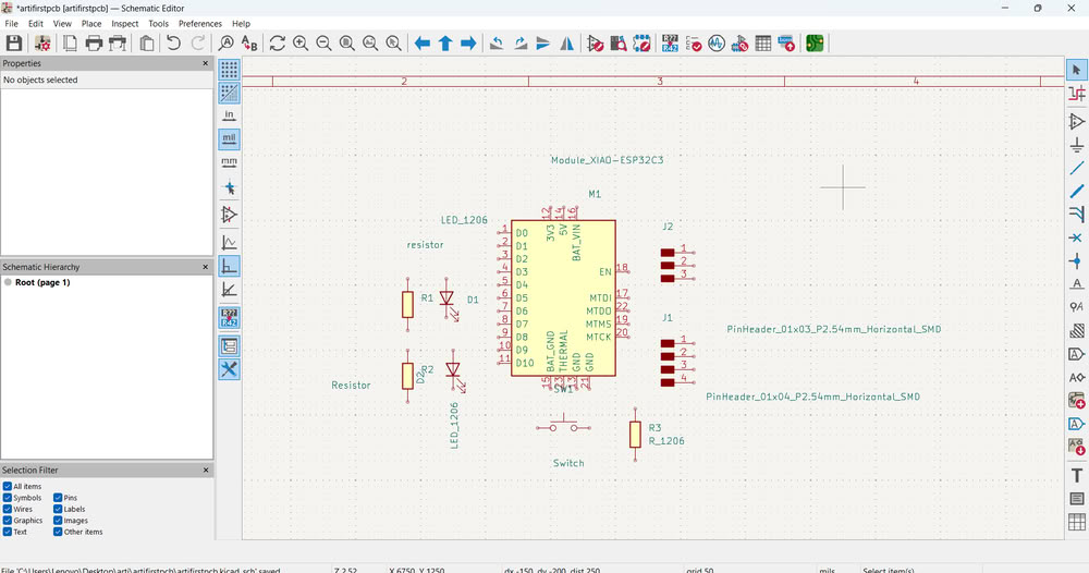
I added other components needed for my circuit, as shown in the image.
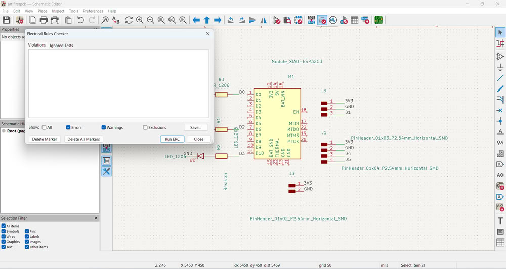
First, I ran ERC (Electrical Rule Check) in the schematic editor to verify that there were no electrical errors such as unconnected pins, short circuits, or missing power connections. This step is important because any mistake in the schematic will directly affect the PCB design. Ensuring the schematic is electrically correct avoids problems later during PCB manufacturing.
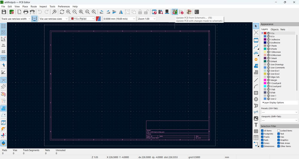
After confirming that ERC showed no critical errors, I opened the PCB Editor and clicked on Update PCB from Schematic. I selected this option to transfer all components and their connections (netlist) from the schematic to the PCB layout. This ensures that the PCB design exactly matches the schematic design and avoids manual mistakes.
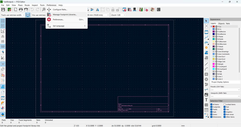
Before updating the PCB, I added the required footprint libraries. I did this because each schematic symbol must be linked to a physical footprint that represents the real component size and pad dimensions. Without correct footprints, the PCB cannot be manufactured properly. After adding the existing footprint libraries, I updated the PCB and confirmed that all footprints were successfully loaded onto the board.
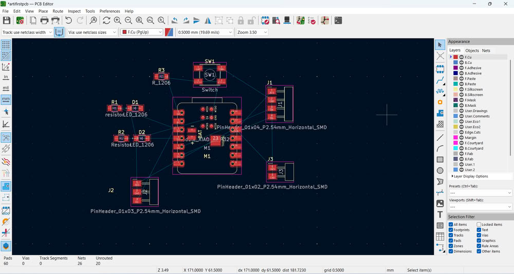
All the footprints were successfully loaded.
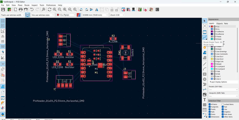
Next, I started the routing process. I connected every pin according to the yellow airwire lines shown in the PCB editor. Routing is necessary to create copper traces that electrically connect components based on the schematic. I ensured that all airwires disappeared, which confirms that all required connections were completed.
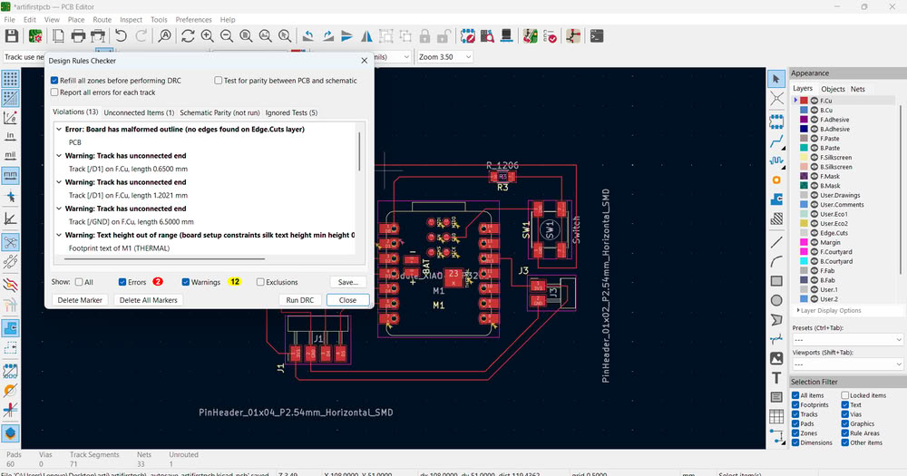
Then, I ran the DRC (Design Rule Check). I performed DRC to verify that the PCB follows all manufacturing constraints such as minimum trace width, clearance between tracks, and pad spacing. This step ensures that the board can be fabricated without errors.
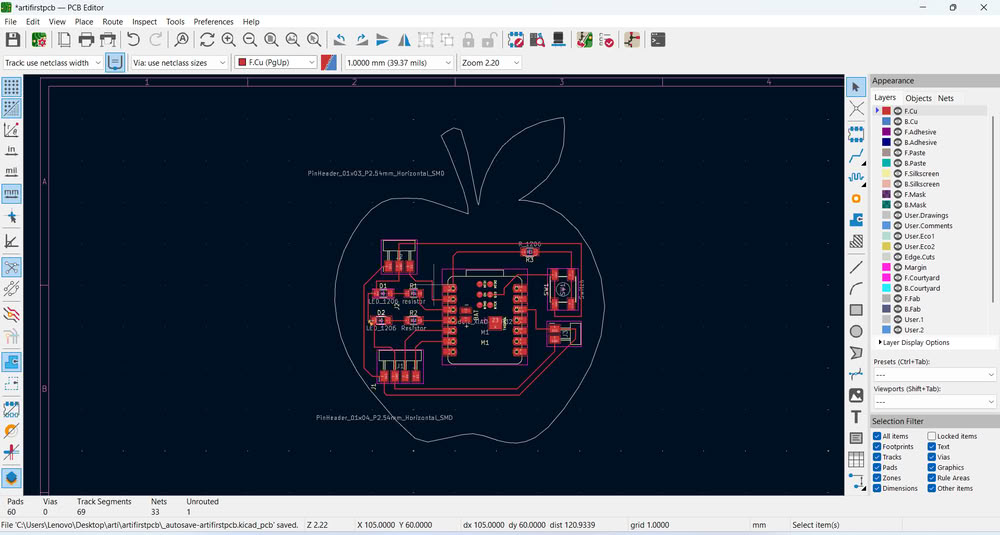
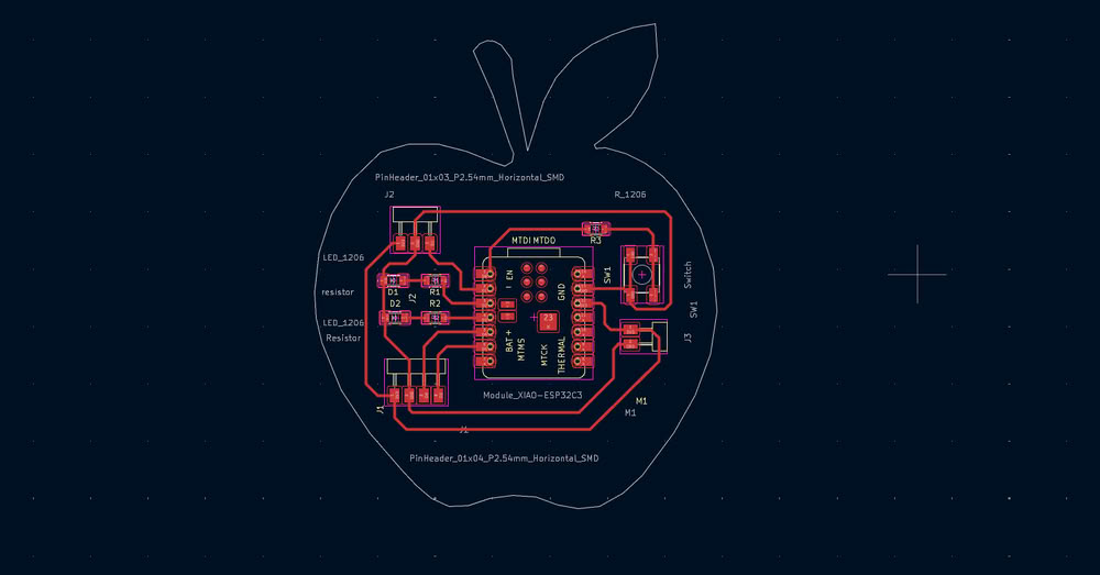
After running DRC lots of errors came, so first one is because no edgecut is given and track has unconnected end so I started solving errors one by one. I add apple shape edgecut by importing dxf file into pcb editor.I also connect tracks properly.
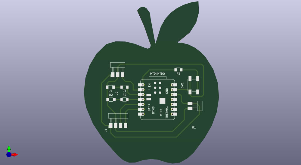
This is how my pcb looks beautiful in editor.
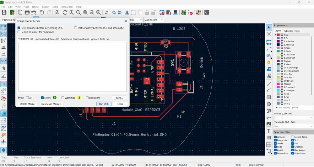
Then again I ran DRC to verify that the PCB follows all constraints without errors.
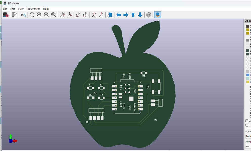
After confirming there were no major DRC errors, I opened the 3D Viewer to visually inspect the board. I used the 3D viewer to check component placement, board shape, and overall appearance. This helps identify mechanical issues or placement problems before fabrication.
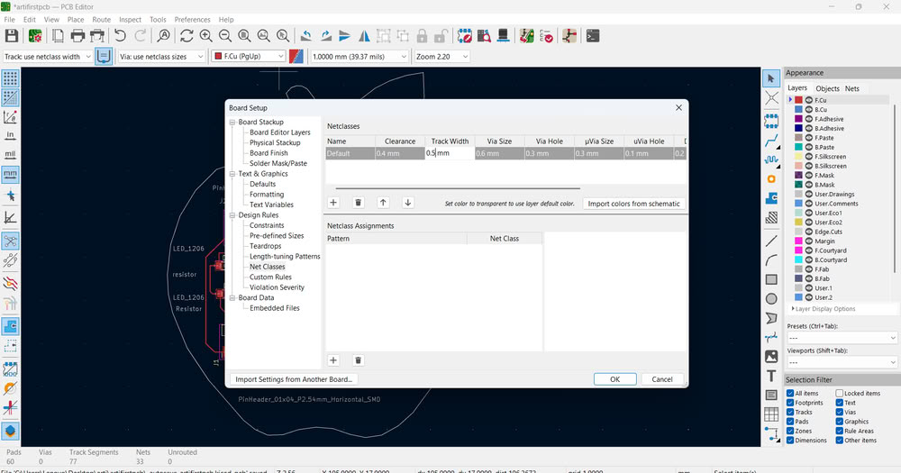
In this whole process I learned how to set default trace width and clearance in board setup.
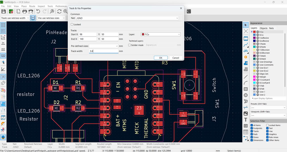
There is a rule for trace width based on current carrying capacity and manufacturing limits. I selected the routed traces and set the width to 0.5 mm. I chose 0.5 mm because it provides better current handling capability and improves mechanical strength compared to thinner traces like 0.25 mm or 0.3 mm. It also satisfies the design rule constraints of the PCB.
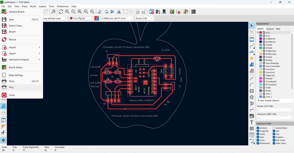
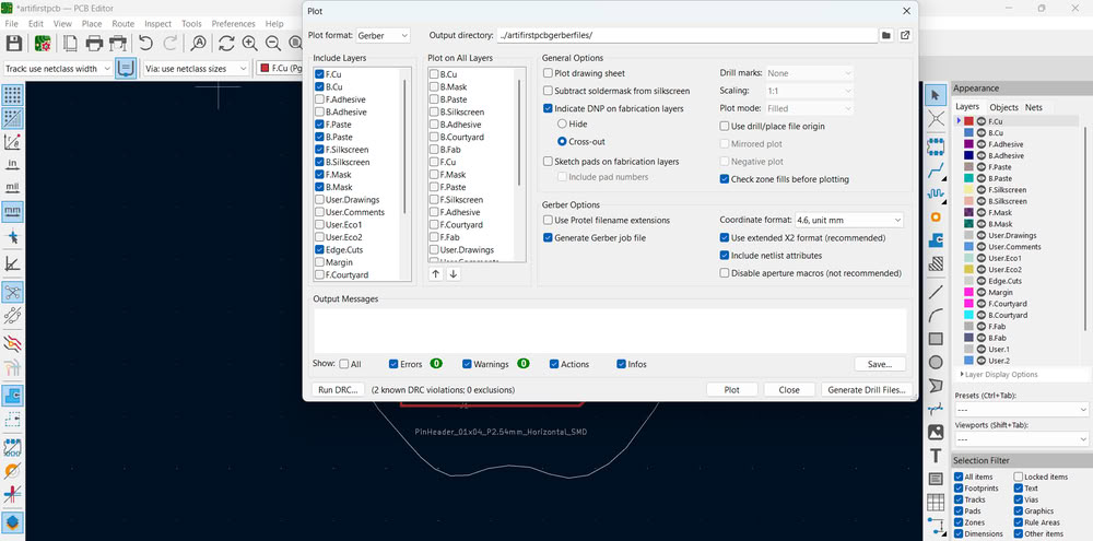
Finally, I clicked on the Plot option to generate manufacturing files. I selected Gerber format because Gerber files are the industry standard format used by PCB manufacturers. I selected the output directory and plotted the files. The Gerber files were successfully saved, which confirms the PCB data is ready for fabrication.
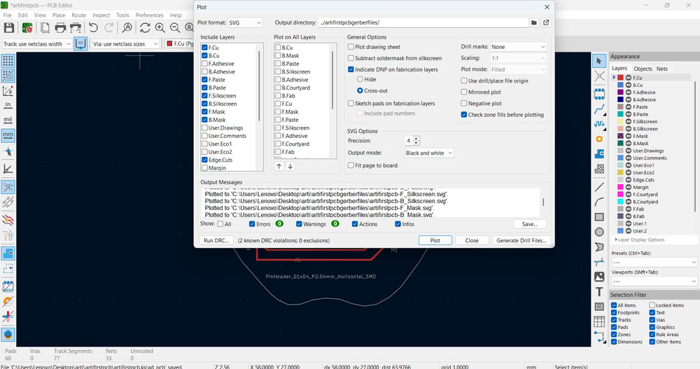
In a similar way, I also generated SVG format files.
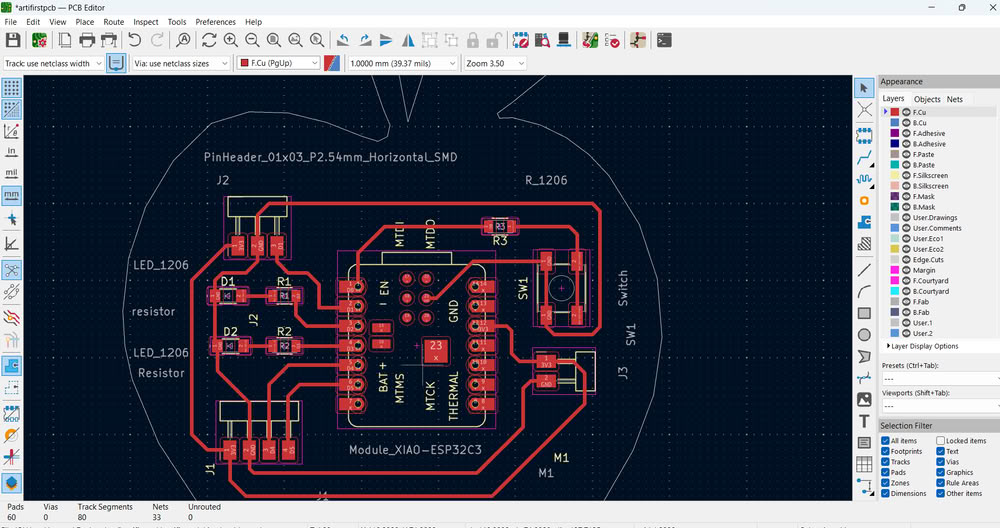
After generating the Gerber and SVG files, I carefully reviewed my PCB layout again and noticed that some of my routing tracks had 90-degree angles. Sharp 90-degree corners are not recommended in PCB design. So, usually 45 degree angle allow smoother current flow, improve reliability, and give the PCB a cleaner, more professional appearance. To correct this I remodified the routes.I again clicked on the Plot option and regenerated all the Gerber files for manufacturing and SVG files for PCB milling.
Here is my final schematic and editor image
I changed some pins in my PCB and update.
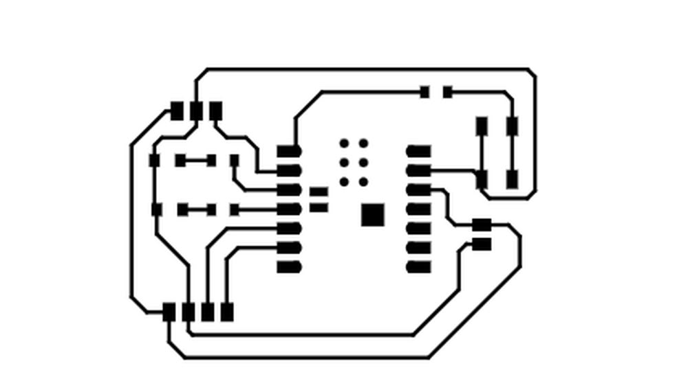
This is svg tracecut file.

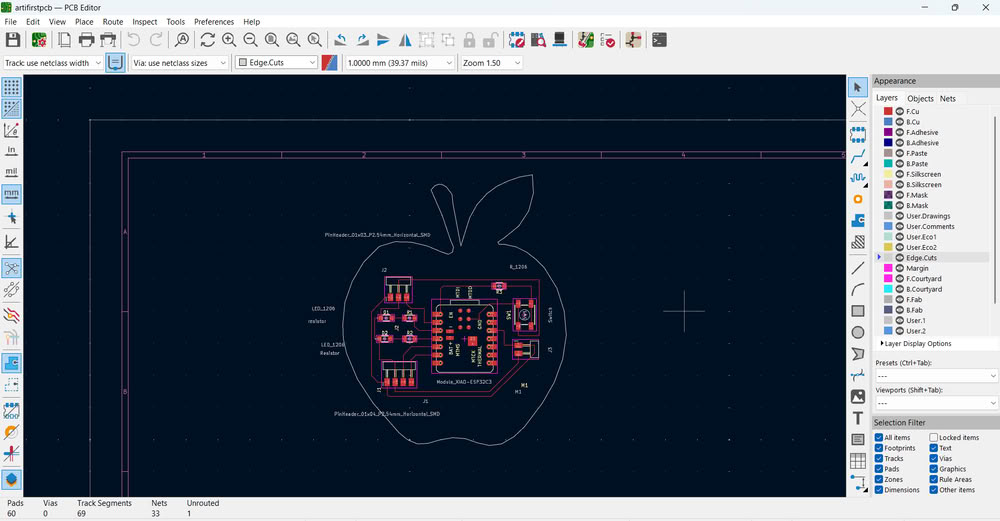
This is the edge cut file.